Configuring VXLANs

Overview

VXLAN Overview

The Cisco Nexus 3100 Series switches are designed for a hardware-based Virtual Extensible LAN (VXLAN) function. These switches can extend Layer 2 connectivity across the Layer 3 boundary and integrate between VXLAN and non-VXLAN infrastructures. Virtualized and multitenant data center designs can be shared over a common physical infrastructure.

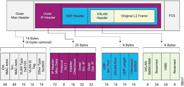
VXLANs enable you to extend Layer 2 networks across the Layer 3 infrastructure by using MAC-in-UDP encapsulation and tunneling. In addition, you can use a VXLAN to build a multitenant data center by decoupling tenant Layer 2 segments from the shared transport network.

When deployed as a VXLAN gateway, the Cisco Nexus 3100 Series switches can connect VXLAN and classic VLAN segments to create a common forwarding domain so that tenant devices can reside in both environments.

A VXLAN has the following benefits:

  • Flexible placement of multitenant segments throughout the data center.

    It extends Layer 2 segments over the underlying shared network infrastructure so that tenant workloads can be placed across physical pods in the data center.

  • Higher scalability to address more Layer 2 segments.

    A VXLAN uses a 24-bit segment ID called the VXLAN network identifier (VNID). The VNID allows a maximum of 16 million VXLAN segments to coexist in the same administrative domain. (In comparison, traditional VLANs use a 12-bit segment ID that can support a maximum of 4096 VLANs.)

  • Utilization of available network paths in the underlying infrastructure.

    VXLAN packets are transferred through the underlying network based on its Layer 3 header. It uses equal-cost multipath (ECMP) routing and link aggregation protocols to use all available paths.

 VXLAN Encapsulation and Packet Format

A VXLAN is a Layer 2 overlay scheme over a Layer 3 network. It uses MAC-in-UDP encapsulation to extend Layer 2 segments across the data center network. The transport protocol over the physical data center network is IP plus UDP. 

 A VXLAN defines a MAC-in-UDP encapsulation scheme where the original Layer 2 frame has a VXLAN header added and is then placed in a UDP-IP packet. With this MAC-in-UDP encapsulation, VXLAN tunnels Layer 2 network over the Layer 3 network. The VXLAN packet format is shown in the following figure. 

Figure 1. VXLAN Packet Format

A VXLAN uses an 8-byte VXLAN header that consists of a 24-bit VNID and a few reserved bits. The VXLAN header and the original Ethernet frame are in the UDP payload. The 24-bit VNID identifies the Layer 2 segments and maintains Layer 2 isolation between the segments. A VXLAN can support 16 million LAN segments. 

VXLAN Tunnel Endpoints

A VXLAN uses VXLAN tunnel endpoint (VTEP) devices to map tenants' end devices to VXLAN segments and to perform VXLAN encapsulation and deencapsulation. Each VTEP device has two types of interfaces:
  • Switch port interfaces on the local LAN segment to support local endpoint communication through bridging
  • IP interfaces to the transport network where the VXLAN encapsulated frames will be sent

A VTEP device is identified in the IP transport network by using a unique IP address, which is a loopback interface IP address. The VTEP device uses this IP address to encapsulate Ethernet frames and transmits the encapsulated packets to the transport network through the IP interface. A VTEP device learns the remote VTEP IP addresses and the remote MAC address-to-VTEP IP mapping for the VXLAN traffic that it receives.

The VXLAN segments are independent of the underlying network topology; conversely, the underlying IP network between VTEPs is independent of the VXLAN overlay. The IP network routes the encapsulated packets based on the outer IP address header, which has the initiating VTEP as the source IP address and the terminating VTEP or multicast group IP address as the destination IP address.

VXLAN Packet Forwarding Flow

A VXLAN uses stateless tunnels between VTEPs to transmit traffic of the overlay Layer 2 network through the Layer 3 transport network.

VXLAN Implementation on Cisco Nexus 3100 Platform Switches

The Cisco Nexus 3100 platform switches support the hardware-based VXLAN function that extends Layer 2 connectivity across the Layer 3 transport network and provides a high-performance gateway between VXLAN and non-VXLAN infrastructures.

Layer 2 Mechanisms for Broadcast, Unknown Unicast, and Multicast Traffic

A VXLAN on the Cisco Nexus 3100 platform switches uses flooding and dynamic MAC address learning to do the following:

  • Transport broadcast, unknown unicast, and multicast traffic

  • Discover remote VTEPs

  • Learn remote host MAC addresses and MAC-to-VTEP mappings for each VXLAN segment

A VXLAN can forward these traffic types as follows:

  • Using multicast in the core—IP multicast reduces the flooding of the set of hosts that are participating in the VXLAN segment. Each VXLAN segment, or VNID, is mapped to an IP multicast group in the transport IP network. The Layer 2 gateway uses Protocol Independent Multicast (PIM) to send and receive traffic from the rendezvous point (RP) for the IP multicast group. The multicast distribution tree for this group is built through the transport network based on the locations of participating VTEPs.

  • Using ingress replication—Each VXLAN segment or VXLAN network identifier (VNI) is mapped to a remote unicast peer. The Layer 2 frame is VXLAN encapsulated with the destination IP address as the remote unicast peer IP address and is sent out to the IP transport network where it gets unicast routed or forwarded to the remote destination.

Layer 2 Mechanisms for Unicast-Learned Traffic

The Cisco Nexus 3100 platform switches perform MAC address lookup-based forwarding for VXLAN unicast-learned traffic.

When Layer 2 traffic is received on the access side, a MAC address lookup is performed for the destination MAC address in the frame. If the lookup is successful, VXLAN forwarding is done based on the information retrieved as a result of the lookup. The lookup result provides the IP address of the remote VTEP from which this MAC address is learned. This Layer 2 frame is then UDP/IP encapsulated with the destination IP address as the remote VTEP IP address and is forwarded out of the appropriate network interface. In the Layer 3 cloud, this IP packet is forwarded to the remote VTEP through the route to that IP address in the network.

For unicast-learned traffic, you must ensure the following:

  • The route to the remote peer is known through a routing protocol or through static routes in the network.

  • Adjacency is resolved.

VXLAN Layer 2 Gateway as a Transit Multicast Router

A VXLAN Layer 2 gateway must terminate VXLAN-multicast traffic that is headed to any of the groups to which VNIs are mapped. In a network, a VXLAN Layer 2 gateway can be a multicast transit router for the downstream multicast receivers that are interested in the group's traffic. A VXLAN Layer 2 gateway must do some additional processing to ensure that VXLAN multicast traffic that is received is both terminated and multicast routed. This traffic processing is done in two passes:
  1. The VXLAN multicast traffic is multicast routed to all network receivers interested in that group's traffic.

  2. The VXLAN multicast traffic is terminated, decapsulated, and forwarded to all VXLAN access side ports.

ECMP and LACP Load Sharing with VXLANs

Encapsulated VXLAN packets are forwarded between VTEPs based on the native forwarding decisions of the transport network. Most data center transport networks are designed and deployed with multiple redundant paths that take advantage of various multipath load-sharing technologies to distribute traffic loads on all available paths.

A typical VXLAN transport network is an IP-routing network that uses the standard IP equal cost multipath (ECMP) to balance the traffic load among multiple best paths. To avoid out-of-sequence packet forwarding, flow-based ECMP is commonly deployed. An ECMP flow is defined by the source and destination IP addresses and optionally, the source and destination TCP or UDP ports in the IP packet header.

All the VXLAN packet flows between a pair of VTEPs have the same outer source and destination IP addresses, and all VTEP devices must use one identical destination UDP port that can be either the Internet Allocated Numbers Authority (IANA)-allocated UDP port 4789 or a customer-configured port. The only variable element in the ECMP flow definition that can differentiate VXLAN flows from the transport network standpoint is the source UDP port. A similar situation for Link Aggregation Control Protocol (LACP) hashing occurs if the resolved egress interface that is based on the routing and ECMP decision is an LACP port channel. LACP uses the VXLAN outer-packet header for link load-share hashing, which results in the source UDP port being the only element that can uniquely identify a VXLAN flow.

In the Cisco Nexus 3100 platform switch implementation of VXLANs, a hash of the inner frame's header is used as the VXLAN source UDP port. As a result, a VXLAN flow can be unique. The IP address and UDP port combination is in its outer header while the packet traverses the underlay transport network.

Guidelines and Limitations for VXLANs

VXLAN has the following guidelines and limitations:

  • The configuration of the multicast groups and Ingress Replication (IR) is not supported at the same time. You can configure and deploy either multicast groups or IR to deploy VXLAN.

  • The system vlan nve-overlay command is not required for Cisco Nexus 3000 platform switches with certain types of BroadCom ASICs. Therefore, do not enable the system vlan nve-overlay command.

  • In VXLAN on vPC configuration, the packets from North VTEP are decapped on the primary vPC switch and they are sent to all ports in the VLAN/VN-segment and they are also forwarded on the multicast link to the secondary vPC switch. Therefore, the NVE VNI counters are observed to increment for both Tx and Rx on the primary vPC switch, whereas the NVE VNI counters increment only for Rx on the secondary vPC switch.

  • It is recommended that the summation of the number of the multicast groups and the OIFLs to be used in a scaled environment should not exclude 1024, which is the current range of the multicast VXLAN VP.

  • Adjacencies are configured in different regions on an overlay or underlay network for different types of L3 interfaces based on whether or not the VXLAN, VNI or VFI are enabled on the interface. MAC rewrite does not happen if packets sent from a VFI enabled VLAN and hit an adjacency in an underlay network. So routing between VXLAN enabled VLANs and non-VXLAN enabled VLANs or L3 interfaces may fail.

  • IGMP snooping is supported on VXLAN VLANs.

  • VXLAN routing is supported for only the Cisco Nexus 3100-V platform switches. For other switches, the default Layer 3 gateway for VXLAN VLANs must be provisioned on a different device.

  • Ensure that the network can accommodate an additional 50 bytes for the VXLAN header.

  • Only one Network Virtualization Edge (NVE) interface is supported on a switch.

  • Layer 3 VXLAN uplinks are not supported in a nondefault virtual and routing forwarding (VRF) instance.

  • Only one VXLAN IP adjacency is possible per physical interface.

  • SVIs over VXLAN VLAN for routing are supported for only the Cisco Nexus 3100-V platform switches.

  • Switched Port Analyzer (SPAN) Tx for VXLAN-encapsulated traffic is not supported for the Layer 3 uplink interface.

  • Access control lists (ACLs) and quality of service (QoS) for VXLAN traffic to access direction are not supported.

  • SNMP is not supported on the NVE interface.

  • Native VLANs for VXLAN are not supported.

  • For ingress replication configurations, multiple VNIs can now have the same remote peer IP configured.

  • The VXLAN source UDP port is determined based on the VNID and source and destination IP addresses.

  • The UDP port configuration must be done before the NVE interface is enabled. If the UDP configuration must be changed while the NVE interface is enabled, you must shut down the NVE interface, make the UDP configuration change, and then reenable the NVE interface.


    Note

    The VXLAN UDP port is not configurable on the Cisco Nexus 3100-V platform switches.


  • Inter-VNI routing and IGMP snooping for VXLAN-enabled VLANs are not supported on Cisco Nexus 3232C and 3264Q platform switches.

  • In a VXLAN EVPN setup that has 2K VNI scale configuration, the control plane downtime takes more than 200 seconds. You must configure the graceful restart time as 300 seconds to avoid BGP flap.

FHRP Over VXLAN

Overview of FHRP over VXLAN

Overview of FHRP

Starting with Release 7.0(3)I7(1), you can configure First Hop Redundancy Protocol (FHRP) over VXLAN on Cisco Nexus 3000 Series switches. The FHRP provides a redundant Layer 3 traffic path. It provides fast failure detection and transparent switching of the traffic flow. The FHRP avoids the use of the routing protocols on all the devices. It also avoids the traffic loss that is associated with the routing or the discovery protocol convergence. It provides an election mechanism to determine the next best gateway. Current FHRP supports HSRPv1, HSRPv2, VRRPv2, and VRRPv3.

FHRP over VXLAN

The FHRP serves at the Layer 3 VXLAN redundant gateway for the hosts in the VXLAN. The Layer 3 VXLAN gateway provides routing between the VXLAN segments and routing between the VXLAN to the VLAN segments. Layer 3 VXLAN gateway also serves as a gateway for the external connectivity of the hosts.

Guidelines and Limitations for FHRP Over VXLAN

See the following guidelines and limitations for configuring FHRP over VXLAN:

  • When using FHRP with VXLAN, ARP-ETHER TCAM must be carved using the arp-ether 256 double-wide CLI command.

  • Configuring FHRP over VXLAN is supported for both IR and multicast flooding of the FHRP packets. The FHRP protocol working does not change for configuring FHRP over VXLAN.

  • The FHRP over VXLAN feature is supported for flood and learn only.

  • For Layer 3 VTEPs in BGP EVPN, only anycast GW is supported.

FHRP Over VXLAN Topology

In the following topology, the FHRP is configured on the Spine Layer. The FHRP protocols synchronize its state with the hellos that get flooded on the overlay without having a dedicated Layer 2 link in between the peers. The FHRP operates in an active/standby state as no vPC is being deployed.


Note

Bi-Directional Forwarding (BFD) is not supported with HSRP in the new topology.


The following image illustrates the new topology that supports a FHRP over VXLAN configuration:

Figure 2. Configuring FHRP Over VXLAN

Following is the configuration example of the new topology:

S1 FHRP configuration with HSRP
# VLAN with VNI
vlan 10
  vn-segment 10000

# Layer-3 Interface with FHRP (HSRP)
interface vlan 10
 ip address 192.168.1.2
  hsrp 10
  ip 192.168.1.1

S2 FHRP configuration with HSRP
# VLAN with VNI
vlan 10
  vn-segment 10000

# Layer-3 Interface with FHRP (HSRP)
interface vlan 10
 ip address 192.168.1.3
  hsrp 10
  ip 192.168.1.1

Note

The FHRP configuration can leverage HSRP or VRRP. No vPC peer-link is necessary and therefore no VLAN is allowed on the vPC peer-link. The VNI mapped to the VLAN must be configured on the NVE interface and it is associated with the used BUM replication mode (Multicast or Ingress Replication).


Considerations for VXLAN Deployment

The following are some of the considerations while deploying VXLANs:

  • A loopback interface IP is used to uniquely identify a VTEP device in the transport network.

  • To establish IP multicast routing in the core, an IP multicast configuration, PIM configuration, and Rendezvous Point (RP) configuration are required.

  • You can configure VTEP-to-VTEP unicast reachability through any IGP protocol.

  • You can configure a VXLAN UDP destination port as required. The default port is 4789.

  • The default gateway for VXLAN VLANs should be provisioned on a different upstream router.

  • VXLAN multicast traffic should always use the RPT shared tree.

  • An RP for the multicast group on the VTEP is a supported configuration. However, you must configure the RP for the multicast group at the spine layer/upstream device. Because all multicast traffic traverses the RP, it is more efficient to have this traffic directed to a spine layer/upstream device.

vPC Guidelines and Limitations for VXLAN Deployment

  • The VXLAN multicast encapsulation path has duplicate members of the VPC peer-link on the VPC peers. This design has been adopted to support anycast RP and the service orphan traffic. For all the access side traffic, now two copies of a packet are sent over the VPC peer-link on the multicast path, one native and one VXLAN header encapsulated.

  • You must bind NVE to a loopback address that is separate form other loopback addresses required by Layer 3 protocols. Use a dedicated loopback address for VXLAN.

  • Multicast traffic on a vPC that is hashed toward the non-DF switch traverses the multichassis EtherChannel trunk (MCT) and is encapsulated on the DF node.

  • In a VXLAN vPC, consistency checks are performed to ensure that NVE configurations and VN-Segment configurations are identical across vPC peers.

  • The router ID for unicast routing protocols must be different from the loopback IP address used for VTEP.

  • Configure an SVI between vPC peers and advertise routes between the vPC peers by using a routing protocol with higher routing metric. This action ensures that the IP connectivity of the vPC node does not go down if one vPC node fails.

Configuration Guidelines for VXLAN VPC Setup and Expected Behaviors in Various Scenarios

  • VPC peers must have identical configurations:
    • Consistent VLAN to VN-segment mapping.

    • Consistent NVE1 binding to the same loopback interface.

    • Using the same secondary IP address.

    • Using different primary IP addresses.

    • Consistent VNI to group mapping.

  • For multicast, the VPC node that receives the (S, G) join from the RP (rendezvous point) becomes the DF (Designated Forwarder). On the DF node, the encapsulation routes are installed for multicast.

  • The decap routes are installed based on the election of a decapper from between the VPC primary node and the VPC secondary node. The winner of the decap election is the node with the least cost to the RP.

  • However, if the cost to the RP is the same for both nodes, the VPC primary node is elected. The winner of the decap election has the decap mroute installed. The other node does not have a decap route installed.

  • On a VPC device, the BUM traffic (broadcast, unknown-unicast, and multicast traffic) from hosts is replicated on the the peer-link. A copy is made of every native packet and each native packet is sent across the peer-link to service the orphan-ports connected to the peer VPC switch.

  • To prevent traffic loops in VXLAN networks, native packets ingressing the peer-link cannot be sent to an uplink. However, if the peer switch is the encapper, the copied packet traverses the peer-link and it is sent to the uplink.

  • When the peer-link is shut, the loopback address on the VPC secondary is brought down and the status is Admin Shut. This is done so that the route to the loopback is withdrawn on the upstream and that the upstream can divert all the traffic to the VPC primary.

    Note

    Orphans that are connected to the secondary vPC experience a loss of traffic when the MCT is shut down. This situation is similar to Layer 2 orphans in a secondary vPC of a traditional vPC setup.


  • When the peer-link is no-shut, the NVE loopback address is brought up again and the route is advertised upstream attracting the traffic.

  • For VPC,
    • The loopback interface has 2 IP addresses: the primary IP address and the secondary IP address.

    • The primary IP address is unique and is used by Layer 3 protocols.

    • The secondary IP address on loopback is necessary because the interface NVE uses it for the VTEP IP address.

    • The secondary IP address must be same on both vPC peers.

    • The VPC peer-gateway feature must be enabled on both peers.

  • As a best practice, use peer-switch, peer gateway, ip arp sync, ipv6 nd sync configurations for improved convergence in VPC topologies.

  • When the NVE or loopback is shut in VPC configurations:
    • If the NVE or loopback is shut only on the primary VPC switch, the global VxLAN VPC consistency checker fails. Then the NVE, loopback, and VPCs are taken down on the secondary VPC switch.

    • If the NVE or loopback is shut only on the secondary VPC switch, the global VXLAN VPC consistency checker fails. Then the NVE, loopback, and secondary VPC are brought down on the secondary. The traffic continues to flow through the primary VPC switch.

  • As a best practice, you should keep both the NVE and loopback up on both the primary and secondary VPC switches.

  • Redundant anycast RPs configured in the network for multicast load-balancing and RP redundancy are supported on VPC VTEP topologies.

  • Enabling vpc peer-switch configuration is mandatory. For peer-switch functionality, at least one SVI is required to be enabled across the peer-link and also configured with PIM. This provides a backup path in the case when VTEP loses complete connectivity to the spine. Remote peer reachability is re-routed over the peer-link in this case.

Configuring VXLAN Traffic Forwarding

There are two options for forwarding broadcast, unknown unicast and multicast traffic on a VXLAN Layer 2 gateway. Layer 2 Mechanisms for Broadcast, Unknown Unicast, and Multicast Traffic provides more information about these two options.

Before you enable and configure VXLANs, ensure that the following configurations are complete:
  • For IP multicast in the core, ensure that the IP multicast configuration, the PIM configuration, and the RP configuration are complete, and that a routing protocol exists.

  • For ingress replication, ensure that a routing protocol exists for reaching unicast addresses.

    Note

    On a Cisco Nexus 3100 Series switch that functions as a VXLAN Layer 2 gateway, note that traffic that is received on the access side cannot trigger an ARP on the network side. ARP for network side interfaces should be resolved either by using a routing protocol such as BGP, or by using static ARP. This requirement is applicable for ingress replication cases alone, not for multicast replication cases.


Enabling and Configuring the PIM Feature

Before you can access the PIM commands, you must enable the PIM feature.

This is a prerequisite only for multicast replication.

Before you begin

Ensure that you have installed the LAN Base Services license.

Procedure

  Command or Action Purpose
Step 1

switch# configure terminal

Enters global configuration mode.

Step 2

switch(config)# feature pim

Enables PIM. By default, PIM is disabled.

Step 3

(Optional) switch(config)# show running-config pim

(Optional)

Shows the running-configuration information for PIM, including the feature command.

Step 4

(Optional) switch(config)# copy running-config startup-config

(Optional)

Saves the change persistently through reboots and restarts by copying the running configuration to the startup configuration.

Example

This example shows how to enable the PIM feature:

switch# configure terminal
switch(config)# feature pim
switch(config)# ip pim spt-threshold infinity group-list rp_name
switch(config)# show running-config pim

!Command: show running-config pim
!Time: Wed Mar 26 08:04:23 2014

version 6.0(2)U3(1)
feature pim

ip pim spt-threshold infinity group-list rp_name

Configuring a Rendezvous Point

You can configure a rendezvous point (RP) by configuring the RP address on every router that will participate in the PIM domain.

This is a prerequisite only for multicast replication.

Before you begin

Ensure that you have installed the LAN Base Services license and enabled PIM.

Procedure

  Command or Action Purpose
Step 1

switch# configure terminal

Enters global configuration mode.

Step 2

switch(config)# ip pim rp-address rp-address [group-list ip-prefix | route-map policy-name]

Configures a PIM RP address for a multicast group range. You can specify a route-map policy name that lists the group prefixes to use with the match ip multicast command. The default mode is ASM. The default group range is 224.0.0.0 through 239.255.255.255.

Step 3

(Optional) switch(config)# show ip pim group-range [ip-prefix] [vrf {vrf-name | all | default | management}]

(Optional)

Displays PIM modes and group ranges.

Step 4

(Optional) switch(config)# copy running-config startup-config

(Optional)

Saves the change persistently through reboots and restarts by copying the running configuration to the startup configuration.

Example

This example shows how to configure an RP:

switch# configure terminal
switch(config)# ip pim rp-address 111.1.1.1 group-list 224.0.0.0/4

Enabling a VXLAN

Enabling VXLANs involves the following:

  • Enabling the VXLAN feature

  • Enabling VLAN to VN-Segment mapping

Before you begin

Ensure that you have installed the VXLAN Enterprise license.

Procedure

  Command or Action Purpose
Step 1

switch# configure terminal

Enters global configuration mode.

Step 2

switch(config)# [no] feature nv overlay

Enables the VXLAN feature.

Step 3

switch (config)# [no] feature vn-segment-vlan-based

Configures the global mode for all VXLAN bridge domains.

Enables VLAN to VN-Segment mapping. VLAN to VN-Segment mapping is always one-to-one.

Step 4

(Optional) switch(config)# copy running-config startup-config

(Optional)

Saves the change persistently through reboots and restarts by copying the running configuration to the startup configuration.

Example

This example shows how to enable a VXLAN and configure VLAN to VN-Segment mapping:

switch# configure terminal
switch(config)# feature nv overlay
switch(config)# feature vn-segment-vlan-based
switch(config)# copy running-config startup-config

Mapping a VLAN to a VXLAN VNI

Procedure

  Command or Action Purpose
Step 1

switch# configure terminal

Enters global configuration mode.

Step 2

switch(config)# vlan vlan-id

Specifies a VLAN.

Step 3

switch(config-vlan)# vn-segment vnid

Specifies the VXLAN virtual network identifier (VNID). The range of values for vnid is 1 to 16777214.

Example

This example shows how to map a VLAN to a VXLAN VNI:

switch# configure terminal
switch(config)# vlan 3100
switch(config-vlan)# vn-segment 5000

Configuring a Routing Protocol for NVE Unicast Addresses

Configuring a routing protocol for unicast addresses involves the following:

  • Configuring a dedicated loopback interface for NVE reachability.

  • Configuring the routing protocol network type.

  • Specifying the routing protocol instance and area for an interface.

  • Enabling PIM sparse mode in case of multicast replication.


Note

Open shortest path first (OSPF) is used as the routing protocol in the examples.


This is a prerequisite for both multicast and ingress replication.

Guidelines for configuring a routing protocol for unicast addresses are as follows:
  • For ingress replication, you can use a routing protocol that can resolve adjacency, such as BGP.
  • When using unicast routing protocols in a vPC topology, explicitly configure a unique router ID for the vPC peers to avoid the VTEP loopback IP address (which is the same on the vPC peers) being used as the router ID.

Procedure

  Command or Action Purpose
Step 1

switch# configure terminal

Enters global configuration mode.

Step 2

switch(config)# interface loopback instance

Creates a dedicated loopback interface for the NVE interface. The instance range is from 0 to 1023.

Step 3

switch(config-if)# ip address ip-address/length

Configures an IP address for this interface.

Step 4

switch(config-if)# ip ospf network {broadcast | point-to-point}

Configures the OSPF network type to a type other than the default for an interface.

Step 5

switch(config-if)# ip router ospf instance-tag area area-id

Specifies the OSPF instance and area for an interface.

Step 6

switch(config-if)# ip pim sparse-mode

Enables PIM sparse mode on this interface. The default is disabled.

Enable the PIM sparse mode in case of multicast replication.

Example

This example shows how to configure a routing protocol for NVE unicast addresses:

switch# configure terminal
switch(config)# interface loopback 10
switch(config-if)# ip address 222.2.2.1/32
switch(config-if)# ip ospf network point-to-point
switch(config-if)# ip router ospf 1 area 0.0.0.0
switch(config-if)# ip pim sparse-mode

Creating a VXLAN Destination UDP Port

The UDP port configuration should be done before the NVE interface is enabled.


Note

If the configuration must be changed while the NVE interface is enabled, ensure that you shut down the NVE interface, make the UDP configuration change, and then reenable the NVE interface.


Ensure that the UDP port configuration is done network-wide before the NVE interface is enabled on the network.

The VXLAN UDP source port is determined based on the VNID and source and destination IP addresses.

Procedure

  Command or Action Purpose
Step 1

switch# configure terminal

Enters global configuration mode.

Step 2

switch(config)# vxlan udp port number

Specifies the destination UDP port number for VXLAN encapsulated packets. The default destination UDP port number is 4789.

Example

This example shows how to create a VXLAN destination UDP port:

switch# configure terminal
switch(config)# vxlan udp port 4789

Creating and Configuring an NVE Interface

An NVE interface is the overlay interface that initiates and terminates VXLAN tunnels. You can create and configure an NVE (overlay) interface.

Procedure

  Command or Action Purpose
Step 1

switch# configure terminal

Enters global configuration mode.

Step 2

switch(config)# interface nve instance

Creates a VXLAN overlay interface that initiates and terminates VXLAN tunnels.

Note 
Only one NVE interface is allowed on the switch.
Step 3

switch(config-if-nve)# source-interface loopback instance

Specifies a source interface.

The source interface must be a loopback interface that is configured on the switch with a valid /32 IP address. This /32 IP address must be known by the transit routers in the transport network and the remote VTEPs.

Example

This example shows how to create and configure an NVE interface:

switch# configure terminal
switch(config)# interface nve 1
switch(config-if-nve)# source-interface loopback 10

Configuring Replication for a VNI

Replication for VXLAN network identifier (VNI) can be configured in one of two ways:
  • Multicast replication
  • Ingress replication

Configuring Multicast Replication

Before you begin
  • Ensure that the NVE interface is created and configured.

  • Ensure that the source interface is specified.

Procedure
Command or Action Purpose

switch(config-if-nve)# member vni {vnid mcast-group multicast-group-addr | vnid- range mcast-group start-addr [end-addr]}

Maps VXLAN VNIs to the NVE interface and assigns a multicast group to the VNIs.

Example

This example shows how to map a VNI to an NVE interface and assign it to a multicast group:

switch(config-if-nve)# member vni 5000 mcast-group 225.1.1.1

Configuring Ingress Replication

Before you begin
  • Ensure that the NVE interface is created and configured.

  • Ensure that the source interface is specified.

Procedure
  Command or Action Purpose
Step 1

switch(config-if-nve)# member vni vnid

Maps VXLAN VNIs to the NVE interface.

Step 2

switch(config-if-nve-vni)# ingress-replication protocol static

Enables static ingress replication for the VNI.

Step 3

switch(config-if-nve-vni)# peer-ip ip-address

Enables the peer IP.

Note 
  • A VNI can be associated only with a single IP address.

  • An IP address can be associated only with a single VNI.

Example

This example shows how to map a VNI to an NVE interface and create a unicast tunnel:

switch(config-if-nve)# member vni 5001
switch(config-if-nve-vni)# ingress-replication protocol static
switch(config-if-nve-vni)# peer-ip 111.1.1.1

Configuring Q-in-VNI

Using Q-in-VNI provides a way for you to segregate traffic by mapping to a specific port. In a multi-tenant environment, you can specify a port to a tenant and send/receive packets over the VXLAN overlay.

Notes about configuring Q-in-VNI:

  • Q-in-VNI is supported only for the Cisco Nexus 3100-V and 3132C-Z platform switches.

  • The dot1q mode is not supported for 40G ports.

  • Q-in-Q to Q-in-VNI interworking is supported.

  • Q-in-VNI only supports VXLAN bridging. It does not support VXLAN routing.

  • Q-in-VNI does not support FEX.

  • When configuring access ports and trunk ports:

    • You can have access ports, trunk ports and dot1q ports on different interfaces on the same switch.

    • You cannot have the same VLAN configured for both dot1q and trunk ports/access ports.

Before you begin

Configuring the Q-in-VNI feature requires:

  • The base port mode must be a dot1q tunnel port with an access VLAN configured.

  • VNI mapping is required for the access VLAN on the port.

Procedure

  Command or Action Purpose
Step 1

configure terminal

Enters global configuration mode.

Step 2

interface type port

Enters interface configuration mode.

Step 3

switchport mode dot1q-tunnel

Creates a 802.1Q tunnel on the port.

Step 4

switchport access vlan vlan-id

Specifies the port assigned to a VLAN.

Step 5

spanning-tree bpdufilter enable

Enables BPDU Filtering for the specified spanning tree edge interface. By default, BPDU Filtering is disabled.

Example

The following example shows how to configure Q-in-VNI:


switch# config terminal
switch(config)# interface ethernet 1/4
switch(config-if)# switchport mode dot1q-tunnel
switch(config-if)# switchport access vlan 10
switch(config-if)# spanning-tree bpdufilter enable
switch(config-if)# 

Verifying the VXLAN Configuration

Use one of the following commands to verify the VXLAN configuration, to display the MAC addresses, and to clear the MAC addresses:

Command Purpose
show nve interface nve id

Displays the configuration of an NVE interface.

show nve vni

Displays the VNI that is mapped to an NVE interface.

show nve peers

Displays peers of the NVE interface.

show interface nve id counters

Displays all the counters for an NVE interface.

show nve vxlan-params

Displays the VXLAN UDP port configured.

show mac address-table

Displays both VLAN and VXLAN MAC addresses.

clear mac address-table dynamic

Clears all MAC address entries in the MAC address table.

Example

This example shows how to display the configuration of an NVE interface:

switch# show nve interface nve 1
Interface: nve1, State: up, encapsulation: VXLAN
Source-interface: loopback10 (primary: 111.1.1.1, secondary: 0.0.0.0)


This example shows how to display the VNI that is mapped to an NVE interface for multicast replication:

switch# show nve vni
Interface          VNI        Multicast-group   VNI State
----------------   --------   ---------------   ---------
nve1               5000       225.1.1.1          Up


This example shows how to display the VNI that is mapped to an NVE interface for ingress replication:

switch# show nve vni
Interface          VNI        Multicast-group   VNI State
----------------   --------   ---------------   ---------
nve1               5000       0.0.0.0           Up


This example shows how to display the peers of an NVE interface:

switch# show nve peers
Interface          Peer-IP           Peer-State
----------------   ---------------   -------------
nve1               111.1.1.1          Up

This example shows how to display the counters of an NVE interface:

switch# show interface nv 1 counter

--------------------------------------------------------------------------------
Port                                  InOctets                    InUcastPkts
--------------------------------------------------------------------------------
nve1                                         0                              0

--------------------------------------------------------------------------------
Port                               InMcastPkts                    InBcastPkts
--------------------------------------------------------------------------------
nve1                                         0                              0

--------------------------------------------------------------------------------
Port                                 OutOctets                   OutUcastPkts
--------------------------------------------------------------------------------
nve1                                         0                              0

--------------------------------------------------------------------------------
Port                              OutMcastPkts                   OutBcastPkts
--------------------------------------------------------------------------------
nve1                                         0                              0

This example shows how to display the VXLAN UDP port configured:

switch# show nve vxlan-params
VxLAN Dest. UDP Port: 4789

This example shows how to display both VLAN and VXLAN MAC addresses:

switch# show mac address-table 
Legend:
        * - primary entry, G - Gateway MAC, (R) - Routed MAC, O - Overlay MAC
        age - seconds since first seen,+ - primary entry using vPC Peer-Link
   VLAN     MAC Address      Type      age     Secure NTFY   Ports/SWID.SSID.LID
---------+-----------------+--------+---------+------+----+------------------
* 109      0000.0410.0902    dynamic   470        F    F  Po2233
* 109      0000.0410.0912    dynamic   470        F    F  Po2233
* 109      0000.0410.0912    dynamic   470        F    F  nve1(1.1.1.200)
* 108      0000.0410.0802    dynamic   470        F    F  Po2233
* 108      0000.0410.0812    dynamic   470        F    F  Po2233
* 107      0000.0410.0702    dynamic   470        F    F  Po2233
* 107      0000.0410.0712    dynamic   470        F    F  Po2233
* 107      0000.0410.0712    dynamic   470        F    F  nve1(1.1.1.200)
* 106      0000.0410.0602    dynamic   470        F    F  Po2233
* 106      0000.0410.0612    dynamic   470        F    F  Po2233
* 105      0000.0410.0502    dynamic   470        F    F  Po2233
* 105      0000.0410.0512    dynamic   470        F    F  Po2233
* 105      0000.0410.0512    dynamic   470        F    F  nve1(1.1.1.200)
* 104      0000.0410.0402    dynamic   470        F    F  Po2233
* 104      0000.0410.0412    dynamic   470        F    F  Po2233

This example shows how to clear all MAC address entries in the MAC address table:

switch# clear mac address-table dynamic 
switch#