- Creating a Port Channel
- Adding a Port to a Port Channel
- Configuring Load Balancing Using Port Channels
- Configuring Hardware Hashing for Multicast Traffic
- Enabling LACP
- Configuring the Channel Mode for a Port
- Configuring LACP Port Channel MinLinks
- Configuring the LACP Fast Timer Rate
- Configuring the LACP System Priority and System ID
- Configuring the LACP Port Priority
Configuring Port Channels
This chapter contains the following sections:
- Information About Port Channels
- Configuring Port Channels
- Verifying Port Channel Configuration
- Verifying the Load-Balancing Outgoing Port ID
- Feature History for Port Channels
Information About Port Channels
A port channel bundles up to 16 individual interfaces into a group to provide increased bandwidth and redundancy. Port channeling also load balances traffic across these physical interfaces. The port channel stays operational as long as at least one physical interface within the port channel is operational.
You create an port channel by bundling compatible interfaces. You can configure and run either static port channels or port channels running the Link Aggregation Control Protocol (LACP).
Any configuration changes that you apply to the port channel are applied to each member interface of that port channel. For example, if you configure Spanning Tree Protocol (STP) parameters on the port channel, Cisco NX-OS applies those parameters to each interface in the port channel.
You can use static port channels, with no associated protocol, for a simplified configuration. For more efficient use of the port channel, you can use the Link Aggregation Control Protocol (LACP), which is defined in IEEE 802.3ad. When you use LACP, the link passes protocol packets.
- Understanding Port Channels
- Compatibility Requirements
- Load Balancing Using Port Channels
- Understanding LACP
Understanding Port Channels
Using port channels, Cisco NX-OS provides wider bandwidth, redundancy, and load balancing across the channels.
You can collect up to 16 ports into a static port channel or you can enable the Link Aggregation Control Protocol (LACP). Configuring port channels with LACP requires slightly different steps than configuring static port channels.
 Note |
Cisco NX-OS does not support Port Aggregation Protocol (PAgP) for port channels. |
A port channel bundles individual links into a channel group to create a single logical link that provides the aggregate bandwidth of up to 16 physical links. If a member port within a port channel fails, traffic previously carried over the failed link switches to the remaining member ports within the port channel.
Each port can be in only one port channel. All the ports in an port channel must be compatible; they must use the same speed and operate in full-duplex mode. When you are running static port channels, without LACP, the individual links are all in the on channel mode; you cannot change this mode without enabling LACP.
Note |
You cannot change the mode from ON to Active or from ON to Passive. |
You can create a port channel directly by creating the port-channel interface, or you can create a channel group that acts to aggregate individual ports into a bundle. When you associate an interface with a channel group, Cisco NX-OS creates a matching port channel automatically if the port channel does not already exist. You can also create the port channel first. In this instance, Cisco NX-OS creates an empty channel group with the same channel number as the port channel and takes the default configuration.
Note |
A port channel is operationally up when at least one of the member ports is up and that port’s status is channeling. The port channel is operationally down when all member ports are operationally down. |
Compatibility Requirements
When you add an interface to a port channel group, Cisco NX-OS checks certain interface attributes to ensure that the interface is compatible with the channel group. Cisco NX-OS also checks a number of operational attributes for an interface before allowing that interface to participate in the port-channel aggregation.
The compatibility check includes the following operational attributes:
- Port mode
- Access VLAN
- Trunk native VLAN
- Allowed VLAN list
- Speed
- 802.3x flow control setting
- MTU
- Broadcast/Unicast/Multicast Storm Control setting
- Priority-Flow-Control
- Untagged CoS
Use the show port-channel compatibility-parameters command to see the full list of compatibility checks that Cisco NX-OS uses.
You can only add interfaces configured with the channel mode set to on to static port channels. You can also only add interfaces configured with the channel mode as active or passive to port channels that are running LACP. You can configure these attributes on an individual member port.
When the interface joins a port channel, the following individual parameters are replaced with the values on the port channel:
The following interface parameters remain unaffected when the interface joins a port channel:
After you enable forcing a port to be added to a channel group by entering the channel-group force command, the following two conditions occur:
-
When an interface joins a port channel the following parameters are removed and they are operationally replaced with the values on the port channel; however, this change will not be reflected in the running-configuration for the interface: -
When an interface joins or leaves a port channel, the following parameters remain unaffected:
Load Balancing Using Port Channels
Cisco NX-OS load balances traffic across all operational interfaces in a port channel by reducing part of the binary pattern formed from the addresses in the frame to a numerical value that selects one of the links in the channel. Port channels provide load balancing by default and the basic configuration uses the following criteria to select the link:
- For a Layer 2 frame, it uses the source and destination MAC addresses.
- For a Layer 3 frame, it uses the source and destination MAC addresses and the source and destination IP addresses.
-
For a Layer 4 frame, it uses the source and destination MAC addresses and the source and destination IP addresses.
Note
You have the option to include the source and destination port number for the Layer 4 frame.
You can configure the switch to use one of the following methods to load balance across the port channel:
- Destination MAC address
- Source MAC address
- Source and destination MAC address
- Destination IP address
- Source IP address
- Source and destination IP address
- Destination TCP/UDP port number
- Source TCP/UDP port number
- Source and destination TCP/UDP port number
| Configuration |
Layer 2 Criteria |
Layer 3 Criteria |
Layer 4 Criteria |
|---|---|---|---|
| Destination MAC |
Destination MAC |
Destination MAC |
Destination MAC |
| Source MAC |
Source MAC |
Source MAC |
Source MAC |
| Source and destination MAC |
Source and destination MAC |
Source and destination MAC |
Source and destination MAC |
| Destination IP |
Destination MAC |
Destination MAC, destination IP |
Destination MAC, destination IP |
| Source IP |
Source MAC |
Source MAC, source IP |
Source MAC, source IP |
| Source and destination IP |
Source and destination MAC |
Source and destination MAC, source and destination IP |
Source and destination MAC, source and destination IP |
| Destination TCP/UDP port |
Destination MAC |
Destination MAC, destination IP |
Destination MAC, destination IP, destination port |
| Source TCP/UDP port |
Source MAC |
Source MAC, source IP |
Source MAC, source IP, source port |
| Source and destination TCP/UDP port |
Source and destination MAC |
Source and destination MAC, source and destination IP |
Source and destination MAC, source and destination IP, source and destination port |
Use the option that provides the balance criteria with the greatest variety in your configuration. For example, if the traffic on a port channel is going only to a single MAC address and you use the destination MAC address as the basis of port-channel load balancing, the port channel always chooses the same link in that port channel; using source addresses or IP addresses might result in better load balancing.
Understanding LACP
LACP Overview
Note |
You must enable the LACP feature before you can configure and use LACP functions. |
The following figure shows how individual links can be combined into LACP port channels and channel groups as well as function as individual links.
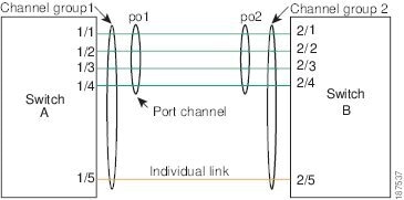
With LACP, just like with static port-channels, you can bundle up to 16 interfaces in a channel group.
Note |
When you delete the port channel, Cisco NX-OS automatically deletes the associated channel group. All member interfaces revert to their previous configuration. |
You cannot disable LACP while any LACP configurations are present.
LACP ID Parameters
LACP uses the following parameters:
- LACP system priority—Each system that runs LACP has an LACP system priority value. You can accept the default value of 32768 for this parameter, or you can configure a value between 1 and 65535. LACP uses the system priority with the MAC address to form the system ID and also uses the system priority during negotiation with other devices. A higher system priority value means a lower priority.
Note |
The LACP system ID is the combination of the LACP system priority value and the MAC address. |
- LACP port priority—Each port configured to use LACP has an LACP port priority. You can accept the default value of 32768 for the LACP port priority, or you can configure a value between 1 and 65535. LACP uses the port priority with the port number to form the port identifier. LACP uses the port priority to decide which ports should be put in standby mode when there is a limitation that prevents all compatible ports from aggregating and which ports should be put into active mode. A higher port priority value means a lower priority for LACP. You can configure the port priority so that specified ports have a lower priority for LACP and are most likely to be chosen as active links, rather than hot-standby links.
- LACP administrative key—LACP automatically configures an administrative key value equal to the channel-group number on each port configured to use LACP. The administrative key defines the ability of a port to aggregate with other ports. A port’s ability to aggregate with other ports is determined by these factors:
Channel Modes
Individual interfaces in port channels are configured with channel modes. When you run static port channels, with no protocol, the channel mode is always set to on. After you enable LACP globally on the device, you enable LACP for each channel by setting the channel mode for each interface to active or passive. You can configure either channel mode for individual links in the LACP channel group.
Note |
You must enable LACP globally before you can configure an interface in either the active or passive channel mode. |
The following table describes the channel modes.
| Channel Mode |
Description |
|---|---|
| passive |
LACP mode that places a port into a passive negotiating state, in which the port responds to LACP packets that it receives but does not initiate LACP negotiation. |
| active |
LACP mode that places a port into an active negotiating state, in which the port initiates negotiations with other ports by sending LACP packets. |
| on |
All static port channels, that is, that are not running LACP, remain in this mode. If you attempt to change the channel mode to active or passive before enabling LACP, the device returns an error message. You enable LACP on each channel by configuring the interface in that channel for the channel mode as either active or passive. When an LACP attempts to negotiate with an interface in the on state, it does not receive any LACP packets and becomes an individual link with that interface; it does not join the LACP channel group. |
Both the passive and active modes allow LACP to negotiate between ports to determine if they can form a port channel, based on criteria such as the port speed and the trunking state. The passive mode is useful when you do not know whether the remote system, or partner, supports LACP.
Ports can form an LACP port channel when they are in different LACP modes as long as the modes are compatible as in the following examples:
- A port in active mode can form a port channel successfully with another port that is in active mode.
- A port in active mode can form a port channel with another port in passive mode.
- A port in passive mode cannot form a port channel with another port that is also in passive mode because neither port will initiate negotiation.
- A port in on mode is not running LACP.
LACP Marker Responders
Using port channels, data traffic may be dynamically redistributed due to either a link failure or load balancing. LACP uses the Marker Protocol to ensure that frames are not duplicated or reordered because of this redistribution. Cisco NX-OS supports only Marker Responders.
LACP-Enabled and Static Port Channel Differences
The following table provides a brief summary of major differences between port channels with LACP enabled and static port channels.
LACP Port Channel MinLinks
A port channel aggregates similar ports to provide increased bandwidth in a single manageable interface. The MinLinks feature allows you to define the minimum number of interfaces from a LACP bundle that must fail before the port channel goes down.
The LACP port channel MinLinks feature does the following:
- Configures the minimum number of port channel interfaces that must be linked and bundled in the LACP port channel.
- Prevents a low-bandwidth LACP port channel from becoming active.
- Causes the LACP port channel to become inactive if only a few active members ports supply the required minimum bandwidth.
Note |
The MinLinks feature works only with LACP port channels. The device allows you to configure this feature in non-LACP port channels, but the feature is not operational. |
Configuring Port Channels
Creating a Port Channel
You can create a port channel before creating a channel group. Cisco NX-OS automatically creates the associated channel group.
Note |
If you want LACP-based Port channels, you need to enable LACP. |
This example shows how to create an port channel:
switch# configure terminal
switch (config)# interface port-channel 1
Adding a Port to a Port Channel
You can add a port to a new channel group or to a channel group that already contains ports. Cisco NX-OS creates the port channel associated with this channel group if the port channel does not already exist.
Note |
If you want LACP-based port channels, you need to enable LACP. |
This example shows how to add an Ethernet interface 1/4 to channel group 1:
switch# configure terminal
switch (config)# interface ethernet 1/4
switch(config-if)# switchport mode trunk
switch(config-if)# channel-group 1
Configuring Load Balancing Using Port Channels
You can configure the load-balancing algorithm for port channels that applies to the entire device.
Note |
If you want LACP-based port channels, you need to enable LACP. |
This example shows how to configure source IP load balancing for port channels:
switch# configure terminal
switch (config)# port-channel load-balance ethernet source-ip
Configuring Hardware Hashing for Multicast Traffic
By default, ingress multicast traffic on any port in the switch selects a particular port channel member to egress the traffic. You can configure hardware hashing for multicast traffic to reduce potential bandwidth issues and to provide effective load balancing of the ingress multicast traffic. Use the hardware multicast hw-hash command to enable hardware hashing. To restore the default, use the no hardware multicast hw-hash command.
This example shows how to configure hardware hashing on a port channel:
switch# configure terminal
switch (config)# interface port-channel 21
switch(config-if)# hardware multicast hw-hash
This example shows how to remove hardware hashing from a port channel:
switch# configure terminal
switch (config)# interface port-channel 21
switch(config-if)# no hardware multicast hw-hash
Enabling LACP
LACP is disabled by default; you must enable LACP before you begin LACP configuration. You cannot disable LACP while any LACP configuration is present.
LACP learns the capabilities of LAN port groups dynamically and informs the other LAN ports. Once LACP identifies correctly matched Ethernet links, it facilitates grouping the links into an port channel. The port channel is then added to the spanning tree as a single bridge port.
This example shows how to enable LACP:
switch# configure terminal
switch(config)# feature lacp
Configuring the Channel Mode for a Port
You can configure the channel mode for each individual link in the LACP port channel as active or passive. This channel configuration mode allows the link to operate with LACP.
When you configure port channels with no associated protocol, all interfaces on both sides of the link remain in the on channel mode.
Ensure that you have enabled the LACP feature.
This example shows how to set the LACP-enabled interface to active port-channel mode for Ethernet interface 1/4 in channel group 5:
switch# configure terminal
switch (config)# interface ethernet 1/4
switch(config-if)# channel-group 5 mode active
This example shows how to forcefully add an interface to the channel group 5:
switch(config)# interface ethernet 1/1
switch(config-if)# channel-group 5 force
switch(config-if)#
Configuring LACP Port Channel MinLinks
The MinLink feature works only with LACP port channels. The device allows you to configure this feature in non-LACP port channels, but the feature is not operational.
Cisco recommends that you only configure the MinLink feature on one end of your port channel. Configuring the lacp min-links command on both ends of the port channel might result in link flapping.
This example shows how to configure the minimum number of port channel interfaces on module 3:
switch# configure terminal switch(config) # interface port-channel 3 switch(config-if) # lacp min-links 3 switch(config-if) #
Configuring the LACP Fast Timer Rate
You can change the LACP timer rate to modify the duration of the LACP timeout. Use the lacp rate command to set the rate at which LACP control packets are sent to an LACP-supported interface. You can change the timeout rate from the default rate (30 seconds) to the fast rate (1 second). This command is supported only on LACP-enabled interfaces.
Ensure that you have enabled the LACP feature.
This example shows how to configure the LACP fast rate on Ethernet interface 1/4:
switch# configure terminal
switch (config)# interface ethernet 1/4
switch(config-if)# lacp rate fast
This example shows how to restore the LACP default rate (30 seconds) on Ethernet interface 1/4.
switch# configure terminal
switch (config)# interface ethernet 1/4
switch(config-if)# no lacp rate fast
Configuring the LACP System Priority and System ID
The LACP system ID is the combination of the LACP system priority value and the MAC address.
Ensure that you have enabled the LACP feature.
This example shows how to set the LACP system priority to 2500:
switch# configure terminal
switch(config)# lacp system-priority 2500
Configuring the LACP Port Priority
You can configure each link in the LACP port channel for the port priority.
Ensure that you have enabled the LACP feature.
This example shows how to set the LACP port priority for Ethernet interface 1/4 to 40000:
switch# configure terminal
switch (config)# interface ethernet 1/4
switch(config-if)# lacp port priority 40000
Verifying Port Channel Configuration
To display port channel configuration information, perform one of the following tasks:
| Command |
Purpose |
|---|---|
| switch# show interface port-channel channel-number | Displays the status of a port channel interface. |
| switch# show feature | Displays enabled features. |
| switch# show resource | Displays the number of resources currently available in the system. |
| switch# show lacp {counters | interface type slot/port | neighbor | port-channel | system-identifier} | Displays LACP information. |
| switch# show port-channel compatibility-parameters | Displays the parameters that must be the same among the member ports in order to join a port channel. |
| switch# show port-channel database [interface port-channel channel-number] | Displays the aggregation state for one or more port-channel interfaces. |
| switch# show port-channel summary | Displays a summary for the port channel interfaces. |
| switch# show port-channel traffic | Displays the traffic statistics for port channels. |
| switch# show port-channel usage | Displays the range of used and unused channel numbers. |
| switch# show port-channel database | Displays information on current running of the port channel feature. |
| switch# show port-channel load-balance | Displays information about load-balancing using port channels. |
Verifying the Load-Balancing Outgoing Port ID
Command Guidelines
Note |
Certain traffic flows are not subject to hashing, for example when there is a single port in a port-channel. |
To display the load-balancing outgoing port ID, perform one of the tasks listed in the table below.
| Command |
Purpose |
|---|---|
| switch# show port-channel load-balance forwarding-path interface port-channel port-channel-id vlan vlan-id dst-ip src-ip dst-mac src-mac l4-src-port port-id l4-dst-port port-id
|
Displays the outgoing port ID. |
Example
The following example shows the output of the short port-channel load-balance command.
switch#show port-channel load-balance forwarding-path interface port-channel 10 vlan 1 dst-ip 1.225.225.225 src-ip 1.1.10.10 src-mac aa:bb:cc:dd:ee:ff l4-src-port 0 l4-dst-port 1
Missing params will be substituted by 0's. Load-balance Algorithm on switch: source-dest-port crc8_hash: 204 Outgoing port id: Ehernet1/1 Param(s) used to calculate load-balance:dst-port: 1
src-port: 0
dst-ip: 1.225.225.225
src-ip: 1.1.10.10
dst-mac: 0000.0000.0000
src-mac: aabb.ccdd.eeff
Feature History for Port Channels
Feature Name |
Release |
Feature Information |
|---|---|---|
Minimum Links |
5.0(3)U3(1) |
Added information about setting up and using the Minimum Links feature. |
 Feedback