Installing the Chassis

Preparing to Install the Chassis


Warning


IMPORTANT SAFETY INSTRUCTIONS

This warning symbol means danger. You are in a situation that could cause bodily injury. Before you work on any equipment, be aware of the hazards involved with electrical circuitry and be familiar with standard practices for preventing accidents. Use the statement number provided at the end of each warning to locate its translation in the translated safety warnings that accompanied this device.

SAVE THESE INSTRUCTIONS


Warning


Only trained and qualified personnel should be allowed to install, replace, or service this equipment.


Before you can install the switch, you must verify the following:

  • The installation site meets the following requirements as stated in Chapter 2:

    • Environmental requirements for temperature, humidity, altitude, and air particulates.

    • Cabinet or rack is installed and meets the requirements for the switch.


      Note


      Jumper power cords are available for use in a cabinet.


    • The rack is positioned so that you can install the switch with its cold air intakes positioned in a cold aisle.

      If the fan and power supply modules are burgundy colored, you must install the chassis with its port side in a cold aisle. If the modules are blue colored, you must be able install the chassis with the fan modules in a cold aisle.

    • Earth ground connection is close to the switch. You must be able to easily connect the switch directly to an earth ground or indirectly through a grounded rack.

    • Site power meets the switch requirements. If you are using n+n redundancy, you must have two power sources within reach of the switch when it is installed in the cabinet or rack.

      If available, you can use an uninterruptible power supply (UPS) to protect against power failures.


      Caution


      Avoid UPS types that use ferroresonant technology. These UPS types can become unstable with systems such as the Cisco Nexus 3000 Series switches, which can have substantial current draw fluctuations because of fluctuating data traffic patterns.


      Ensure that circuits are sized according to local and national codes. For North America, the power supply requires a 15-A or 20-A circuit.


      Caution


      To prevent loss of input power, ensure the total maximum loads on the circuits supplying power to the switch are within the current ratings for the wiring and breakers.


    • There is adequate clearance around the rack to install the switch and to allow for unimpeded airflow.

  • You have the following equipment in addition to the switch and the kits shipped with the switch:

    • Eight customer-supplied 12-24 or 10-32 screws (required for attaching slider rails and mounting bracket to the mounting rails)

    • Number 1 and number 2 Phillips screwdrivers with torque capability

    • 3/16-inch flat-blade screwdriver

    • Tape measure and level

    • ESD wrist strap or other grounding device (wrist strap can be found in the accessory kit)

    • Antistatic surface large enough to place the switch

    • Grounding cable (6 AWG recommended), sized according to local and national installation requirements; the required length depends on the proximity of the switch to proper grounding facilities

    • Crimping tool large enough to accommodate the girth of the grounding lug

    • Wire stripping tool

Unpacking and Inspecting the Chassis


Caution


When handling switch components, such as fan or power supply modules, wear a grounded ESD strap and handle the modules by their carrier edges only. To ground the ESD strap, make sure that it is attached to an earth ground, a grounded chassis, or a grounded rack.


Tip


Keep the shipping container in case the chassis requires shipping in the future.


Note


The switch is thoroughly inspected before shipment. If any damage occurred during transportation or any items are missing, contact your customer service representative immediately.


To inspect the switch, follow these steps:


    Step 1   Compare the shipment to the equipment list provided by your customer service representative and verify that you have received all items, including the following:
    • Grounding lug kit

    • Rack-mount kit

    • ESD wrist strap (found in the Accessory Kit)

    • Cables with connectors

    • Optional items ordered

    Step 2   Check for damage and report any discrepancies or damage to your customer service representative. Have the following information ready:
    • Invoice number of shipper (see the packing slip)

    • Model and serial number of the damaged unit

    • Description of damage

    • Effect of damage on the installation

    • Photos of the damaged shipping containers and damaged product

    Step 3   Check to be sure that all of the fan and power supply modules have the same airflow direction.
    • Port-side intake airflow direction indicated with burgundy coloring

    • Port-side exhaust airflow direction indicated with blue coloring


    Installing a 1 (RU) Chassis in a Four-Post Rack

    This section describes the rack installation for the Cisco Nexus 3016, 3048, 3064T, 3064-32T, 3064-X, 3132Q, 3132Q-X, 3172PQ, 3172TQ, 3232C, 3524P-10G, 3524P-10GX, 3548P-10G, and 3548P-10GX chassis.


      Step 1   Install the two front-mount brackets to the switch as follows:
      1. Determine which end of the chassis is to be located in the cold aisle as follows:
        • If the switch has port-side intake modules (fan and AC power supply modules with burgundy coloring and DC power supply modules with green coloring), position the module so that its ports will be in the cold aisle.

        • If the switch has port-side exhaust modules (fan and AC power supply modules with blue coloring), position the module so that its fan and power supply modules will be in the cold aisle.

      2. Position a front-mount bracket so that four of its screw holes are aligned to the screw holes on the side of the chassis.
        Note   

        You can align any four of the holes in the front rack-mount bracket to four of the six screw holes on the side of the chassis (see the following figure). The holes that you use depend on the requirements of your rack and the amount of clearance required for interface cables (3 inches [7.6 mm] minimum) and module handles (1 inch [2.5 mm] minimum).

        Figure 1. Two Ways to Attach Rack-Mount Brackets and Guides on the Switch


        1

        Front rack-mount bracket aligned to the port connections end of the chassis

        5

        Front rack-mount bracket aligned to the module end of the chassis

        2

        4 M4 screws used to attach the bracket to the chassis

        6

        4 M4 screws used to attach the bracket to the chassis

        3

        Rear rack-mount guide aligned to the port connection end of the chassis

        7

        2 M4 screws used to attach the bracket to the chassis

        4

        2 M4 screws used to attach the bracket to the chassis

        8

        Rear rack-mount guide aligned to the power supply and fan module end of the chassis

      3. Secure the front-mount bracket to the chassis using four M4 screws and tighten each screw to 12 in-lb (1.36 N·m) of torque.
      4. Repeat Steps 1a to 1c for the other front rack-mount bracket on the other side of the switch and be sure to position that bracket the same distance from the front of the switch.
      Step 2   Install the two rear rack-mount brackets on the chassis as follows:
      1. Align the two screw holes on a rear rack-mount bracket to the middle two screw holes in the remaining six screw holes on a side of the chassis. If you are aligning the guide to holes that are near the port connections end of the chassis, see Callout 3 in the previous figure. Otherwise, see Callout 7 in the previous figure.
      2. Attach the guide to the chassis using two M4 screws (see Callout 4 or 8 in the previous figure). Tighten the screws to 12 in-lb (1.36 N·m) of torque.
      3. Repeat Steps 2a and 2b for the other rear rack-mount bracket on the other side of the switch.
      Step 3   Install the slider rails on the rack or cabinet as follows:
      1. Determine which two posts of the rack or cabinet you should use for the slider rails. Of the four vertical posts in the rack or cabinet, two will be used for the front mount brackets attached to the easiest accessed end of the chassis, and the other two posts (back side of rack) will have the slider rails.
      2. Position a slider rail at the desired level on the back side of the rack and use two 12-24 screws or two 10-32 screws, depending on the rack thread type, to attach the rails to the rack (see the following figure). Tighten 12-24 screws to 30 in-lb (3.39 N·m) of torque and tighten 10-32 screws to 20 in-lb (2.26 N·m) of torque.
        Figure 2. Installing the Slider Rails


        1

        Slider rail with screw holes aligned to screw holes in rack

        2

        Two customer-supplied 12-24 or 10-32 screws used to attach each slider rail to the rack

      3. Repeat Steps 3a and 3b to attach the other slider rail to the other side of the rack.

        To make sure that the slider rails are at the same level, use a level tool, tape measure, or carefully count the screw holes in the vertical mounting rails.

      Step 4   Insert the switch into the rack and attach it as follows:
      1. Holding the switch with both hands, position the two rear rack-mount brackets on the switch between the rack or cabinet posts that do not have slider rails attached to them (see the following figure).
        Figure 3. Sliding the Chassis into the Rack


        1

        Align the 2 rear rack-mount bracket guides with the slider rails installed in the rack.

        3

        Front-mount brackets.

        2

        Slide the rack-mount guides onto the slider rails until the front rack-mount brackets come in contact with the front rack-mount rails.

        4

        Mounting rails on rack or cabinet posts.

      2. Align the two rear rack-mount guides on either side of the switch with the slider rails installed in the rack. Slide the rack-mount guides onto the slider rails, and then gently slide the switch all the way into the rack until the front rack-mount brackets come in contact with two rack or cabinet posts.
      3. Holding the chassis level, insert two screws (10-32 or 12-24, depending on the rack type) in each of the two front rack-mount brackets (using a total of four screws) and into the cage nuts or threaded holes in the vertical rack-mounting rails (see the following figure).
        Figure 4. Attaching the Switch to the Rack


        1

        Fasten the chassis to the front of the rack with two 10-32 or 12-24 screws on each side.

        3

        Mounting rails on rack or cabinet posts.

        2

        Front-mount bracket.

      4. Tighten the 10-32 screws to 20 in-lb (2.26 N·m) or tighten the 12-24 screws to 30 in-lb (3.39 N·m).

      Installing a 2 (RU) Chassis in a Four-Post Rack

      This section describes the rack installation for the Cisco Nexus 3164Q, 31128PQ, and 3264Q chassis.

      Before moving or lifting the chassis, follow these guidelines:

      • Ensure that all cables are disconnected from the switch.

      • Ensure that there is adequate space around the switch for servicing and airflow.

      • Ensure that you have solid footing and that the weight of the switch is evenly distributed between your feet.

      • Lift the switch slowly, keeping your back straight. Lift with your legs, not with your back. Bend at the knees, not at the waist.
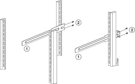
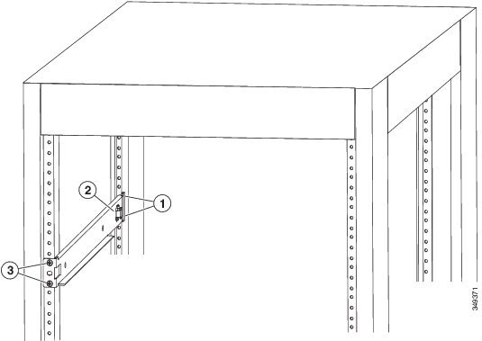

        Step 1   Attach the bottom-support rails on the rack as follows:
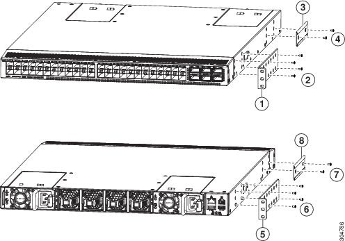
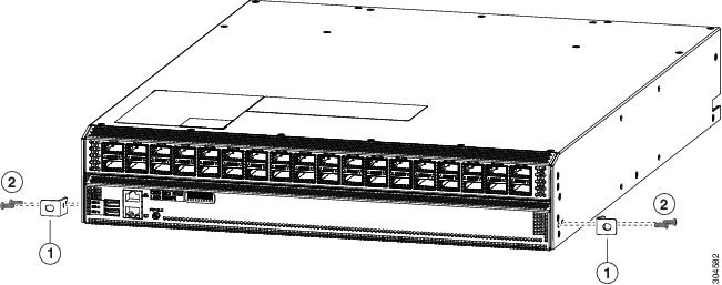
        1. Position an expanding set of bottom-support brackets on the rack with each end touching a vertical mounting rail on the front and rear of the rack. Ensure that the chassis stop is on the side of the chassis where you plan to position the power supply and fan modules when you install the chassis (see the following figure).
          Figure 5. Positioning an Expanding Bottom-Support Rail Set


          1

          2 screws holding one end of the bottom-support bracket to the rear of the rack

          3

          2 screws holding the front end of the bottom-support bracket to the front side of the rack

          2

          Chassis stop on the expanding bottom-support bracket

        2. Holding the bottom-support rail level, attach the rail to the front and rear vertical mounting rails using four customer-supplied screws that are appropriate for the rack (use two screws for each vertical mounting rail), and tighten each screw to the appropriate torque setting for that screw.

          Typically, you use one of the following types of screws and the associated torque settings when tightening them:

          • M4 screws—use 12 in-lb (1.36 N·m) of torque

          • M6 screws—use 40 in-lb (4.5 N·m) of torque

          • 10-32 screws— use 20 in-lb (2.26 N·m) of torque

          If the rack requires another type of screw, use the appropriate torque setting for that type of screw.

        3. Repeat Steps 1a and 1b to attach the other expanding bottom-support rail to the other side of the rack at the same level as the attached bottom-support rail.
          Note   

          Verify that the two sets of bottom-support rails are level with each other before going to the next step.

        Step 2   Attach two front-mount brackets to the sides of the chassis as follows:
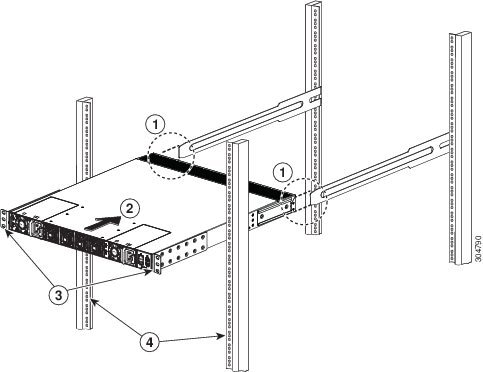
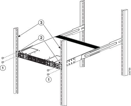
        1. Align the two holes in one side of a front-mount bracket to two holes on the left or right side of the chassis as shown in the following figure.
          Figure 6. Aligning and attaching Front-Mount Brackets to the Chassis


          1

          Front rack-mount bracket

          2

          2 M4 x 6 mm screws

        2. Use two M4 x 6 mm screws to attach the bracket to the chassis and tighten each screw to 12 in-lb (1.36 N·m) of torque.
        3. Repeat Steps 2a and 2b to attach the other front-mount bracket to the other side of the chassis.
        Step 3   Install the chassis in the rack as follows:
        1. Slide the power supply end of the chassis onto the installed bottom-support rails as shown in the following figure.

          When you have fully pushed the chassis all the way onto the bottom-support rails, the chassis stops on the bottom-support rails insert into the chassis notches and the front-mount brackets touch the front vertical mounting rails.

          Figure 7. Sliding the Chassis onto the Bottom-Support Rails


          1

          Slide the power-supply end of the chassis onto the bottom-support rails so that the chassis stops insert into the chassis notches.

          3

          Receiving notches on each side of the chassis for the chassis stops on the bottom-support rails.

          2

          Chassis stops

          4

          Rack-mount screw

        2. Use two screws that are appropriate for the rack to attach the front-mount brackets to the rack (one screw for each mounting bracket).

          Typically, you use one of the following types of screws and the associated torque settings when tightening them:

          • M4 screws—use 12 in-lb (1.36 N·m) of torque

          • M6 screws—use 40 in-lb (4.5 N·m) of torque

          • 10-32 screws— use 20 in-lb (2.26 N·m) of torque

          If the rack requires another type of screw, use the appropriate torque setting for that type of screw.


        Starting the Switch

        To power up the switch, follow these steps:

        Before You Begin
        • Verify that the switch is fully installed and secured to a rack.

        • Verify that the switch is adequately grounded to the facility earth ground or to a grounded rack.

        • Verify that all of the fan and power supply modules are installed in the chassis. If the chassis has only one power supply, there must be a blank module (N2200-P-BLNK) in the open power supply slot to maintain the designed airflow.

        • If you are using a DC power source, verify that the circuit is shut off at a circuit breaker.


          Step 1   If the switch has AC power supplies, connect those power supplies to an AC power source as follows:
          1. Verify that the AC power source is turned off at the circuit breaker.
          2. Plug the power cable into the power receptacle on the power supply.
          3. Attach the other end of the power cable to the AC power source.
          4. Turn on the power at the circuit breaker.
          5. Verify that the power supply is functioning by making sure that the OK LED turns green and the FAULT LED is off.
          Step 2   If the switch has DC power supplies, connect those power supplies to a DC power source as follows:
          1. Verify that the DC power source is turned off at the circuit breaker.
          2. Remove the clear plastic safety cover that prevents you from touching the negative (-) and positive (+) terminals on the power supply.
          3. Connect a negative cable from the power source to the left (-) terminal on the power supply.
          4. Connect a positive cable from the power source to the right (+) terminal on the power supply.
          5. Clip on the clear plastic safety cover over the power supply terminals to prevent accidental touching of these terminals.
          6. Turn on the power at the circuit breaker.
          7. Verify that the power supply is functioning by making sure that the OK LED turns green and the FAULT LED is off.
          Step 3   Listen for the fans; they should begin operating when the power cable is plugged in.
          Step 4   After the switch boots, verify that the following LEDs are on:
          • Power supply LED—lit and green

            If not green, try removing the module part way from its slot and reinstalling it.

          • Fan LED—lit and green

            If not green, try removing the module part way from its slot and reinstalling it.

          • System Status LED—lit and green (if this LED is orange or red, then one or more environmental monitors is reporting a problem.)

          • Link LEDs for the Ethernet connector—Off