Configuring the Cisco Nexus 2000 Series Fabric Extender

This section describes how to configure the Fabric Extender.

Information About Cisco Nexus 2000 Series Fabric Extender

FEX in Active-Active Mode

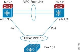
Beginning with Cisco NX-OS Release 7.2(0)D1(1) , a Fabric Extender can support connections to two Cisco Nexus 7000 Series switches in active-active mode using a vPC.

A Fabric Extender in active-active (FEX-AA) mode:

  • Uses a vPC to provide a seamless fail-over and fast convergence when one of the switches fail.

  • Supports traffic across both switches to maintain efficiency.

Figure 1. FEX Active-Active


Configuration Synchronization and FEX-AA

The vPC configuration synchronization feature can be used for FEX-AA. Configuration synchronization allows you to synchronize the configuration between a pair of switches in a network. You use a switch profile to create a configuration file that is applied locally and used to synchronize the configuration to the peer.

Guidelines and Limitations for FEX-AA

The following are guidelines and limitations for FEX-AA:

  • FEX-AA is not supported on vPC+ deployments.

  • Before performing switchover manually, ensure the switch and fabric extenders are not undergoing any configuration change or hardware replacement.

  • Configuring FEX-AA across two VDCs on the same chassis is not supported.

  • FEXs configured in AA mode cannot have host interfaces configured in L3 mode.

  • Straight-Through FEX and Active-Active FEX cannot exist on a same ASIC instance.

  • Both Cisco Nexus 7000 Series switches can configure the FEX.

  • Both Cisco Nexus 7000 Series switches must configure the FEX in the same way so that the fex-id is the same for each.

  • The configuration of host ports and host port-channels behind the FEX in AA mode must be the same on both the Cisco Nexus 7000 switches .

  • The FEX image can be downloaded from either Cisco Nexus 7000 Series switch.

Managing the Fabric Extender Feature Set

You can install and manage the Fabric Extender feature set.

SUMMARY STEPS

  1. Installing the Fabric Extender Feature Set
  2. Enabling the Fabric Extender Feature Set
  3. (Optional) Disallowing the Fabric Extender Feature Set

DETAILED STEPS


Step 1

Installing the Fabric Extender Feature Set

Step 2

Enabling the Fabric Extender Feature Set

Step 3

(Optional) Disallowing the Fabric Extender Feature Set


Installing the Fabric Extender Feature Set


Note


You must enable the Fabric Extender feature set in the default virtual device context (VDC). Once enabled in the default VDC, the FEX can belong to any VDC and can be configured from those VDCs. A single Fabric Extender belongs exclusively to a single VDC.


Before you begin

Ensure that you are in the default VDC.

Ensure that you have disabled the Intrusion Detection System (IDS) reserved addresses check (it is disabled by default). Use the show hardware ip verify command and look for the string "address reserved" in the output. If the IDS reserved addresses check is enabled, disable it with the no hardware ip verify address reserved command.

SUMMARY STEPS

  1. configure terminal
  2. install feature-set fex
  3. exit

DETAILED STEPS

  Command or Action Purpose

Step 1

configure terminal

Example:

switch# configure terminal
switch(config)# 

Enters global configuration mode.

Step 2

install feature-set fex

Example:

switch(config)# install feature-set fex

Installs the Fabric Extender feature set in the default VDC.

To uninstall the Fabric Extender feature set, use the no install feature-set fex command. Before you can uninstall the feature set, you must ensure the following:

  • The feature set must be installed in the default VDC.

  • The feature set must not be enabled in any VDC.

Step 3

exit

Example:

switch(config)# exit
switch# 

Exits global configuration mode.

Enabling the Fabric Extender Feature Set

You can enable the installed Fabric Extender feature set in any VDC on the device.

Before you begin

Ensure that you have installed the Fabric Extender feature set in the default VDC.

Ensure that you are in the correct VDC or use the switchto vdc command.

SUMMARY STEPS

  1. configure terminal
  2. feature-set fex
  3. exit

DETAILED STEPS

  Command or Action Purpose

Step 1

configure terminal

Example:

switch# configure terminal
switch(config)# 

Enters global configuration mode.

Step 2

feature-set fex

Example:

switch(config)# feature-set fex

Enables the Fabric Extender feature set. The feature set must be installed before it shows as an option to this command.

To disable the Fabric Extender feature set, use the no feature-set fex command. Before you can disable a feature set, you must install the feature set in the default VDC.

Note


The no feature-set fex command might take some time to complete if the size of the configuration is very large. The command cleans up all of the configurations associated with the Fabric Extender feature set.

Step 3

exit

Example:

switch(config)# exit
switch# 

Exits global configuration mode.

Disallowing the Fabric Extender Feature Set

By default, when you install the Fabric Extender feature set, it is allowed in all VDCs. You can disallow the installed Fabric Extender feature set in a specific VDC on the device.

Before you begin

Ensure that you have installed the feature set in the default VDC.

Ensure that you have not enabled the feature set in the specified VDC.

SUMMARY STEPS

  1. configure terminal
  2. vdc vdc_ID
  3. no allow feature-set fex
  4. end

DETAILED STEPS

  Command or Action Purpose

Step 1

configure terminal

Example:

switch# configure terminal
switch(config)# 

Enters global configuration mode.

Step 2

vdc vdc_ID

Example:

switch(config)# vdc 1

Specifies a VDC and enters VDC configuration mode.

Step 3

no allow feature-set fex

Example:

switch(config-vdc)# no allow feature-set fex

Disallows the feature set in the VDC. You cannot disallow a feature set that is enabled in the specified VDC.

By default, the installed Fabric Extender feature set is allowed in all VDCs on the device. You can disallow a feature set in a specific VDC. Subsequently, you can change the status back to allowed with the allow feature-set fex command.

Step 4

end

Example:

switch(config-vdc)# end
switch# 

Exits VDC configuration mode and returns to EXEC mode.

Associating a Fabric Extender to a Fabric Interface

Associating a Fabric Extender to a Port Channel

Before you begin

Ensure that you have enabled the Fabric Extender feature.

SUMMARY STEPS

  1. configure terminal
  2. interface port-channel channel
  3. switchport mode fex-fabric
  4. fex associate FEX-number
  5. (Optional) show interface port-channel channel fex-intf

DETAILED STEPS

  Command or Action Purpose

Step 1

configure terminal

Example:

switch# configure terminal
switch(config)# 

Enters global configuration mode.

Step 2

interface port-channel channel

Example:

switch(config)# interface port-channel 4
switch(config-if)# 

Specifies a port channel to configure.

Step 3

switchport mode fex-fabric

Example:

switch(config-if)# switchport mode fex-fabric

Sets the port channel to support an external Fabric Extender.

Step 4

fex associate FEX-number

Example:

switch(config-if)# fex associate 101

Associates a FEX number to the Fabric Extender unit attached to the interface. The range is from 100 to 199.

Step 5

(Optional) show interface port-channel channel fex-intf

Example:

switch# show interface port-channel 4 fex-intf
(Optional)

Displays the association of a Fabric Extender to a port channel interface.

Example

This example shows how to associate the Fabric Extender to a port channel interface on the parent device:

switch# configure terminal
switch(config)# interface ethernet 1/28
switch(config-if)# channel-group 4
switch(config-if)# no shutdown
switch(config-if)# exit
switch(config)# interface ethernet 1/29
switch(config-if)# channel-group 4
switch(config-if)# no shutdown
switch(config-if)# exit
switch(config)# interface ethernet 1/30
switch(config-if)# channel-group 4
switch(config-if)# no shutdown
switch(config-if)# exit
switch(config)# interface ethernet 1/31
switch(config-if)# channel-group 4
switch(config-if)# no shutdown
switch(config-if)# exit
switch(config)# interface port-channel 4
switch(config-if)# switchport
switch(config-if)# switchport mode fex-fabric
switch(config-if)# fex associate 101

Tip


As a best practice, only enter the fex associate command from the port channel interface, not from the physical interface.


Note


When adding physical interfaces to port channels, all configurations on the port channel and physical interface must match.


This example shows how to display the association of the Fabric Extender and the parent device:

switch# show interface port-channel 4 fex-intf
Fabric           FEX
Interface        Interfaces
---------------------------------------------------
Po4              Eth101/1/48   Eth101/1/47   Eth101/1/46   Eth101/1/45
                 Eth101/1/44   Eth101/1/43   Eth101/1/42   Eth101/1/41
                 Eth101/1/40   Eth101/1/39   Eth101/1/38   Eth101/1/37
                 Eth101/1/36   Eth101/1/35   Eth101/1/34   Eth101/1/33
                 Eth101/1/32   Eth101/1/31   Eth101/1/30   Eth101/1/29
                 Eth101/1/28   Eth101/1/27   Eth101/1/26   Eth101/1/25
                 Eth101/1/24   Eth101/1/23   Eth101/1/22   Eth101/1/21
                 Eth101/1/20   Eth101/1/19   Eth101/1/18   Eth101/1/17
                 Eth101/1/16   Eth101/1/15   Eth101/1/14   Eth101/1/13
                 Eth101/1/12   Eth101/1/11   Eth101/1/10   Eth101/1/9
                 Eth101/1/8    Eth101/1/7    Eth101/1/6    Eth101/1/5
                 Eth101/1/4    Eth101/1/3    Eth101/1/2    Eth101/1/1
 

Disassociating a Fabric Extender from an Interface

Before you begin

Ensure that you have enabled the Fabric Extender feature.

SUMMARY STEPS

  1. configure terminal
  2. interface { ethernet slot/ port | port-channel channel}
  3. no fex associate

DETAILED STEPS

  Command or Action Purpose

Step 1

configure terminal

Example:

switch# configure terminal
switch(config)# 

Enters global configuration mode.

Step 2

interface { ethernet slot/ port | port-channel channel}

Example:

switch(config)# interface port-channel 4
switch(config-if)# 

Specifies the interface to configure. The interface can be an Ethernet interface or a port channel.

Step 3

no fex associate

Example:

switch(config-if)# no fex associate

Disassociates the Fabric Extender unit attached to the interface.

Associating a Fabric Extender to an F-Series Module

Before you begin

Ensure that you have installed and enabled the Fabric Extender feature set.

  • switch# configure terminal

  • switch(config)# install feature-set fex

  • switch(config)# feature-set fex


Note


F-Series modules (except F1 Series) are supported only by the following FEX devices:

  • 2248TP

  • 2248TP-E

  • 2248PQ

  • 2348UPQ

  • 2348TQ

  • 2232TP

  • 2232PP

  • 2232TM

  • 2224TP

  • B22-IBM

  • B22-HP


Note


Restriction for F2-Series Linecards in an F2 VDC:

Each port in the ASIC has an index. Allow only ports with similar indices across ASICs to be added to a port channel.

For example, if port 1 has an index of 1 and port 2 has an index of 2, the following ports are supported and not supported:

  • Supported: Port 1 of ASIC 1 and port 1 of ASIC 2 are added to a port channel.

  • Not supported (For F2-series): Port 1 of ASIC 1 and port 2 of ASIC 2 to form a port channel.

A set of ports from an ASIC that has an index sub-set S, such as {1,2,4}, is allowed to be added to a port channel only if the port channel has an equivalent or an empty set.


SUMMARY STEPS

  1. vdc switch
  2. limit-resource module-type [f2e | f3]
  3. interface ethernet mod-number port-range
  4. allocate interface ethernet slot-port
  5. switchport mode fex -fabric
  6. fex associate FEX chassis number
  7. channel-group port-channel number
  8. no shutdown
  9. int port port-channel number
  10. no shutdown

DETAILED STEPS

  Command or Action Purpose

Step 1

vdc switch

Example:

switch(config)# vdc switch

Specifies the VDC.

Step 2

limit-resource module-type [f2e | f3]

Example:

switch(config)# limit-resource module-type f2e

Specifies the module type.

Step 3

interface ethernet mod-number port-range

Example:

switch(config)# interface ethernet 1/1

Specifies the interface.

Step 4

allocate interface ethernet slot-port

Example:

switch(config)# allocate interface ethernet 1

Allocates the F2-Series interfaces to VDC.

Step 5

switchport mode fex -fabric

Example:

switch(config-if)# switchport mode fex -fabric

Specifies the FEX.

Step 6

fex associate FEX chassis number

Example:

switch(config-if)# fex associate 101

Specifies the chassis.

Step 7

channel-group port-channel number

Example:

switch(config-if)# channel-group 1

Specifies the port channel number.

Step 8

no shutdown

Example:

switch(config-if)# no shutdown

Brings up the port.

Step 9

int port port-channel number

Example:

switch(config-if)# int port 1

Specifies the port channel.

Step 10

no shutdown

Example:

switch(config-if)# no shutdown

Brings up the port channel.

Configuring Fabric Extender Global Features

You can configure global features on the Fabric Extender.

Before you begin

Ensure that you have enabled the Fabric Extender feature set.

SUMMARY STEPS

  1. configure terminal
  2. fex FEX-number
  3. (Optional) description desc
  4. (Optional) no description
  5. (Optional) no type
  6. (Optional) serial serial
  7. (Optional) no serial

DETAILED STEPS

  Command or Action Purpose

Step 1

configure terminal

Example:

switch# configure terminal
switch(config)# 

Enters global configuration mode.

Step 2

fex FEX-number

Example:

switch(config)# fex 101
switch(config-fex)# 

Enters FEX configuration mode for the specified Fabric Extender. The range of the FEX-number is from to 199.

Step 3

(Optional) description desc

Example:

switch(config-fex)# description Rack7A-N2K
(Optional)

Specifies the description. The default is the string FEXxxxx where xxxx is the FEX number. If the FEX number is 123, the description is FEX0123.

Step 4

(Optional) no description

Example:

switch(config-fex)# no description
(Optional)

Deletes the description.

Step 5

(Optional) no type

Example:

switch(config-fex)# no type
(Optional)

Deletes the FEX type. When a Fabric Extender is connected to the fabric interfaces and does not match the configured type that is saved in the binary configuration on the parent switch, all configurations for all interfaces on the Fabric Extender are deleted.

Step 6

(Optional) serial serial

Example:

switch(config-fex)# serial JAF1339BDSK
(Optional)

Defines a serial number string. If this command is configured, a switch allows the corresponding chassis ID to associate (using the fex associate command) only if the Fabric Extender reports a matching serial number string.

Caution


Configuring a serial number that does not match the specified Fabric Extender forces the Fabric Extender offline.

Step 7

(Optional) no serial

Example:

switch(config-fex)# no serial
(Optional)

Deletes the serial number string.

Enabling DSCP to Queue Mapping

For Cisco NX-OS Release 6.2(2) and later releases, the Cisco Fabric Extenders support Layer 3 protocol adjacencies on host interfaces (HIFs) and DSCP to queue mapping. Before Cisco NX-OS Release 6.2(2), you can configure a Fabric Extender (FEX) port as a Layer 3 interface for host connectivity, but not for routing. See the Configuring the Cisco Nexus 2000 Series Fabric Extender for more information about fabric extenders.

Before Cisco NX-OS 6.2(2), the Fabric Extender cannot participate in a routing protocol adjacency with a device attached to its port. Only a static direct route is supported. This restriction applies to both of the following supported connectivity cases:
  • Switch virtual interfaces (SVI) with Fabric Extender single port or portchannel in Layer 2 mode.

  • Fabric Extender port or portchannel in Layer 3 mode.

SUMMARY STEPS

  1. configure terminal
  2. hardware qos dscp-to-queue ingress module type {all | f-series | m-series}
  3. (Optional) show hardware qos dscp-to-queue ingress
  4. (Optional) copy running-config startup-config

DETAILED STEPS

  Command or Action Purpose

Step 1

configure terminal

Example:

switch(config)# configure terminal

Enters global configuration mode.

Step 2

hardware qos dscp-to-queue ingress module type {all | f-series | m-series}

Example:

switch(config)# hardware qos dscp-to-queue ingress module type m-series

Enables the dscp-to-queue mapping on the specified module(s).

Step 3

(Optional) show hardware qos dscp-to-queue ingress

Example:

switch(config)# show hardware qos dscp-to-queue ingress
(Optional)

Displays information about the status of dscp-to-queue mapping in ingress direction.

Step 4

(Optional) copy running-config startup-config

Example:

switch(config)# copy running-config startup-config
(Optional)

Saves the running configuration to the startup configuration.

Configuration Examples

This section contains examples of FEX configurations.

Configuring a FEX with a Layer 3 Host Interface

This example shows how to configure a Fabric Extender with a Layer 3 host interface (at the interface level, subinterface level, port channel level, and port channel subinterface level):

Layer 3 Configuration Layer 3 Subinterface Configuration
config t
interface ethernet 101/1/1
no switchport
ip address 192.0.1.1/24
Mtu 9000
no shutdown
config t
interface ethernet 101/1/1.12
ip address 192.0.2.1/24
encapsulation dot1Q 12
mtu 850
no shutdown
Layer 3 Host Interface Port Channel Configuration Layer 3 Host Interface Port Channel Subinterface Configuration
config t
interface ethernet 101/1/1-2
no switchport
channel-group 12
no shutdown

interface port-channel 12
ip address 192.0.3.1/24
mtu 2000
no shutdown
config t
interface ethernet 101/1/1-2
no switchport
channel-group 12
no shutdown

interface port-channel 12.14
ip address 192.0.4.1/24
encapsulation dot1Q 14
mtu 1700
no shutdown

Note


The VLAN used in the Layer 3 host interface (HIF) or host interface port channel (HIFPC) subinterface has only local significance to its parent interface. The same VLAN ID can be reused between Layer 3 subinterfaces in the same switch or VDC.


Configuring a Host Interface in a vPC Topology Connected to Two FEXs

This example shows how to configure a host vPC with a FEX (host vPC attached to two different FEXs):


Note


The switchport trunk allowed vlan vlan-list command is not supported on FEX fabric interfaces.


Switch 1 Configuration Switch 2 Configuration
config t
feature lacp
int e101/1/1-2
channel-group 12 mode active
no shutdown

int port-channel12
switchport
  switchport mode trunk
  switchport trunk allowed vlan 1-20
vpc 10
config t
feature lacp
int e101/1/1-2
channel-group 12 mode active
no shutdown

int port-channel12
switchport
  switchport mode trunk
  switchport trunk allowed vlan 1-20
vpc 10

Dual-Homing of a Server to a FEX with FabricPath


Note


Cisco Nexus 7000 Series switches do not support dual-homing.
To configure FabricPath interfaces for two switches that are connected with FabricPath, perform the following tasks on each switch:
  • Enable FabricPath on each switch.

  • Configure the interfaces that you want to designate as FabricPath interfaces.

  • Set the STP priority device to 8192 on all FabricPath Layer 2 gateway devices.

  • (Optional) Set the STP domain ID for each of the separate STP domains that are connected to the FabricPath network.

  • (Optional) Configure a FEX switch ID.

To configure FabricPath interfaces, follow these steps:

  1. (Optional) Enable FabricPath on each switch.

    switch# config terminal
    switch(config)# feature fabricpath
    switch(config-lldp)# exit
    switch(config)# 
  2. After you enable FabricPath on the switch, configure the specified interface as FabricPath interfaces.

    switch(config)# interface ethernet 1/2
    switch(config-if)# switchport mode fabricpath 
    switch(config-if)# exit
    switch(config)# 
  3. Configure the STP priority for all Rapid PVST+ VLANs as 8192.

    switch# config terminal 
    switch(config)# spanning-tree vlan 11-20 priority 8192
    switch(config)# 
  4. Configure the STP priority for all MST instances as 8192.

    switch# config terminal 
    switch(config)# spanning-tree mst 1-5 priority 8192
    switch(config)# 
  5. (Optional) Configure the STP domain ID on each FabricPath Layer 2 gateway switch attached to the FabricPath network.

    switch# config terminal 
    switch(config)# spanning-tree domain 5
    switch(config)
  6. (Optional) Configure the FEX switch ID.


    Note


    See the Cisco Nexus 7000 Series NX-OS Interfaces Configuration Guide for information on configuring FEX.


    Note


    FEX VPC+ configurations are supported only on F2-Series modules.


    If you are setting up an initial FEX VPC+ configuration on an F2-Series module, follow these steps:

    1. In the VPC domain configuration mode, enable partial DF mode with the fabricpath multicast load-balance command.

    2. If disabled, enable TRILL style mac-address learning with the mac address-table core-port-learning command.

    3. In the VPC domain configuration mode, configure the emulated switch ID with the fabricpath switchid switchid# command.

    4. On each of the VPC/VPC+ peer link interfaces in interface configuration mode, enter theswitchport mode fabricpath command.

    5. On each VPC/VPC+ peer link port channel, enter the VPC peer-link command.

    6. Configure the VPC ID with the vpc vpcid command.

    If you are changing an existing FEX VPC configuration to a FEX VPC+ configuration on an F2-Series module, follow these steps:

    1. In the VPC domain configuration mode, enable partial DF mode with the fabricpath multicast load-balance command.

    2. If disabled, enable trill style mac-address learning with the mac address-table core-port-learning command.

    3. In the VPC domain configuration mode, configure the emulated switch ID with the fabricpath switchid switchid# command.

  7. Copy the configuration.

    switch(config)# copy running-config startup-config
    switch(config)#

Configuring a FEX in Active-Active Mode

This example shows how to configure a FEX in active-active (FEX-AA) mode:

Switch 1 Configuration Switch 2 Configuration
int eth 1/1
channel-group 1
int po1
switchport
switchport mode fex-fabric
fex associate 101
vpc 10
int eth 2/2
channel-group 2
int po2
switchport
switchport mode fex-fabric
fex associate 101
vpc 10

Note


  • The chassis number (fex-id) for both switches must be the same.

  • Configuring FEX-AA across two VDCs on the same chassis is not supported.

  • FEX-AA does not support Layer 3 interfaces.


Verifying the Status of DSCP-to-queue Mapping

The following sample output from the show hardware qos dscp-to-queue ingress command displays the status of DSCP-to-queue mapping enabled in ingress direction on F-series modules:


Switch# show hardware qos dscp-to-queue ingress

status: Enabled
module_type : f-series

Verifying the Configuration

This section describes how to display the configuration of the Fabric Extender and verify the chassis hardware status.

Verifying the Fabric Extender Configuration

Use the following commands to display configuration information about the defined interfaces on a Fabric Extender:

Command or Action

Purpose

show fex [ FEX-number] [ detail]

Displays information about a specific Fabric Extender or all attached units.

show interface type number fex-intf

Displays the Fabric Extender ports that are pinned to a specific switch interface.

show interface fex-fabric

Displays the switch interfaces that have detected a Fabric Extender uplink.

show interface ethernet number transceiver [ fex-fabric]

Displays the SFP+ transceiver and diagnostic optical monitoring (DOM) information for the Fabric Extender uplinks.

show feature-set

Displays the status of the feature sets on the device.

Configuration Examples for the Fabric Extender

This example shows how to display all the attached Fabric Extender units:

This example shows how to display the detailed status of a specific Fabric Extender:

This example shows how to display the Fabric Extender interfaces pinned to a specific switch interface:

This example shows how to display the switch interfaces that are connected to a Fabric Extender uplink:

This example shows how to display the SFP+ transceiver and diagnostic optical monitoring (DOM) information for Fabric Extender uplinks for an SFP+ transceiver that is plugged into the parent switch interface:

switch# show interface ethernet 1/40 transceiver
Ethernet1/40
    sfp is present
    name is CISCO-MOLEX INC
    part number is 74752-9026
    revision is A0
    serial number is MOC13321057
    nominal bitrate is 12000 MBits/sec
    Link length supported for copper is 3 m(s)
    cisco id is --
    cisco extended id number is 4
 

This example shows how to display the SFP+ transceiver and DOM information for Fabric Extender uplinks for an SFP+ transceiver that is plugged into the uplink port on the Fabric Extender:

switch# show interface ethernet 1/40 transceiver fex-fabric
Ethernet1/40
    sfp is present
    name is CISCO-MOLEX INC
    part number is 74752-9026
    revision is A0
    serial number is MOC13321057
    nominal bitrate is 12000 MBits/sec
    Link length supported for 50/125mm fiber is 0 m(s)
    Link length supported for 62.5/125mm fiber is 0 m(s)
    cisco id is --
    cisco extended id number is 4
 

Verifying the Chassis Management Information

Use the following to display configuration information used on the switch supervisor to manage the Fabric Extender.

Command or Action

Purpose

show environment fex {all | FEX-number} [temperature | power | fan]

Displays the environmental sensor status.

show inventory fex FEX-number

Displays inventory information for a Fabric Extender.

show module fex [FEX-number]

Displays module information about a Fabric Extender.

show sprom fex FEX-number {all | backplane | powersupply ps-num} | all

Displays the contents of the serial PROM (SPROM) on the Fabric Extender. The unit of the power for the show sprom command is displayed in centi-amperes.

Configuration Examples for Chassis Management

This example shows how to display the module information about all connected Fabric Extender units:

This example shows how to display the inventory information about a specific Fabric Extender:

switch# show inventory fex 101
NAME: "FEX 101 CHASSIS", DESCR: "N2K-C2248TP-1GE  CHASSIS"
PID: N2K-C2248TP-1GE   , VID: V00 , SN: SSI13380FSM

NAME: "FEX 101 Module 1", DESCR: "Fabric Extender Module: 48x1GE, 4x10GE Supervisor"
PID: N2K-C2248TP-1GE   , VID: V00 , SN: JAF1339BDSK

NAME: "FEX 101 Fan 1", DESCR: "Fabric Extender Fan module"
PID: N2K-C2248-FAN     , VID: N/A , SN: N/A

NAME: "FEX 101 Power Supply 2", DESCR: "Fabric Extender AC power supply"
PID: NXK-PAC-400W      , VID:  000, SN:      LIT13370QD6
 

This example shows how to display the environment status for a specific Fabric Extender:

switch# show environment fex 101


Temperature Fex 101:
-----------------------------------------------------------------
Module   Sensor     MajorThresh   MinorThres   CurTemp     Status
                    (Celsius)     (Celsius)    (Celsius)
-----------------------------------------------------------------
1        Outlet-1   60            50           33          ok
1        Outlet-2   60            50           38          ok
1        Inlet-1    50            40           35          ok
1        Die-1      100           90           44          ok


Fan Fex: 101:
------------------------------------------------------
Fan             Model                Hw         Status
------------------------------------------------------
Chassis         N2K-C2148-FAN        --         ok
PS-1            --                   --         absent
PS-2            NXK-PAC-400W         --         ok


Power Supply Fex 101:
---------------------------------------------------------------------------
Voltage: 12 Volts
-----------------------------------------------------
PS  Model                Power       Power     Status
                         (Watts)     (Amp)
-----------------------------------------------------
1   --                        --        --     --
2   NXK-PAC-400W            4.32      0.36     ok


Mod Model                Power     Power       Power     Power       Status
                         Requested Requested   Allocated Allocated
                         (Watts)   (Amp)       (Watts)   (Amp)
--- -------------------  -------   ----------  --------- ----------  ----------
1    N2K-C2248TP-1GE     0.00      0.00        0.00      0.00        powered-up


Power Usage Summary:
--------------------
Power Supply redundancy mode:                 redundant

Total Power Capacity                                4.32 W

Power reserved for Supervisor(s)                    0.00 W
Power currently used by Modules                     0.00 W

                                                -------------
Total Power Available                               4.32 W
                                                -------------
 

This example shows how to display the SPROM for a specific Fabric Extender:

switch# show sprom fex 101 all
DISPLAY FEX 101 SUP sprom contents
Common block:
 Block Signature : 0xabab
 Block Version   : 3
 Block Length    : 160
 Block Checksum  : 0x1a1e
 EEPROM Size     : 65535
 Block Count     : 3
 FRU Major Type  : 0x6002
 FRU Minor Type  : 0x0
 OEM String      : Cisco Systems, Inc.
 Product Number  : N2K-C2248TP-1GE
 Serial Number   : JAF1339BDSK
 Part Number     : 73-12748-01
 Part Revision   : 11
 Mfg Deviation   : 0
 H/W Version     : 0.103
 Mfg Bits        : 0
 Engineer Use    : 0
 snmpOID         : 9.12.3.1.9.78.3.0
 Power Consump   : 1666
 RMA Code        : 0-0-0-0
 CLEI Code       : XXXXXXXXXTBDV00
 VID             : V00
Supervisor Module specific block:
 Block Signature : 0x6002
 Block Version   : 2
 Block Length    : 103
 Block Checksum  : 0x2686
 Feature Bits    : 0x0
 HW Changes Bits : 0x0
 Card Index      : 11016
 MAC Addresses   : 00-00-00-00-00-00
 Number of MACs  : 0
 Number of EPLD  : 0
 Port Type-Num   : 1-48;2-4
 Sensor #1       : 60,50
 Sensor #2       : 60,50
 Sensor #3       : -128,-128
 Sensor #4       : -128,-128
 Sensor #5       : 50,40
 Sensor #6       : -128,-128
 Sensor #7       : -128,-128
 Sensor #8       : -128,-128
 Max Connector Power: 4000
 Cooling Requirement: 65
 Ambient Temperature: 40

DISPLAY FEX 101 backplane sprom contents:
Common block:
 Block Signature : 0xabab
 Block Version   : 3
 Block Length    : 160
 Block Checksum  : 0x1947
 EEPROM Size     : 65535
 Block Count     : 5
 FRU Major Type  : 0x6001
 FRU Minor Type  : 0x0
 OEM String      : Cisco Systems, Inc.
 Product Number  : N2K-C2248TP-1GE
 Serial Number   : SSI13380FSM
 Part Number     : 68-3601-01
 Part Revision   : 03
 Mfg Deviation   : 0
 H/W Version     : 1.0
 Mfg Bits        : 0
 Engineer Use    : 0
 snmpOID         : 9.12.3.1.3.914.0.0
 Power Consump   : 0
 RMA Code        : 0-0-0-0
 CLEI Code       : XXXXXXXXXTDBV00
 VID             : V00
Chassis specific block:
 Block Signature : 0x6001
 Block Version   : 3
 Block Length    : 39
 Block Checksum  : 0x2cf
 Feature Bits    : 0x0
 HW Changes Bits : 0x0
 Stackmib OID    : 0
 MAC Addresses   : 00-0d-ec-e3-28-00
 Number of MACs  : 64
 OEM Enterprise  : 0
 OEM MIB Offset  : 0
 MAX Connector Power: 0
WWN software-module specific block:
 Block Signature : 0x6005
 Block Version   : 1
 Block Length    : 0
 Block Checksum  : 0x66
wwn usage bits:
 00 00 00 00 00 00 00 00
 00 00 00 00 00 00 00 00
 00 00 00 00 00 00 00 00
 00 00 00 00 00 00 00 00
 00 00 00 00 00 00 00 00
 00 00 00 00 00 00 00 00
 00 00 00 00 00 00 00 00
 00 00 00 00 00 00 00 00
 00 00 00 00 00 00 00 00
 00 00 00 00 00 00 00 00
 00 00 00 00 00 00 00 00
 00 00 00 00 00 00 00 00
 00 00 00 00 00 00 00 00
 00 00 00 00 00 00 00 00
 00 00 00 00 00 00 00 00
 00 00 00 00 00 00 00 00
 00 00 00 00 00 00 00 00
 00 00 00 00 00 00 00 00
 00 00 00 00 00 00 00 00
 00 00 00 00 00 00 00 00
 00 00 00 00 00 00 00 00
 00 00 00 00 00 00 00 00
 00 00 00 00 00 00 00 00
 00 00 00 00 00 00 00 00
 00 00 00 00 00 00 00 00
 00 00 00 00 00 00 00 00
 00 00 00 00 00 00 00 00
 00 00 00 00 00 00 00 00
 00 00 00 00 00 00 00 00
 00 00 00 00 00 00 00 00
 00 00 00 00 00 00 00 00
 00 00
License software-module specific block:
 Block Signature : 0x6006
 Block Version   : 1
 Block Length    : 16
 Block Checksum  : 0x86f
lic usage bits:
 ff ff ff ff ff ff ff ff

DISPLAY FEX 101 power-supply 2 sprom contents:
Common block:
 Block Signature : 0xabab
 Block Version   : 3
 Block Length    : 160
 Block Checksum  : 0x1673
 EEPROM Size     : 65535
 Block Count     : 2
 FRU Major Type  : 0xab01
 FRU Minor Type  : 0x0
 OEM String      : Cisco Systems Inc   NXK-PAC-400W
 Product Number  : NXK-PAC-400W
 Serial Number   :      LIT13370QD6
 Part Number     :         341
 Part Revision   : -037
 CLEI Code       : 5-01     01  000
 VID             :  000
 snmpOID         : 12336.12336.12336.12336.12336.12336.12374.12336
 H/W Version     : 43777.2
 Current         : 36
 RMA Code        : 200-32-32-32
Power supply specific block:
 Block Signature : 0x0
 Block Version   : 0
 Block Length    : 0
 Block Checksum  : 0x0
 Feature Bits    : 0x0
 Current 110v    : 36
 Current 220v    : 36
 Stackmib OID    : 0
 

Minimizing the Impact of a Disruptive Upgrade in an A-A FEX setup

You can upgrade Cisco Nexus 7000 Series Switches using two upgrade methods:

  • In-Service Software Upgrade (ISSU)

  • Non-ISSU/ Cold-Boot Upgrade

For more information on ISSU upgrades, refer to Cisco Nexus 7000 Series NX-OS Software Upgrade and Downgrade Guide. In some case, switch may require cold-boot upgrade methods for the upgrade.

This section provides the cold-boot upgrade procedure in an A-A FEX setup. This is recommended to minimize the disruption and reduce the issues caused after the upgrade.

A Non-ISSU upgrade for Cisco Nexus 7000 Series switches Peer 1 and Peer 2 in vPC with FEXs in active-active mode are involved in a disruptive upgrade.

Follow the below procedure to upgrade the vPC peers from one software image to a higher version minimize the disruption:

Procedure


Step 1

Ensure that both vPC peer 1 and peer 2 have same software image and running.

The FEX-AA has the same software image.

Step 2

Shut FEX Port Channel to bring down NIF (FEX uplink) on vPC peer 2.

The FEX remains online on vPC peer 1.

Step 3

Upgrade the vPC peer 2 switch with a new software image.

The FEX-AA has the old software image.

Step 4

Shut FEX Port Channel to bring down NIF (FEX uplink) on vPC peer 1.

Step 5

Bring up FEX Port Channel to up the NIF (FEX uplink) on vPC peer 2.

The FEX-AA is upgraded with the new software image.

Step 6

Ensure that the FEX-AA is upgraded with new software image and all AA FEX HIF interfaces are populated on vPC peer 2. Now upgrade the vPC peer 1 switch with the new software image.

FEX is down on vPC peer 1, FEX is online vPC peer 2, and FEX-AA is booted with the new software image.

Step 7

Bring up FEX Port Channel to up the NIF (FEX uplink) on vPC peer 1.

Step 8

Verify that the upgrade on vPC peer 1 and vPC peer 2 is completed successfully.

After the upgrade, both the vPC peer are online and start forwarding traffic and the FEX-AA version with the new software image.


Additional References

This section includes additional information that is related to configuring the Cisco Nexus 2000 Series Fabric Extender.

Related Documents

Related Topic

Document Title

Cisco NX-OS Licensing

Cisco NX-OS Licensing Guide

Virtual device contexts (VDC)

Cisco Nexus 7000 Series NX-OS Virtual Device Context Configuration Guide

Interface configuration

Cisco Nexus 7000 Series NX-OS Interfaces Configuration Guide

Command reference

Cisco Nexus 7000 Series Command References available at the following URL: http://www.cisco.com/en/US/products/ps9402/prod_command_reference_list.html

Feature History

This table lists the release history for this feature.

Table 1. Feature History for the Cisco Nexus 2000 Series Fabric Extender
Feature Name Releases Feature Information

vPC configuration synchronization

7.2(0)D1(1)

Added support for vPC configuration synchronization for FEX

Cisco Nexus 7000 Series FEX Fabric Active-Active

7.2(0)D1(1)

Added support for FEX Active-Active.

Feature set commands

5.1(1)

The Fabric Extender is enabled on the Cisco Nexus 7000 Series device with the install feature-set and feature-set commands.

Port channel and vPC support

5.2(1)

Support was added for port channels and the integration of vPC on the host interfaces.

Layer 3 support

5.2(1)

Layer 3 capability was added to the Fabric Extender host interface ports including IPv4 and IPv6 and IGMP snooping.

This table lists the supported line cards and FEXs.

Table 2. Supported Line cards and FEXs History
FEX and Line card Releases

Cisco Nexus B22 Fabric Extender for IBM

Cisco Nexus 2348UPQ Fabric Extender

Cisco Nexus 2348TQ Fabric Extender

7.2(0)D1(1)

Cisco Nexus B22 Fabric Extender for HP

Cisco Nexus 2248PQ Fabric Extender

6.2(2)

48-port, 100/1000 BASE-T (100-Mb/1-Gigabit) N2248TP-E

32-port 10-Gigabit SFP+ N2248TP-E

Support for M2 series modules

Cisco Nexus 2224TP Fabric Extender

Cisco Nexus 2232TM Fabric Extender

6.1(1)

48-port, 1/10-Gigabit F2-Series module (N7K-F248XP-25).

6.0(1)

Cisco Nexus 2248TP Fabric Extender

Cisco Nexus 2232PP Fabric Extender

5.2(1)

32-port, 10-Gigabit M1 module (N7K-M132XP-12)

32-port, 10-Gigabit M1 XL module (N7K-M132XP-12L).

5.1(1)