Cisco Nexus 1000V Getting Started Guide, Release 4.2(1) SV1(4)
Bias-Free Language
The documentation set for this product strives to use bias-free language. For the purposes of this documentation set, bias-free is defined as language that does not imply discrimination based on age, disability, gender, racial identity, ethnic identity, sexual orientation, socioeconomic status, and intersectionality. Exceptions may be present in the documentation due to language that is hardcoded in the user interfaces of the product software, language used based on RFP documentation, or language that is used by a referenced third-party product. Learn more about how Cisco is using Inclusive Language.
- Updated:
- January 31, 2011
Chapter: Configuring the Software Using the CLI
- CLI Software Configuration Process
- Setting Up the VSM Virtual Machine Using the CLI
- Verifying VSM Connectivity
- Creating a Cisco Nexus 1000V Plug-In on the vCenter Server
- Connecting to the vCenter Server
- Creating Required Port Profiles
- Configuring the System Port Profile for VSM-VEM Communication
- Example Configuration: System Profile for Critical Ports
- Configuring the Uplink Port Profile for VM Traffic
- Example Configuration: Uplink Profile for VM Traffic
- Configuring the Data Port Profile for VM Traffic
- Example Configuration: Data Profile for VM Traffic
- Adding an ESX 4.0 Host to the DVS
Configuring the Software Using the CLI
This chapter describes how to use the CLI to configure your Cisco Nexus 1000V software after it is installed on your ESX or ESXi 4.0 VMware server.

Note ![]() To install the Cisco Nexus 1000V software on your ESX or ESXi 4.0 VMware server, see the Cisco Nexus 1000V Software Installation Guide, Release 4.2(1)SV1(4).
To install the Cisco Nexus 1000V software on your ESX or ESXi 4.0 VMware server, see the Cisco Nexus 1000V Software Installation Guide, Release 4.2(1)SV1(4).
CLI Software Configuration Process
The following section will guide you through this process. After completing each procedure, return to this section to make sure you complete all required procedures in the correct sequence.
Step 1 ![]() Set up the VSM virtual machine using the "Setting Up the VSM Virtual Machine Using the CLI" procedure.
Set up the VSM virtual machine using the "Setting Up the VSM Virtual Machine Using the CLI" procedure.
Step 2 ![]() Do one of the following:
Do one of the following:
•![]() If you are configuring Layer 3 control, see the Domain Configuration section in the Cisco Nexus 1000V System Management Configuration Guide, Release 4.2(1)SV1(4), and then continue with the next step.
If you are configuring Layer 3 control, see the Domain Configuration section in the Cisco Nexus 1000V System Management Configuration Guide, Release 4.2(1)SV1(4), and then continue with the next step.
•![]() If you are not configuring Layer 3 control, continue with the next step.
If you are not configuring Layer 3 control, continue with the next step.
Step 3 ![]() Verify VSM connectivity using the "Verifying VSM Connectivity" procedure.
Verify VSM connectivity using the "Verifying VSM Connectivity" procedure.
Step 4 ![]() Add the Cisco Nexus 1000V license.
Add the Cisco Nexus 1000V license.
Note ![]() The software provides licenses for 16 CPU sockets for a period of 60 days. These licenses are used only if there are no permanent licenses installed on the VSM. The evaluation period of 60 days starts when you install the software.
The software provides licenses for 16 CPU sockets for a period of 60 days. These licenses are used only if there are no permanent licenses installed on the VSM. The evaluation period of 60 days starts when you install the software.
If you have purchased licenses, see the Cisco Nexus 1000V License Configuration Guide, Release 4.2(1)SV1(4).
Step 5 ![]() Create a Cisco Nexus 1000V plug-in using the "Creating a Cisco Nexus 1000V Plug-In on the vCenter Server" procedure.
Create a Cisco Nexus 1000V plug-in using the "Creating a Cisco Nexus 1000V Plug-In on the vCenter Server" procedure.
Step 6 ![]() Connect to vCenter Server using the "Connecting to the vCenter Server" procedure.
Connect to vCenter Server using the "Connecting to the vCenter Server" procedure.
Step 7 ![]() Create the required VLANs using the " Creating VLANs" procedure on page 2-7.
Create the required VLANs using the " Creating VLANs" procedure on page 2-7.
Step 8 ![]() Use the following procedures to create the required port profiles.
Use the following procedures to create the required port profiles.
•![]() "Configuring the System Port Profile for VSM-VEM Communication" procedure.
"Configuring the System Port Profile for VSM-VEM Communication" procedure.
•![]() "Configuring the Uplink Port Profile for VM Traffic" procedure
"Configuring the Uplink Port Profile for VM Traffic" procedure
•![]() "Configuring the Data Port Profile for VM Traffic" procedure
"Configuring the Data Port Profile for VM Traffic" procedure
Step 9 ![]() Add the host to the DVS using the "Adding an ESX 4.0 Host to the DVS" procedure.
Add the host to the DVS using the "Adding an ESX 4.0 Host to the DVS" procedure.
Step 10 ![]() You have completed this process. Return to the "Software Configuration Process" section on page 2-7
You have completed this process. Return to the "Software Configuration Process" section on page 2-7
Setting Up the VSM Virtual Machine Using the CLI
You can use this procedure to set up and save the VSM management access configuration with the CLI.
BEFORE YOU BEGIN
Before beginning this procedure, you must know or do the following:
•![]() You have the following information for configuring this Cisco Nexus 1000V VSM:
You have the following information for configuring this Cisco Nexus 1000V VSM:
–![]() The administrator password.
The administrator password.
–![]() The domain ID.
The domain ID.
–![]() The HA role.
The HA role.
- Primary for the first VSM in a redundant pair.
- Secondary for the second VSM in a redundant pair.
–![]() A switch name.
A switch name.
–![]() The Management 0 IP address and network mask.
The Management 0 IP address and network mask.
–![]() The type of SSH key to generate and the number of key bits.
The type of SSH key to generate and the number of key bits.
–![]() The SVS control mode (Layer 2 or Layer 3).
The SVS control mode (Layer 2 or Layer 3).
–![]() The control VLAN ID.
The control VLAN ID.
–![]() The packet VLAN ID.
The packet VLAN ID.
Note ![]() You can use the same VLAN ID for control, packet, and management, but if needed for flexibility, you can use separate VLAN IDs. Make sure that the network segment has adequate bandwidth and latency.
You can use the same VLAN ID for control, packet, and management, but if needed for flexibility, you can use separate VLAN IDs. Make sure that the network segment has adequate bandwidth and latency.
DETAILED STEPS
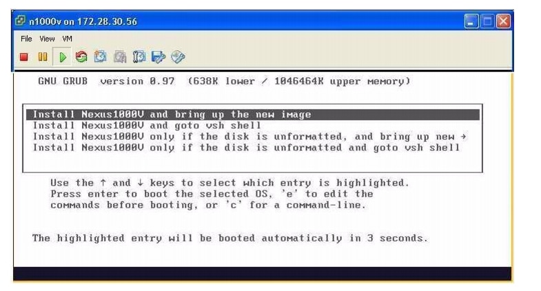
Step 1 ![]() Power on the VM, choose Install Cisco Nexus 1000V.
Power on the VM, choose Install Cisco Nexus 1000V.
The Cisco Nexus 1000V software starts.
Note ![]() It may take up to 5 minutes for the VM to power on.
It may take up to 5 minutes for the VM to power on.
One of the following displays.
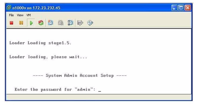
Step 2 ![]() When asked, enter and confirm the Administrator password.
When asked, enter and confirm the Administrator password.
Example:
---- System Admin Account Setup ----Confirm the password for
Enter the password for "admin": "admin":
Step 3 ![]() When asked, enter the domain ID.
When asked, enter the domain ID.
Example:
Enter the domain id<1-4095>: 152
Step 4 ![]() When asked, enter the HA role.
When asked, enter the HA role.
If you do not specify a role, standalone is assigned by default.
Example: standalone or primary
Enter HA role[standalone/primary/secondary]: primary
[#########################################] 100%
---- Basic System Configuration Dialog ----
This setup utility will guide you through the basic configuration of
the system. Setup configures only enough connectivity for management
of the system.
*Note: setup is mainly used for configuring the system initially,
when no configuration is present. So setup always assumes system
defaults and not the current system configuration values.
Press Enter at anytime to skip a dialog. Use ctrl-c at anytime
to skip the remaining dialogs.
Would you like to enter the basic configuration dialog (yes/no):
Example: Secondary
Enter HA role[standalone/primary/secondary]: secondary
Setting HA role to secondary will cause a system reboot. Are you sure (yes/no) ? :
Step 5 ![]() Do one of the following:
Do one of the following:
•![]() If you are setting up the primary/active VSM, go to Step 8.
If you are setting up the primary/active VSM, go to Step 8.
•![]() If you are setting up the secondary/standby VSM, then continue with the next step.
If you are setting up the secondary/standby VSM, then continue with the next step.
Step 6 ![]() If you have set the up the VSM VM to boot from the CD-ROM, and are installing the secondary VSM from the ISO image attached to your CD-ROM, remove the virtual CD-ROM now, so that VSM does not boot from the CD.
If you have set the up the VSM VM to boot from the CD-ROM, and are installing the secondary VSM from the ISO image attached to your CD-ROM, remove the virtual CD-ROM now, so that VSM does not boot from the CD.
This is necessary if you have set up the VSM VM to boot from the CD-ROM before the hard drive.
Step 7 ![]() If you are setting up the secondary/standby VSM, when prompted to reboot the VSM, answer yes.
If you are setting up the secondary/standby VSM, when prompted to reboot the VSM, answer yes.
The secondary VSM VM is rebooted and brought up in standby mode.
The password on the secondary VSM is synchronized with the password on the active/primary VSM.
Any configuration made on the active/primary VSM is now automatically synchronized with the standby.
Example: Secondary
Setting HA role to secondary will cause a system reboot. Are you sure (yes/no) ? :y
[########################################] 100%
HA mode set to secondary. Rebooting now...
You have completed this procedure for the secondary VSM. Return to the "CLI Software Configuration Process" section to proceed with the configuration.
Step 8 ![]() When asked if you want to enter the basic configuration dialog, answer yes.
When asked if you want to enter the basic configuration dialog, answer yes.
Example:
Would you like to enter the basic configuration dialog (yes/no): yes
Step 9 ![]() When asked to create another Login account, answer no.
When asked to create another Login account, answer no.
Example:
Create another login account (yes/no) [n]: no
Step 10 ![]() When asked to configure a read-only SNMP community string, answer no.
When asked to configure a read-only SNMP community string, answer no.
Example:
Configure read-only SNMP community string (yes/no) [n]: no
Step 11 ![]() When asked to configure a read-write SNMP community string, answer no.
When asked to configure a read-write SNMP community string, answer no.
Example:
Configure read-write SNMP community string (yes/no) [n]: no
Step 12 ![]() Enter a name for the switch.
Enter a name for the switch.
Example:
Enter the switch name: n1000v
Step 13 ![]() When asked to configure out-of-band management, answer yes and then enter the mgmt0 IPv4 address and subnet mask.
When asked to configure out-of-band management, answer yes and then enter the mgmt0 IPv4 address and subnet mask.
Example:
Continue with Out-of-band (mgmt0) management configuration? [yes/no] [y]: yes
Mgmt0 IPv4 address: 172.28.15.152
Mgmt0 IPv4 netmask: 255.255.255.0
Step 14 ![]() When asked to configure the default gateway, answer yes.
When asked to configure the default gateway, answer yes.
Example:
Configure the default-gateway: (yes/no) [y]: yes
IPv4 address of the default gateway : 172.23.233.1
Step 15 ![]() When asked to configure advanced IP options, answer no.
When asked to configure advanced IP options, answer no.
Example:
Configure Advanced IP options (yes/no)? [n]: no
Step 16 ![]() When asked to enable the Telnet service, answer yes.
When asked to enable the Telnet service, answer yes.
Example:
Enable the telnet service? (yes/no) [y]: yes
Step 17 ![]() When asked to enable the SSH service, answer yes and then enter the key type and number of key bits.
When asked to enable the SSH service, answer yes and then enter the key type and number of key bits.
For more information, see the document,Cisco Nexus 1000V Security Configuration Guide, Release 4.2(1)SV1(4).
Example:
Enable the ssh service? (yes/no) [y]: yes
Type of ssh key you would like to generate (dsa/rsa) : rsa
Number of  key bits <768-2048> : 1024
Step 18 ![]() When asked to enable the HTTP server, answer yes.
When asked to enable the HTTP server, answer yes.
Example:
Enable the http-server? (yes/no) [y]: yes
Step 19 ![]() When asked to configure the NTP server, answer no.
When asked to configure the NTP server, answer no.
Example:
Configure NTP server? (yes/no) [n]: no
Step 20 ![]() When asked to configure the SVS domain parameters, answer yes, and then enter the mode (L2 or L3), and the control and packet VLAN IDs.
When asked to configure the SVS domain parameters, answer yes, and then enter the mode (L2 or L3), and the control and packet VLAN IDs.
Example:
Configure svs domain parameters? (yes/no) [y]: yes
Enter SVS Control mode (L2 / L3) : L2
Enter control vlan <1-3967, 4048-4093> : 100
Enter packet vlan <1-3967, 4048-4093> : 101
Step 21 ![]() When asked to configure the VEM feature level, answer yes and then enter 0 or 1.
When asked to configure the VEM feature level, answer yes and then enter 0 or 1.
Example:
Vem feature level will be set to 4.2(1)SV1(4),
Do you want to reconfigure? (yes/no) [n] yes
Current vem feature level is set to 4.2(1)SV1(4)
You can change the feature level to:
vem feature level is set to the highest value possible
The system now summarizes the complete configuration and asks if you want to edit it.
Example:
The following configuration will be applied:
Switchname n1000v
interface Mgmt0
ip address 172.28.15.152 255.255.255.0
no shutdown
no telnet server enable
ssh key rsa 1024 force
ssh server enable
feature http-server
svs-domain
svs mode L2
control vlan 100
packet vlan 101
domain id 101
vlan 100
vlan 101
Step 22 ![]() Do one of the following:
Do one of the following:
•![]() If you do not want to edit the configuration answer no and continue with the next step.
If you do not want to edit the configuration answer no and continue with the next step.
•![]() If you want to edit the configuration, answer yes and return to Step 9 to revisit each command.
If you want to edit the configuration, answer yes and return to Step 9 to revisit each command.
Example:
Would you like to edit the configuration? (yes/no) [n]:no
Step 23 ![]() When asked to use and save this configuration, answer yes.
When asked to use and save this configuration, answer yes.

Caution
Example:
Use this configuration and save it? (yes/no) [y]: yes
[########################################]
100%
The new configuration is saved into nonvolatile storage, after which the running and the startup copies of the configuration are identical.
Note ![]() You can use the setup routine to update the configuration done in Step 8 through Step 23 at any time by entering the setup command in EXEC mode. Once setup begins, press Enter to skip a command. Use ctrl-c to skip the remaining commands.
You can use the setup routine to update the configuration done in Step 8 through Step 23 at any time by entering the setup command in EXEC mode. Once setup begins, press Enter to skip a command. Use ctrl-c to skip the remaining commands.
Step 24 ![]() You have completed this procedure.
You have completed this procedure.
Return to the "CLI Software Configuration Process" section.
Verifying VSM Connectivity
You can use this procedure to verify the IP connectivity to the active VSM.
BEFORE YOU BEGIN
Before beginning this procedure, you must know or do the following:
•![]() You are logged in to the active VSM in EXEC mode.
You are logged in to the active VSM in EXEC mode.
DETAILED STEPS
Step 1 ![]() Verify IP connectivity with the active VSM.
Verify IP connectivity with the active VSM.
ping ip_address
Example:
n1000v# ping 172.28.15.1
PING 172.28.15.1 (172.28.15.1): 56 data bytes
Request 0 timed out
64 bytes from 172.28.15.1: icmp_seq=1 ttl=63 time=0.799 ms
64 bytes from 172.28.15.1: icmp_seq=2 ttl=63 time=0.597 ms
64 bytes from 172.28.15.1: icmp_seq=3 ttl=63 time=0.711 ms
64 bytes from 172.28.15.1: icmp_seq=4 ttl=63 time=0.67 ms
--- 172.28.15.1 ping statistics ---
5 packets transmitted, 4 packets received, 20.00% packet loss
round-trip min/avg/max = 0.597/0.694/0.799 ms
Connectivity is now verified to the VSM and you can use SSH for a secure connection.
Step 2 ![]() You have completed this procedure.
You have completed this procedure.
Return to the CLI Software Configuration Process.
Creating a Cisco Nexus 1000V Plug-In on the vCenter Server
Use the following guidelines and your VMware documentation to install and register the Cisco Nexus 1000V plug-in (extension) on the vCenter Server.
BEFORE YOU BEGIN
Before beginning this procedure, you must know or do the following:
•![]() You know the IP address of the active VSM.
You know the IP address of the active VSM.
•![]() You have already downloaded a copy of the following file from the VSM home page.
You have already downloaded a copy of the following file from the VSM home page.
–![]() cisco_nexus1000v_extension.xml
cisco_nexus1000v_extension.xml
Note ![]() To go to your VSM home page, point your browser to the IP address of the active VSM.
To go to your VSM home page, point your browser to the IP address of the active VSM.
•![]() Using an old or corrupt version of the cisco_nexus1000v_extension.xml file could result in an error message.
Using an old or corrupt version of the cisco_nexus1000v_extension.xml file could result in an error message.
Note ![]() To avoid downloading an obsolete cached copy of the file, make sure to first refresh your browser window.
To avoid downloading an obsolete cached copy of the file, make sure to first refresh your browser window.
•![]() A plug-in must be added to the vCenter Server for every VSM connecting to it.
A plug-in must be added to the vCenter Server for every VSM connecting to it.
If you have dual supervisors, both use the same plug-in.
Note ![]() If you see the error, "The specified parameter was not correct," then you have tried to register a plugin that is already registered. See the Resolving a Plug-In Conflict procedure in the Cisco Nexus 1000V Troubleshooting Guide, Release 4.2(1)SV1(4).
If you see the error, "The specified parameter was not correct," then you have tried to register a plugin that is already registered. See the Resolving a Plug-In Conflict procedure in the Cisco Nexus 1000V Troubleshooting Guide, Release 4.2(1)SV1(4).
DETAILED STEPS
Step 1 ![]() Start the vSphere Client.
Start the vSphere Client.
The local host—VMware Infrastructure Client dialog box opens.
Step 2 ![]() From the Plug-Ins menu, choose Manage Plug-Ins.
From the Plug-Ins menu, choose Manage Plug-Ins.
The Plug-In Manager dialog box opens.
Step 3 ![]() Right-click the white space within the dialog box, and choose New Plug-In from the popup menu.
Right-click the white space within the dialog box, and choose New Plug-In from the popup menu.
The Register Plug-In dialog box opens.
Step 4 ![]() Click Browse and choose the cisco_nexus1000v_extension.xml file that you downloaded from the VSM home page.
Click Browse and choose the cisco_nexus1000v_extension.xml file that you downloaded from the VSM home page.
Step 5 ![]() Click Register Plug-In.
Click Register Plug-In.
Note ![]() If you see the error, "The specified parameter was not correct," then you have tried to register a plugin that is already registered. See the Resolving a Plug-In Conflict procedure in the Cisco Nexus 1000V Troubleshooting Guide, Release 4.2(1)SV1(4).
If you see the error, "The specified parameter was not correct," then you have tried to register a plugin that is already registered. See the Resolving a Plug-In Conflict procedure in the Cisco Nexus 1000V Troubleshooting Guide, Release 4.2(1)SV1(4).
Step 6 ![]() In the Security Warning dialog box, click Ignore to continue using the certificate.
In the Security Warning dialog box, click Ignore to continue using the certificate.
Step 7 ![]() In the Register Plug-in dialog box, click OK.
In the Register Plug-in dialog box, click OK.
The plug-in is created and registered.
Step 8 ![]() Verify that the extension now shows up in the Plug-in Manager window.
Verify that the extension now shows up in the Plug-in Manager window.
Step 9 ![]() Close the window.
Close the window.
Step 10 ![]() You have completed this procedure.
You have completed this procedure.
Return to the CLI Software Configuration Process to continue setting up your VSM.
Connecting to the vCenter Server
You can use this procedure to configure the connection between the VSM and the vCenter Server and then save the configuration in persistent memory across reboots and restarts.
BEFORE YOU BEGIN
Before beginning this procedure, you must know or do the following:
•![]() You are logged in to the standalone or active VSM in EXEC mode.
You are logged in to the standalone or active VSM in EXEC mode.
•![]() The extension for the Cisco Nexus 1000V is already registered as a plug-in on the vCenter Server.
The extension for the Cisco Nexus 1000V is already registered as a plug-in on the vCenter Server.
•![]() You know the datacenter name, which is case-sensitive.
You know the datacenter name, which is case-sensitive.
•![]() The datacenter already exists on the vCenter Server.
The datacenter already exists on the vCenter Server.
•![]() You know the IP address of the vCenter Server.
You know the IP address of the vCenter Server.
SUMMARY STEPS
1. ![]() config t
config t
2. ![]() svs connection connection_name
svs connection connection_name
3. ![]() vmware dvs datacenter-name dc_name
vmware dvs datacenter-name dc_name
4. ![]() protocol vmware-vim
protocol vmware-vim
5. ![]() remote ip address ip_address
remote ip address ip_address
6. ![]() connect
connect
7. ![]() show svs connections
show svs connections
8. ![]() copy running-config startup-config
copy running-config startup-config
DETAILED STEPS
|
|
|
|
|---|---|---|
Step 1 |
config t Example: n1000v# config t n1000v(config)# |
Enters global configuration mode. |
Step 2 |
svs connection name Example: n1000v (config#) svs connection VC n1000v(config-svs-conn#) |
Enters connection configuration mode for adding this connection between Cisco Nexus 1000V and the vCenter Server. By using a name, information for multiple connections can be stored in the configuration. |
Step 3 |
protocol vmware-vim [http] Example: n1000v(config-svs-conn#) protocol vmware-vim n1000v(config-svs-conn#) |
Specifies that this connection uses the VIM protocol. This command is stored locally. • |
Step 4 |
remote ip address ipaddress Example: n1000v(config-svs-conn#) remote ip address 172.28.15.150 n1000v(config-svs-conn#) |
Specifies the IP address of the ESX server or vCenter Server for this connection. This command is stored locally. |
Step 5 |
vmware dvs datacenter-name name Example: n1000v(config-svs-conn#) vmware dvs datacenter-name Hamilton-DC n1000v(config-svs-conn#) |
Identifies the datacenter name in the vCenter Server where Cisco Nexus 1000V is to be created as a distributed virtual switch (DVS). You can use this command before or after connecting. The datacenter name is stored locally. |
Step 6 |
connect Example: n1000v(config-svs-conn#) connect |
Initiates the connection. Note If the username and password have not been configured for this connection, the user is prompted for a username and password. There can be only one active connection at a time. If a previously-defined connection is up, an error message displays and the command is rejected until you close the previous connection using the no connect command. Note |
Step 7 |
show svs connections [name] Example: n1000v(config-svs-conn#) show svs connections vc connection VC: hostname: 172.28.15.150 protocol: vmware-vim https certificate: default datacenter name: HamiltonDC DVS uuid: 6d fd 37 50 37 45 05 64-b9 a4 90 4e 66 eb 8c f5 config status: Enabled operational status: Connected n1000v(config-svs-conn#) |
Displays the current connections to the Cisco Nexus 1000V for verification. A Cisco Nexus 1000V DVS is created on vCenter Server and is visible through vSphere Client under Inventory > Networking. Note no connect |
Step 8 |
copy running-config startup-config Example: n1000v(config-svs-conn#) copy running-config startup-config [########################################] 100% n1000v(config-port-prof)# |
The connection to the vCenter Server is setup and copied from the running configuration to the startup configuration where it is saved persistently through reboots and restarts.
Caution |
Step 9 |
You have completed this procedure. Return to the CLI Software Configuration Process to continue setting up your VSM. |
|
Creating Required Port Profiles
Use the procedures in this section to create the port profiles required for the VSM.
BEFORE YOU BEGIN
Before beginning the procedures in this section, you must know or do the following:
•![]() A port profile is a set of interface configuration commands that can be dynamically applied to either the physical (uplink) or virtual interfaces. When the VSM connects to vCenter Server, it creates a distributed virtual switch (DVS) and each port profile is published as a port group on the DVS. Specific attributes that can be applied to a port profile include VLAN IDs and VMware port groups.
A port profile is a set of interface configuration commands that can be dynamically applied to either the physical (uplink) or virtual interfaces. When the VSM connects to vCenter Server, it creates a distributed virtual switch (DVS) and each port profile is published as a port group on the DVS. Specific attributes that can be applied to a port profile include VLAN IDs and VMware port groups.
•![]() You have already added the VLANs that will be applied to these port profiles to the VSM using the " Creating VLANs" procedure on page 2-7.
You have already added the VLANs that will be applied to these port profiles to the VSM using the " Creating VLANs" procedure on page 2-7.
•![]() You are logged in to the standalone or active VSM in EXEC mode.
You are logged in to the standalone or active VSM in EXEC mode.
•![]() You don't need to configure the port profiles on the secondary VSM. Once this configuration is made in the primary VSM, it automatically synchronizes with the secondary VSM.
You don't need to configure the port profiles on the secondary VSM. Once this configuration is made in the primary VSM, it automatically synchronizes with the secondary VSM.
•![]() In an installation where multiple Ethernet port profiles are active on the same VEM, it is recommended that they do not carry the same VLAN(s). The allowed VLAN list should be mutually exclusive. Overlapping VLANs can be configured but may cause duplicate packets to be received by virtual machines in the network.
In an installation where multiple Ethernet port profiles are active on the same VEM, it is recommended that they do not carry the same VLAN(s). The allowed VLAN list should be mutually exclusive. Overlapping VLANs can be configured but may cause duplicate packets to be received by virtual machines in the network.
•![]() You can save the commands used to create a port profile in a file, copy the file to bootflash, and run it as a script. An example configuration is provided after each procedure in this section for this purpose.
You can save the commands used to create a port profile in a file, copy the file to bootflash, and run it as a script. An example configuration is provided after each procedure in this section for this purpose.
For more information about using scripts, see the "Working with Command Scripts" section on page 6-12.
•![]() The port profile name you designate in these procedures is your choice.
The port profile name you designate in these procedures is your choice.
•![]() For more information about port profiles, see the following:
For more information about port profiles, see the following:
–![]() "Port Profiles" section on page 1-3
"Port Profiles" section on page 1-3
–![]() "System Port Profiles and System VLANs" section on page 1-4
"System Port Profiles and System VLANs" section on page 1-4
•![]() For a complete list of the port profile guidelines and limitations, see the Cisco Nexus 1000V Port Profile Configuration Guide, Release 4.2(1)SV1(4).
For a complete list of the port profile guidelines and limitations, see the Cisco Nexus 1000V Port Profile Configuration Guide, Release 4.2(1)SV1(4).
Configuring the System Port Profile for VSM-VEM Communication
You can use this procedure to define the uplink port profile with system VLANs to establish communication between the VSM and VEM.
BEFORE YOU BEGIN
Before beginning this procedure, you must know or do the following:
•![]() For more information about system VLANs and system port profiles, see the following:
For more information about system VLANs and system port profiles, see the following:
–![]() "System Port Profiles and System VLANs" section on page 1-4
"System Port Profiles and System VLANs" section on page 1-4
–![]() Cisco Nexus 1000V Port Profile Configuration Guide, Release 4.2(1)SV1(4).
Cisco Nexus 1000V Port Profile Configuration Guide, Release 4.2(1)SV1(4).
•![]() System port profiles in this case must be of the Ethernet type because they are used for physical ports. This procedure includes steps for designating the port profile as Ethernet type.
System port profiles in this case must be of the Ethernet type because they are used for physical ports. This procedure includes steps for designating the port profile as Ethernet type.
•![]() The system VLANs used in this procedure establish a communication link between the VSM and VEM.
The system VLANs used in this procedure establish a communication link between the VSM and VEM.
•![]() The VLANs used in the trunk configuration in the system port profile must also be defined in the trunk configuration in the attached physical switchport.
The VLANs used in the trunk configuration in the system port profile must also be defined in the trunk configuration in the attached physical switchport.
•![]() In this example, a single system VLAN 260 is used for both control and packet traffic. You can use separate VLANs.
In this example, a single system VLAN 260 is used for both control and packet traffic. You can use separate VLANs.
•![]() The port mode (access or trunk), allowed VLANs, and shut state are defined before the system VLANS.
The port mode (access or trunk), allowed VLANs, and shut state are defined before the system VLANS.
•![]() The list of allowed VLANs has to be a superset of (or the same as) the list of system VLANs.
The list of allowed VLANs has to be a superset of (or the same as) the list of system VLANs.
•![]() You can save the commands used here in a file, copy the file to bootflash, and run it as a script. An example configuration is provided for this purpose in the "Example Configuration: System Profile for Critical Ports" section.
You can save the commands used here in a file, copy the file to bootflash, and run it as a script. An example configuration is provided for this purpose in the "Example Configuration: System Profile for Critical Ports" section.
SUMMARY STEPS
1. ![]() config t
config t
2. ![]() port-profile type ethernet profile_name
port-profile type ethernet profile_name
3. ![]() description profile_description
description profile_description
4. ![]() switchport mode trunk
switchport mode trunk
5. ![]() switchport trunk allowed vlan vlan_IDs
switchport trunk allowed vlan vlan_IDs
6. ![]() no shutdown
no shutdown
7. ![]() system vlan vlan_ID_list
system vlan vlan_ID_list
8. ![]() (Optional) mtu mtu_size
(Optional) mtu mtu_size
9. ![]() vmware port-group [portgroup_name]
vmware port-group [portgroup_name]
10. ![]() state enabled
state enabled
11. ![]() show port-profile [brief | expand-interface | usage] [name profile_name]
show port-profile [brief | expand-interface | usage] [name profile_name]
12. ![]() copy running-config startup-config
copy running-config startup-config
DETAILED STEPS
|
|
|
|
|---|---|---|
Step 1 |
config t Example: n1000v# config t n1000v(config)# |
Enters global configuration mode. |
Step 2 |
port-profile type ethernet name Example: n1000v(config)# port-profile type ethernet system-uplink n1000v(config-port-prof)# |
Enters port profile configuration mode for the named port profile. If the port profile does not already exist, it is created using the following characteristics: • • Defining a port profile type as Ethernet allows the port profile to be used for physical (Ethernet) ports. In the vCenter Server, the corresponding port group can be selected and assigned to physical ports (PNICs). Note |
Step 3 |
description profile_description Example: n1000v(config-port-prof)# description "System profile for critical ports" n1000v(config-port-prof)# |
Adds a description to the port profile. This description is automatically pushed to the vCenter Server. profile description: up to 80 ASCII characters Note |
Step 4 |
switchport mode trunk Example: n1000v(config-port-prof)# switchport mode trunk n1000v(config-port-prof)# |
Designates that the new port profile is used as a trunk port, |
Step 5 |
switchport trunk allowed vlan vlan_IDs Example: n1000v(config-port-prof)# switchport trunk allowed vlan 260 |
Specifies the VLANs allowed on the trunk port for the new port profile. |
Step 6 |
no shutdown Example: n1000v(config-port-prof)# no shutdown n1000v(config-port-prof)# |
Administratively enables all ports in the new port profile. |
Step 7 |
system vlan vlan_ID_list Example: n1000v(config-port-prof)# system vlan 260 n1000v(config-port-prof)# |
Adds the system VLAN to this port profile. A system VLAN is used to configure and bring up physical or vEthernet ports before the VSM has established communication with the VEM. Note |
Step 8 |
mtu mtu-size Example: n1000v(config-port-prof)# mtu 4000 n1000v(config-port-prof)# |
(Optional) Designates the MTU size. • • • |
Step 9 |
vmware port-group [portgroup_name] Example: n1000v(config-port-prof)# vmware port-group system-uplink n1000v(config-port-prof)# |
Designates the port profile as a VMware port group of the same name. The port profile is mapped to a VMware port group of the same name. When a vCenter Server connection is established, this port group is then distributed to the virtual switch on the vCenter Server. |
Step 10 |
state enabled Example: n1000v(config-port-prof)# state enabled n1000v(config-port-prof)# |
Enables the new system port profile. The configuration for this new system port profile is applied to the assigned ports. The VMware port group is created in the vSwitch on the vCenter Server. A Distributed Virtual Port Group is now visible under the VSM Name on the vSphere Client Inventory > Networking > DataCenter tab. |
Step 11 |
show port-profile name profile-name Example: n1000v(config-port-prof)# show port-profile name system-uplink port-profile system-uplink description: "System profile for critical ports" type: ethernet status: enabled capability l3control: no pinning control-vlan: - pinning packet-vlan: - system vlans: 260 port-group: system-uplink max ports: - inherit: config attributes: switchport mode trunk switchport trunk allowed vlan 260 no shutdown evaluated config attributes: switchport mode trunk switchport trunk allowed vlan 260 no shutdown assigned interfaces: n1000v(config-port-prof)# |
(Optional) Displays the system-uplink port profile configuration. |
Step 12 |
copy running-config startup-config Example: n1000v(config-port-prof)# copy running-config startup-config [########################################] 100% n1000v(config-port-prof)# |
Saves the running configuration persistently through reboots and restarts by copying it to the startup configuration.
Caution |
Step 13 |
You have completed this procedure. Return to the CLI Software Configuration Process to continue setting up your VSM. |
|
Example Configuration: System Profile for Critical Ports
config t
port-profile type ethernet system-uplink
description "System profile for critical ports"
switchport mode trunk
switchport trunk allowed vlan 260
no shutdown
system vlan 260
vmware port group system-uplink
state enabled
Configuring the Uplink Port Profile for VM Traffic
You can use this procedure to define the uplink port profile that the physical interface uses to carry the VM traffic.
BEFORE YOU BEGIN
Before beginning this procedure, you must know or do the following:
•![]() You can save the commands used here in a file, copy it to bootflash, and run it as a script. An example configuration is provided for this purpose in the "Example Configuration: Uplink Profile for VM Traffic" section.
You can save the commands used here in a file, copy it to bootflash, and run it as a script. An example configuration is provided for this purpose in the "Example Configuration: Uplink Profile for VM Traffic" section.
•![]() If you want to use the system-uplink port profile to carry your data traffic, then add the data VLAN ID to the system-uplink port profile and make the corresponding changes on the upstream switch.
If you want to use the system-uplink port profile to carry your data traffic, then add the data VLAN ID to the system-uplink port profile and make the corresponding changes on the upstream switch.
SUMMARY STEPS
1. ![]() config t
config t
2. ![]() port-profile [type {ethernet | vethernet}] name
port-profile [type {ethernet | vethernet}] name
3. ![]() description profile_description
description profile_description
4. ![]() switchport mode access
switchport mode access
5. ![]() switchport access vlan vlan_ID
switchport access vlan vlan_ID
6. ![]() vmware port-group [portgroup_name]
vmware port-group [portgroup_name]
7. ![]() no shutdown
no shutdown
8. ![]() state enabled
state enabled
9. ![]() show port-profile [brief | expand-interface | usage] [name profile-name]
show port-profile [brief | expand-interface | usage] [name profile-name]
10. ![]() copy running-config startup-config
copy running-config startup-config
DETAILED STEPS
|
|
|
|
|---|---|---|
Step 1 |
config t Example: n1000v# config t n1000v(config)# |
Enters global configuration mode. |
Step 2 |
port-profile type ethernet name Example: n1000v(config)# port-profile type ethernet vm-uplink n1000v(config-port-prof)# |
Enters port profile configuration mode for the specified port profile. • Defining a port-profile as an Ethernet type allows the port to be used as an uplink port. In vCenter Server, the corresponding port group can be selected and assigned to physical ports (PNICs). Note • |
Step 3 |
description profile_description Example: n1000v(config-port-prof)# description "Uplink profile for VM Traffic" n1000v(config-port-prof)# |
Adds a description to the port profile. This description is automatically pushed to the vCenter Server. profile description: up to 80 ASCII characters Note |
Step 4 |
switchport mode access Example: n1000v(config-port-prof)# switchport mode access n1000v(config-port-prof)# |
Designates that the new port profile is used as an access port, |
Step 5 |
switchport access vlan vlan_ID Example: n1000v(config-port-prof)# switchport access vlan 260 |
Specifies the access VLAN for the new port profile. |
Step 6 |
vmware port-group [portgroup_name] Example: n1000v(config-port-prof)# vmware port-group vm-uplink n1000v(config-port-prof)# |
Designates the port profile as a VMware port group of the same name. The port profile is mapped to a VMware port group. When a vCenter Server connection is established, this port group is then distributed to the virtual switch on the vCenter Server. |
Step 7 |
no shutdown Example: n1000v(config-port-prof)# no shutdown n1000v(config-port-prof)# |
Administratively enables all ports in the new port profile. |
Step 8 |
state enabled Example: n1000v(config-port-prof)# state enabled n1000v(config-port-prof)# |
Enables the new uplink port profile for VM traffic. The configuration for this new uplink port profile is applied to the assigned ports. The VMware port group is created in the vSwitch on the vCenter Server. A Distributed Virtual Port Group is now visible under the VSM Name on the vSphere Client Inventory > Networking > DataCenter tab. |
Step 9 |
show port-profile name profile-name Example: n1000v(config-port-prof)# show port-profile name vm-uplink port-profile vm-uplink description: "Uplink profile for VM traffic type: ethernet status: enabled capability l3control: no pinning control-vlan: - pinning packet-vlan: - system vlans: none port-group: vm-uplink max ports: - inherit: config attributes: switchport mode access switchport access vlan 260 no shutdown evaluated config attributes: switchport mode access switchport access vlan 260 no shutdown assigned interfaces: n1000v(config-port-prof)# |
(Optional) Displays the vm-uplink port profile configuration. |
Step 10 |
copy running-config startup-config Example: n1000v(config-port-prof)# copy running-config startup-config [########################################] 100% n1000v(config-port-prof)# |
Saves the running configuration persistently through reboots and restarts by copying it to the startup configuration.
Caution |
Step 11 |
You have completed this procedure. Return to the CLI Software Configuration Process to continue setting up your VSM. |
|
Example Configuration: Uplink Profile for VM Traffic
config t
port-profile type ethernet vm-uplink
description "Uplink profile for VM traffic
switchport mode access
switchport access vlan 260
no shutdown
vmware port-group vm-uplink
state enabled
Configuring the Data Port Profile for VM Traffic
You can use this procedure to define the data port profile that will be presented to the VM as a network adapter to carry traffic to and from the guest VM.
BEFORE YOU BEGIN
Before beginning this procedure, you must know or do the following:
•![]() You can save the commands used here in a file, copy the file to bootflash, and run it as a script. An example configuration is provided for this purpose in the "Example Configuration: Data Profile for VM Traffic" section. For more information about using scripts, see the Cisco Nexus 1000V Getting Started Guide, Release 4.2(1)SV1(4).
You can save the commands used here in a file, copy the file to bootflash, and run it as a script. An example configuration is provided for this purpose in the "Example Configuration: Data Profile for VM Traffic" section. For more information about using scripts, see the Cisco Nexus 1000V Getting Started Guide, Release 4.2(1)SV1(4).
SUMMARY STEPS
1. ![]() config t
config t
2. ![]() port-profile [type {ethernet | vethernet}] name
port-profile [type {ethernet | vethernet}] name
3. ![]() description profile_description
description profile_description
4. ![]() switchport mode access
switchport mode access
5. ![]() switchport access vlan vlan_ID
switchport access vlan vlan_ID
6. ![]() vmware port-group [portgroup_name]
vmware port-group [portgroup_name]
7. ![]() no shutdown
no shutdown
8. ![]() state enabled
state enabled
9. ![]() show port-profile [brief | expand-interface | usage] [name profile-name]
show port-profile [brief | expand-interface | usage] [name profile-name]
10. ![]() copy running-config startup-config
copy running-config startup-config
DETAILED STEPS
|
|
|
|
|---|---|---|
Step 1 |
config t Example: n1000v# config t n1000v(config)# |
Enters global configuration mode. |
Step 2 |
port-profile [type {ethernet | vethernet}] name Example: n1000v(config)# port-profile type vethernet data20 n1000v(config-port-prof)# |
Enters port profile configuration mode for the named port profile. If the port profile does not already exist, it is created using the following characteristics: • • Defining a port profile type as Ethernet allows the port profile to be used for physical (Ethernet) ports. In the vCenter Server, the corresponding port group can be selected and assigned to physical ports (PNICs). Note |
Step 3 |
description profile_description Example: n1000v(config-port-prof)# description "Data profile for VM Traffic" n1000v(config-port-prof)# |
Adds a description of up to 80 ASCII characters to the port profile. This description is automatically pushed to the vCenter Server. |
Step 4 |
switchport mode access Example: n1000v(config-port-prof)# switchport mode access n1000v(config-port-prof)# |
Designates that the new port profile is used as an access port. |
Step 5 |
switchport access vlan vlan_ID Example: n1000v(config-port-prof)# switchport access vlan 20 |
Specifies the access VLAN for the new port profile. |
Step 6 |
no shutdown Example: n1000v(config-port-prof)# no shutdown n1000v(config-port-prof)# |
Administratively enables all ports in the new port profile. |
Step 7 |
vmware port-group [portgroup_name] Example: n1000v(config-port-prof)# vmware port-group data20 n1000v(config-port-prof)# |
Designates the port profile as a VMware port group. The port profile is mapped to a VMware port group. When a vCenter Server connection is established, this port group is then distributed to the virtual switch on the vCenter Server. |
Step 8 |
state enabled Example: n1000v(config-port-prof)# state enabled n1000v(config-port-prof)# |
Enables the new data port profile for VM traffic. The configuration for this new data port profile is applied to the assigned ports. The VMware port group is created in the vSwitch on the vCenter Server. A Distributed Virtual Port Group is now visible under the VSM Name on the vSphere Client Inventory > Networking > DataCenter tab. |
Step 9 |
show port-profile name profile-name Example: n1000v(config-port-prof)# show port-profile name data260 port-profile data20 description: "Data profile for VM traffic" type: vethernet status: enabled capability l3control: no pinning control-vlan: - pinning packet-vlan: - system vlans: none port-group: data20 max ports: - inherit: config attributes: switchport mode access switchport access vlan 20 no shutdown evaluated config attributes: switchport mode access switchport access vlan 20 no shutdown assigned interfaces: n1000v(config-port-prof)# |
(Optional) Displays the port profile configuration that will be bound to the physical NIC for VM traffic. |
Step 10 |
copy running-config startup-config Example: n1000v(config-port-prof)# copy running-config startup-config [########################################] 100% n1000v(config-port-prof)# |
Saves the running configuration persistently through reboots and restarts by copying it to the startup configuration.
Caution |
Step 11 |
You have completed this procedure. Return to the CLI Software Configuration Process to continue setting up your VSM. |
|
Example Configuration: Data Profile for VM Traffic
config t
port-profile type vethernet data20
description "Data profile for VM traffic"
switchport mode access
switchport access vlan 20
no shutdown
vmware port-group data20
state enabled
Adding an ESX 4.0 Host to the DVS
Use this procedure and your VMware documentation to add the host to the DVS.
Note ![]() If you are using VUM, then this procedure also installs the Cisco Nexus 1000V software onto the VEM automatically when the host is added to the switch.
If you are using VUM, then this procedure also installs the Cisco Nexus 1000V software onto the VEM automatically when the host is added to the switch.
BEFORE YOU BEGIN
Before beginning this procedure, you must know or do the following:
•![]() The corresponding interface on the upstream switch must already be configured to allow the same VLANs that are configured in the system-uplink port profile.
The corresponding interface on the upstream switch must already be configured to allow the same VLANs that are configured in the system-uplink port profile.
•![]() In the example in this procedure, the traffic flow is set up as follows:
In the example in this procedure, the traffic flow is set up as follows:
|
|
|
|---|---|
Control VLAN |
system-uplink VMNIC |
Packet VLAN |
system-uplink VMNIC |
VM data |
VM-uplink Port Group |
Note ![]() If you use the system-uplink profile to carry data traffic and the system-uplink profile has already been defined, then you do not need to assign the vm-uplink profile to another vmnic.
If you use the system-uplink profile to carry data traffic and the system-uplink profile has already been defined, then you do not need to assign the vm-uplink profile to another vmnic.
•![]() If you are not using VUM, you have already installed the VEM software on the host using the Cisco Nexus 1000V Virtual Ethernet Module Software Installation Guide, Release 4.2(1)SV1(4).
If you are not using VUM, you have already installed the VEM software on the host using the Cisco Nexus 1000V Virtual Ethernet Module Software Installation Guide, Release 4.2(1)SV1(4).
•![]() If you are using VUM, this procedure triggers VUM to install the Cisco Nexus 1000V VEM package.
If you are using VUM, this procedure triggers VUM to install the Cisco Nexus 1000V VEM package.
•![]() If you are using VUM, you have already loaded VUM and created a database for patches on the vCenter Server using the VMware instructions.
If you are using VUM, you have already loaded VUM and created a database for patches on the vCenter Server using the VMware instructions.
•![]() The VMware Enterprise Plus license must already be installed on the host before the host can be added to the DVS. If not, then the host will not show up in the Add Host to Distributed Virtual Switch dialog box and you cannot add it.
The VMware Enterprise Plus license must already be installed on the host before the host can be added to the DVS. If not, then the host will not show up in the Add Host to Distributed Virtual Switch dialog box and you cannot add it.
•![]() The VSM is already connected to the vCenter Server.
The VSM is already connected to the vCenter Server.
•![]() To add multiple uplinks to the DVS and form a port channel with them, see the Cisco Nexus 1000V Interface Configuration Guide, Release 4.2(1)SV1(4).
To add multiple uplinks to the DVS and form a port channel with them, see the Cisco Nexus 1000V Interface Configuration Guide, Release 4.2(1)SV1(4).
•![]() When installing the Cisco Nexus 1000 in a VMware cluster with DRS enabled, all ESX hosts must be migrated to the Cisco Nexus 1000 DVS. If only some hosts are migrated it is possible that VMs could be installed or moved to hosts in which the vSwitch is missing VLANs, physical adapters, or both.
When installing the Cisco Nexus 1000 in a VMware cluster with DRS enabled, all ESX hosts must be migrated to the Cisco Nexus 1000 DVS. If only some hosts are migrated it is possible that VMs could be installed or moved to hosts in which the vSwitch is missing VLANs, physical adapters, or both.
DETAILED STEPS
Step 1 ![]() In the vSphere Client, click Inventory ‡ Networking.
In the vSphere Client, click Inventory ‡ Networking.
You should see the following:
–![]() A DVS with the switch name that you configured.
A DVS with the switch name that you configured.
–![]() The port profiles that you created.
The port profiles that you created.
Step 2 ![]() Do one of the following:
Do one of the following:
•![]() If the DVS and the port profiles are present, continue with the next step.
If the DVS and the port profiles are present, continue with the next step.
•![]() Otherwise, see the Cisco Nexus 1000V Troubleshooting Guide, Release 4.2(1)SV1(4).
Otherwise, see the Cisco Nexus 1000V Troubleshooting Guide, Release 4.2(1)SV1(4).
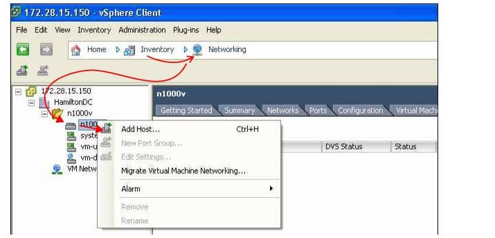
Step 3 ![]() Right-click the switch name, and choose Add Host.
Right-click the switch name, and choose Add Host.
The Add Host to Distributed Virtual Switch Wizard opens.
Note ![]() If the Add Host to Distributed Virtual Switch dialog box is empty, then check to make sure the host has an Enterprise Plus license for VMware ESX 4.0 servers.
If the Add Host to Distributed Virtual Switch dialog box is empty, then check to make sure the host has an Enterprise Plus license for VMware ESX 4.0 servers.
Note ![]() If using VUM, the Cisco Nexus 1000V software is now loaded onto the DVS by VUM.
If using VUM, the Cisco Nexus 1000V software is now loaded onto the DVS by VUM.
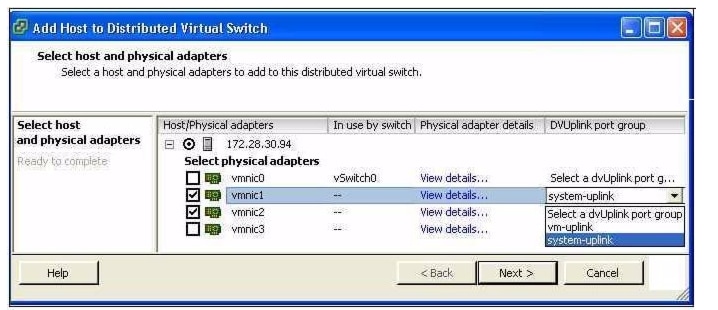
Step 4 ![]() Do one of the following:
Do one of the following:
•![]() If you use the system-uplink profile to carry data traffic and the system-uplink profile has already been defined, then you do not need to assign the vm-uplink profile to another vmnic.
If you use the system-uplink profile to carry data traffic and the system-uplink profile has already been defined, then you do not need to assign the vm-uplink profile to another vmnic.
•![]() If not, click the check box for the next vmnic that is not attached to the VMware vSwitch, for example vmnic1, click the down arrow and then choose the Uplink Port Group system-uplink.
If not, click the check box for the next vmnic that is not attached to the VMware vSwitch, for example vmnic1, click the down arrow and then choose the Uplink Port Group system-uplink.
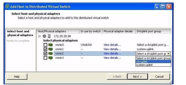
Step 5 ![]() Choose the next vmnic that is not attached to the VMware vSwitch, for example vmnic2.
Choose the next vmnic that is not attached to the VMware vSwitch, for example vmnic2.
It should be linked to the Uplink Port Group vm-uplink.
Note ![]() To add multiple uplinks to the DVS and form a port channel with them, see the Cisco Nexus 1000V Port Profile Configuration Guide, Release 4.2(1)SV1(4).
To add multiple uplinks to the DVS and form a port channel with them, see the Cisco Nexus 1000V Port Profile Configuration Guide, Release 4.2(1)SV1(4).
Step 6 ![]() Click Next.
Click Next.
Step 7 ![]() Verify the port group assignment and click Finish.
Verify the port group assignment and click Finish.
Step 8 ![]() Do one of the following:
Do one of the following:
•![]() If the host is successfully added to the DVS, continue with the next step.
If the host is successfully added to the DVS, continue with the next step.
•![]() If the operation fails, see the Cisco Nexus 1000V Troubleshooting Guide, Release 4.2(1)SV1(4).
If the operation fails, see the Cisco Nexus 1000V Troubleshooting Guide, Release 4.2(1)SV1(4).
Step 9 ![]() You have completed this procedure.
You have completed this procedure.
Return to the CLI Software Configuration Process to continue configuring your VSM.
 Feedback