- Index
- New and Changed Information
- Preface
- Overview
- Configuring FIPS
- Configuring Users and Common Roles
- Configuring RADIUS and TACACS+
- Configuring IPv4 and IPv6 Access Control Lists
- Configuring Certificate Authorities and Digital Certificates
- Configuring IPSec Network Security
- Configuring FC-SP and DHCHAP
- Configuring Port Security
- Configuring Fabric Binding
- Configuring Cisco TrustSec Fibre Channel Link Encryption
- About IPsec
- About IKE
- IPsec Prerequisites
- Using IPsec
- IPsec Digital Certificate Support
- Configuring IPsec Using FCIP Wizard
- Manually Configuring IPsec and IKE
- Optional IKE Parameter Configuration
- Crypto IPv4-ACLs
- About Crypto IPv4-ACLs
- Creating Crypto IPv4-ACLs
- About Transform Sets in IPsec
- Configuring Transform Sets
- About Crypto Map Entries
- Creating Crypto Map Entries
- About SA Lifetime Negotiation
- Setting the SA Lifetime
- About the AutoPeer Option
- Configuring the AutoPeer Option
- About Perfect Forward Secrecy
- Configuring Perfect Forward Secrecy
- About Crypto Map Set Application
- Applying a Crypto Map Set
- IPsec Maintenance
- Global Lifetime Values
- Default Settings
Configuring IPsec Network Security
IP security (IPsec) protocol is a framework of open standards that provides data confidentiality, data integrity, and data authentication between participating peers. It is developed by the Internet Engineering Task Force (IETF). IPsec provides security services at the IP layer, including protecting one or more data flows between a pair of hosts, between a pair of security gateways, or between a security gateway and a host. The overall IPsec implementation is the latest version of RFC 2401. Cisco NX-OS IPsec implements RFC 2402 through RFC 2410.
IPsec uses the Internet Key Exchange (IKE) protocol to handle protocol and algorithm negotiation and to generate the encryption and authentication keys used by IPsec. While IKE can be used with other protocols, its initial implementation is with the IPsec protocol. IKE provides authentication of the IPsec peers, negotiates IPsec security associations, and establishes IPsec keys. IKE uses RFCs 2408, 2409, 2410, and 2412, and additionally implements the draft-ietf-ipsec-ikev2-16.txt draft.

Note ![]() The term IPsec is sometimes used to describe the entire protocol of IPsec data services and IKE security protocols and is other times used to describe only the data services.
The term IPsec is sometimes used to describe the entire protocol of IPsec data services and IKE security protocols and is other times used to describe only the data services.
This chapter includes the following sections:
•![]() IPsec Digital Certificate Support
IPsec Digital Certificate Support
•![]() Configuring IPsec Using FCIP Wizard
Configuring IPsec Using FCIP Wizard
•![]() Manually Configuring IPsec and IKE
Manually Configuring IPsec and IKE
•![]() Optional IKE Parameter Configuration
Optional IKE Parameter Configuration
About IPsec
Note ![]() IPsec is not supported by the Cisco Fabric Switch for HP c-Class BladeSystem and the Cisco Fabric Switch for IBM BladeCenter.
IPsec is not supported by the Cisco Fabric Switch for HP c-Class BladeSystem and the Cisco Fabric Switch for IBM BladeCenter.
IPsec provides security for transmission of sensitive information over unprotected networks such as the Internet. IPsec acts at the network layer, protecting and authenticating IP packets between participating IPsec devices (peers).
IPsec provides the following network security services. In general, the local security policy dictates the use of one or more of these services between two participating IPsec devices:
•![]() Data confidentiality—The IPsec sender can encrypt packets before transmitting them across a network.
Data confidentiality—The IPsec sender can encrypt packets before transmitting them across a network.
•![]() Data integrity—The IPsec receiver can authenticate packets sent by the IPsec sender to ensure that the data has not been altered during transmission.
Data integrity—The IPsec receiver can authenticate packets sent by the IPsec sender to ensure that the data has not been altered during transmission.
•![]() Data origin authentication—The IPsec receiver can authenticate the source of the IPsec packets sent. This service is dependent upon the data integrity service.
Data origin authentication—The IPsec receiver can authenticate the source of the IPsec packets sent. This service is dependent upon the data integrity service.
•![]() Anti-replay protection—The IPsec receiver can detect and reject replayed packets.
Anti-replay protection—The IPsec receiver can detect and reject replayed packets.
Note ![]() The term data authentication is generally used to mean data integrity and data origin authentication. Within this chapter it also includes anti-replay services, unless otherwise specified.
The term data authentication is generally used to mean data integrity and data origin authentication. Within this chapter it also includes anti-replay services, unless otherwise specified.
With IPsec, data can be transmitted across a public network without fear of observation, modification, or spoofing. This enables applications such as Virtual Private Networks (VPNs), including intranets, extranets, and remote user access.
IPsec as implemented in Cisco NX-OS software supports the Encapsulating Security Payload (ESP) protocol. This protocol encapsulates the data to be protected and provides data privacy services, optional data authentication, and optional anti-replay services.
Note ![]() The Encapsulating Security Payload (ESP) protocol is a header inserted into an existing TCP/IP packet, the size of which depends on the actual encryption and authentication algorithms negotiated. To avoid fragmentation, the encrypted packet fits into the interface maximum transmission unit (MTU). The path MTU calculation for TCP takes into account the addition of ESP headers, plus the outer IP header in tunnel mode, for encryption. The MDS switches allow 100 bytes for packet growth for IPsec encryption.
The Encapsulating Security Payload (ESP) protocol is a header inserted into an existing TCP/IP packet, the size of which depends on the actual encryption and authentication algorithms negotiated. To avoid fragmentation, the encrypted packet fits into the interface maximum transmission unit (MTU). The path MTU calculation for TCP takes into account the addition of ESP headers, plus the outer IP header in tunnel mode, for encryption. The MDS switches allow 100 bytes for packet growth for IPsec encryption.
Note ![]() When using IPsec and IKE, each Gigabit Ethernet interface on the IPS module (either on 14+2 LC or 18+4 LC) must be configured in its own IP subnet. If there are multiple Gigabit Ethernet interfaces configured with IP address or network-mask in the same IP subnet, IKE packets may not be sent to the right peer and thus IPsec tunnel will not come up.
When using IPsec and IKE, each Gigabit Ethernet interface on the IPS module (either on 14+2 LC or 18+4 LC) must be configured in its own IP subnet. If there are multiple Gigabit Ethernet interfaces configured with IP address or network-mask in the same IP subnet, IKE packets may not be sent to the right peer and thus IPsec tunnel will not come up.
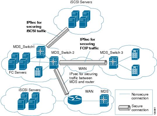
Figure 7-1 shows different IPsec scenarios.
Figure 7-1 FCIP and iSCSI Scenarios Using MPS-14/2 Modules
About IKE
IKE automatically negotiates IPsec security associations and generates keys for all switches using the IPsec feature. Specifically, IKE provides these benefits:
•![]() Allows you to refresh IPsec SAs.
Allows you to refresh IPsec SAs.
•![]() Allows IPsec to provide anti-replay services.
Allows IPsec to provide anti-replay services.
•![]() Supports a manageable, scalable IPsec configuration.
Supports a manageable, scalable IPsec configuration.
•![]() Allows dynamic authentication of peers.
Allows dynamic authentication of peers.
Note ![]() IKE is not supported on the Cisco Fabric Switch for HP c-Class BladeSystem and the Cisco Fabric Switch for IBM BladeSystem.
IKE is not supported on the Cisco Fabric Switch for HP c-Class BladeSystem and the Cisco Fabric Switch for IBM BladeSystem.
IPsec Prerequisites
To use the IPsec feature, you need to perform the following tasks:
•![]() Obtain the ENTERPRISE_PKG license (see the Cisco MDS 9000 Family NX-OS Licensing Guide).
Obtain the ENTERPRISE_PKG license (see the Cisco MDS 9000 Family NX-OS Licensing Guide).
•![]() Configure IKE as described in the "About IKE Initialization" section.
Configure IKE as described in the "About IKE Initialization" section.
Using IPsec
To use the IPsec feature, follow these steps:
Step 1 ![]() Obtain the ENTERPRISE_PKG license to enable IPsec for iSCSI and to enable IPsec for FCIP. See the Cisco MDS 9000 Family NX-OS Licensing Guide for more information.
Obtain the ENTERPRISE_PKG license to enable IPsec for iSCSI and to enable IPsec for FCIP. See the Cisco MDS 9000 Family NX-OS Licensing Guide for more information.
Step 2 ![]() Configure IKE as described in the "Manually Configuring IPsec and IKE" section.
Configure IKE as described in the "Manually Configuring IPsec and IKE" section.
Note ![]() The IPsec feature inserts new headers in existing packets (see the Cisco Fabric Manager IP Services Configuration Guidefor more information).
The IPsec feature inserts new headers in existing packets (see the Cisco Fabric Manager IP Services Configuration Guidefor more information).
This section contains the following topics:
•![]() Supported IPsec Transforms and Algorithms
Supported IPsec Transforms and Algorithms
•![]() Supported IKE Transforms and Algorithms
Supported IKE Transforms and Algorithms
IPsec Compatibility
IPsec features are compatible with the following Cisco MDS 9000 Family hardware:
•![]() Cisco 18/4-port Multi-Service Module (MSM-18/4) modules and MDS 9222i Module-1 modules.
Cisco 18/4-port Multi-Service Module (MSM-18/4) modules and MDS 9222i Module-1 modules.
•![]() Cisco 14/2-port Multiprotocol Services (MPS-14/2) modules in Cisco MDS 9200 Switches or Cisco MDS 9500 Directors
Cisco 14/2-port Multiprotocol Services (MPS-14/2) modules in Cisco MDS 9200 Switches or Cisco MDS 9500 Directors
•![]() Cisco MDS 9216i Switch with the 14/2-port multiprotocol capability in the integrated supervisor module. Refer to the Cisco MDS 9200 Series Hardware Installation Guide for more information on the Cisco MDS 9216i Switch.
Cisco MDS 9216i Switch with the 14/2-port multiprotocol capability in the integrated supervisor module. Refer to the Cisco MDS 9200 Series Hardware Installation Guide for more information on the Cisco MDS 9216i Switch.
•![]() The IPsec feature is not supported on the management interface.
The IPsec feature is not supported on the management interface.
IPsec features are compatible with the following fabric setup:
•![]() Two connected Cisco MDS 9200 Switches or Cisco MDS 9500 Directors running Cisco MDS SAN-OS Release 2.0(1b) or later, or Cisco NX-OS 4.1(1).
Two connected Cisco MDS 9200 Switches or Cisco MDS 9500 Directors running Cisco MDS SAN-OS Release 2.0(1b) or later, or Cisco NX-OS 4.1(1).
•![]() A Cisco MDS 9200 Switches or Cisco MDS 9500 Directors running Cisco MDS SAN-OS Release 2.0(1b) or later, or Cisco NX-OS 4.1(1) connected to any IPsec compliant device.
A Cisco MDS 9200 Switches or Cisco MDS 9500 Directors running Cisco MDS SAN-OS Release 2.0(1b) or later, or Cisco NX-OS 4.1(1) connected to any IPsec compliant device.
•![]() The following features are not supported in the Cisco NX-OS implementation of the IPsec feature:
The following features are not supported in the Cisco NX-OS implementation of the IPsec feature:
–![]() Authentication Header (AH).
Authentication Header (AH).
–![]() Transport mode.
Transport mode.
–![]() Security association bundling.
Security association bundling.
–![]() Manually configuring security associations.
Manually configuring security associations.
–![]() Per host security association option in a crypto map.
Per host security association option in a crypto map.
–![]() Security association idle timeout
Security association idle timeout
–![]() Dynamic crypto maps.
Dynamic crypto maps.
Note ![]() Any reference to crypto maps in this document, only refers to static crypto maps.
Any reference to crypto maps in this document, only refers to static crypto maps.
IPsec and IKE Terminology
The terms used in this chapter are explained in this section.
•![]() Security association (SA)— An agreement between two participating peers on the entries required to encrypt and decrypt IP packets. Two SAs are required for each peer in each direction (inbound and outbound) to establish bidirectional communication between the peers. Sets of bidirectional SA records are stored in the SA database (SAD). IPsec uses IKE to negotiate and bring up SAs. Each SA record includes the following information:
Security association (SA)— An agreement between two participating peers on the entries required to encrypt and decrypt IP packets. Two SAs are required for each peer in each direction (inbound and outbound) to establish bidirectional communication between the peers. Sets of bidirectional SA records are stored in the SA database (SAD). IPsec uses IKE to negotiate and bring up SAs. Each SA record includes the following information:
–![]() Security parameter index (SPI)—A number which, together with a destination IP address and security protocol, uniquely identifies a particular SA. When using IKE to establish the SAs, the SPI for each SA is a pseudo-randomly derived number.
Security parameter index (SPI)—A number which, together with a destination IP address and security protocol, uniquely identifies a particular SA. When using IKE to establish the SAs, the SPI for each SA is a pseudo-randomly derived number.
–![]() Peer—A switch or other device that participates in IPsec. For example, a Cisco MDS switch or other Cisco routers that support IPsec.
Peer—A switch or other device that participates in IPsec. For example, a Cisco MDS switch or other Cisco routers that support IPsec.
–![]() Transform—A list of operations done to provide data authentication and data confidentiality. For example, one transform is the ESP protocol with the HMAC-MD5 authentication algorithm.
Transform—A list of operations done to provide data authentication and data confidentiality. For example, one transform is the ESP protocol with the HMAC-MD5 authentication algorithm.
–![]() Session key—The key used by the transform to provide security services.
Session key—The key used by the transform to provide security services.
–![]() Lifetime—A lifetime counter (in seconds and bytes) is maintained from the time the SA is created. When the time limit expires the SA is no longer operational and, if required, is automatically renegotiated (rekeyed).
Lifetime—A lifetime counter (in seconds and bytes) is maintained from the time the SA is created. When the time limit expires the SA is no longer operational and, if required, is automatically renegotiated (rekeyed).
–![]() Mode of operation—Two modes of operation are generally available for IPsec: tunnel mode and transport mode. The Cisco NX-OS implementation of IPsec only supports the tunnel mode. The IPsec tunnel mode encrypts and authenticates the IP packet, including its header. The gateways encrypt traffic on behalf of the hosts and subnets.
Mode of operation—Two modes of operation are generally available for IPsec: tunnel mode and transport mode. The Cisco NX-OS implementation of IPsec only supports the tunnel mode. The IPsec tunnel mode encrypts and authenticates the IP packet, including its header. The gateways encrypt traffic on behalf of the hosts and subnets.
The Cisco NX-OS implementation of IPsec does not support transport mode.
Note ![]() The term tunnel mode is different from the term tunnel, which is used to indicate a secure communication path between two peers, such as two switches connected by an FCIP link.
The term tunnel mode is different from the term tunnel, which is used to indicate a secure communication path between two peers, such as two switches connected by an FCIP link.
•![]() Anti-replay—A security service where the receiver can reject old or duplicate packets to protect itself against replay attacks. IPsec provides this optional service by use of a sequence number combined with the use of data authentication.
Anti-replay—A security service where the receiver can reject old or duplicate packets to protect itself against replay attacks. IPsec provides this optional service by use of a sequence number combined with the use of data authentication.
•![]() Data authentication—Data authentication can refer either to integrity alone or to both integrity and authentication (data origin authentication is dependent on data integrity).
Data authentication—Data authentication can refer either to integrity alone or to both integrity and authentication (data origin authentication is dependent on data integrity).
–![]() Data integrity—Verifies that data has not been altered.
Data integrity—Verifies that data has not been altered.
–![]() Data origin authentication—Verifies that the data was actually sent by the claimed sender.
Data origin authentication—Verifies that the data was actually sent by the claimed sender.
•![]() Data confidentiality—A security service where the protected data cannot be observed.
Data confidentiality—A security service where the protected data cannot be observed.
•![]() Data flow—A grouping of traffic, identified by a combination of source address and mask or prefix, destination address mask or prefix length, IP next protocol field, and source and destination ports, where the protocol and port fields can have any of these values. Traffic matching a specific combination of these values is logically grouped together into a data flow. A data flow can represent a single TCP connection between two hosts, or it can represent traffic between two subnets. IPsec protection is applied to data flows.
Data flow—A grouping of traffic, identified by a combination of source address and mask or prefix, destination address mask or prefix length, IP next protocol field, and source and destination ports, where the protocol and port fields can have any of these values. Traffic matching a specific combination of these values is logically grouped together into a data flow. A data flow can represent a single TCP connection between two hosts, or it can represent traffic between two subnets. IPsec protection is applied to data flows.
•![]() Perfect forward secrecy (PFS)—A cryptographic characteristic associated with a derived shared secret value. With PFS, if one key is compromised, previous and subsequent keys are not compromised, because subsequent keys are not derived from previous keys.
Perfect forward secrecy (PFS)—A cryptographic characteristic associated with a derived shared secret value. With PFS, if one key is compromised, previous and subsequent keys are not compromised, because subsequent keys are not derived from previous keys.
•![]() Security Policy Database (SPD)—An ordered list of policies applied to traffic. A policy decides if a packet requires IPsec processing, if it should be allowed in clear text, or if it should be dropped.
Security Policy Database (SPD)—An ordered list of policies applied to traffic. A policy decides if a packet requires IPsec processing, if it should be allowed in clear text, or if it should be dropped.
–![]() The IPsec SPDs are derived from user configuration of crypto maps.
The IPsec SPDs are derived from user configuration of crypto maps.
–![]() The IKE SPD is configured by the user.
The IKE SPD is configured by the user.
Supported IPsec Transforms and Algorithms
The component technologies implemented for IPsec include the following transforms:
•![]() Advanced Encrypted Standard (AES) is an encryption algorithm. It implements either 128 or 256 bits using Cipher Block Chaining (CBC) or counter mode.
Advanced Encrypted Standard (AES) is an encryption algorithm. It implements either 128 or 256 bits using Cipher Block Chaining (CBC) or counter mode.
•![]() Data Encryption Standard (DES) is used to encrypt packet data and implements the mandatory 56-bit DES-CBC. CBC requires an initialization vector (IV) to start encryption. The IV is explicitly given in the IPsec packet.
Data Encryption Standard (DES) is used to encrypt packet data and implements the mandatory 56-bit DES-CBC. CBC requires an initialization vector (IV) to start encryption. The IV is explicitly given in the IPsec packet.
•![]() Triple DES (3DES) is a stronger form of DES with 168-bit encryption keys that allow sensitive information to be transmitted over untrusted networks.
Triple DES (3DES) is a stronger form of DES with 168-bit encryption keys that allow sensitive information to be transmitted over untrusted networks.
Note ![]() Cisco NX-OS images with strong encryption are subject to United States government export controls, and have a limited distribution. Images to be installed outside the United States require an export license. Customer orders might be denied or subject to delay due to United States government regulations. Contact your sales representative or distributor for more information, or send e-mail to export@cisco.com.
Cisco NX-OS images with strong encryption are subject to United States government export controls, and have a limited distribution. Images to be installed outside the United States require an export license. Customer orders might be denied or subject to delay due to United States government regulations. Contact your sales representative or distributor for more information, or send e-mail to export@cisco.com.
•![]() Message Digest 5 (MD5) is a hash algorithm with the HMAC variant. HMAC is a keyed hash variant used to authenticate data.
Message Digest 5 (MD5) is a hash algorithm with the HMAC variant. HMAC is a keyed hash variant used to authenticate data.
•![]() Secure Hash Algorithm (SHA-1) is a hash algorithm with the Hash Message Authentication Code (HMAC) variant.
Secure Hash Algorithm (SHA-1) is a hash algorithm with the Hash Message Authentication Code (HMAC) variant.
•![]() AES-XCBC-MAC is a Message Authentication Code (MAC) using the AES algorithm.
AES-XCBC-MAC is a Message Authentication Code (MAC) using the AES algorithm.
Supported IKE Transforms and Algorithms
The component technologies implemented for IKE include the following transforms:
•![]() Diffie-Hellman (DH) is a public-key cryptography protocol that allows two parties to establish a shared secret over an unsecure communications channel. Diffie-Hellman is used within IKE to establish session keys. Group 1 (768-bit), Group 2 (1024-bit), and Group 5 (1536-bit) are supported.
Diffie-Hellman (DH) is a public-key cryptography protocol that allows two parties to establish a shared secret over an unsecure communications channel. Diffie-Hellman is used within IKE to establish session keys. Group 1 (768-bit), Group 2 (1024-bit), and Group 5 (1536-bit) are supported.
•![]() Advanced Encrypted Standard (AES) is an encryption algorithm. It implements either 128 bits using Cipher Block Chaining (CBC) or counter mode.
Advanced Encrypted Standard (AES) is an encryption algorithm. It implements either 128 bits using Cipher Block Chaining (CBC) or counter mode.
•![]() Data Encryption Standard (DES) is used to encrypt packet data and implements the mandatory 56-bit DES-CBC. CBC requires an initialization vector (IV) to start encryption. The IV is explicitly given in the IPsec packet.
Data Encryption Standard (DES) is used to encrypt packet data and implements the mandatory 56-bit DES-CBC. CBC requires an initialization vector (IV) to start encryption. The IV is explicitly given in the IPsec packet.
•![]() Triple DES (3DES) is a stronger form of DES with 168-bit encryption keys that allow sensitive information to be transmitted over untrusted networks.
Triple DES (3DES) is a stronger form of DES with 168-bit encryption keys that allow sensitive information to be transmitted over untrusted networks.
Note ![]() Cisco NX-OS images with strong encryption are subject to United States government export controls, and have a limited distribution. Images to be installed outside the United States require an export license. Customer orders might be denied or subject to delay due to United States government regulations. Contact your sales representative or distributor for more information, or send e-mail to export@cisco.com.
Cisco NX-OS images with strong encryption are subject to United States government export controls, and have a limited distribution. Images to be installed outside the United States require an export license. Customer orders might be denied or subject to delay due to United States government regulations. Contact your sales representative or distributor for more information, or send e-mail to export@cisco.com.
•![]() Message Digest 5 (MD5) is a hash algorithm with the HMAC variant. HMAC is a keyed hash variant used to authenticate data.
Message Digest 5 (MD5) is a hash algorithm with the HMAC variant. HMAC is a keyed hash variant used to authenticate data.
•![]() Secure Hash Algorithm (SHA-1) is a hash algorithm with the Hash Message Authentication Code (HMAC) variant.
Secure Hash Algorithm (SHA-1) is a hash algorithm with the Hash Message Authentication Code (HMAC) variant.
•![]() The switch authentication algorithm uses the preshared keys based on the IP address
The switch authentication algorithm uses the preshared keys based on the IP address
IPsec Digital Certificate Support
This section describes the advantages of using certificate authorities (CAs) and digital certificates for authentication.
Implementing IPsec Without CAs and Digital Certificates
Without a CA and digital certificates, enabling IPsec services (such as encryption) between two Cisco MDS switches requires that each switch has the key of the other switch (such as an RSA public key or a shared key). You must manually specify either the RSA public keys or preshared keys on each switch in the fabric using IPsec services. Also, each new device added to the fabric will require manual configuration of the other switches in the fabric to support secure communication.
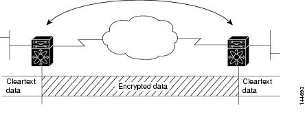
In Figure 7-2, each switch uses the key of the other switch to authenticate the identity of the other switch; this authentication always occurs when IPsec traffic is exchanged between the two switches.
If you have multiple Cisco MDS switches in a mesh topology and wish to exchange IPsec traffic passing among all of those switches, you must first configure shared keys or RSA public keys among all of those switches.
Figure 7-2 Two IPsec Switches Without CAs and Digital Certificates
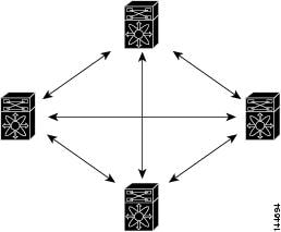
Every time a new switch is added to the IPsec network, you must configure keys between the new switch and each of the existing switches. (In Figure 7-3, four additional two-part key configurations are required to add a single encrypting switch to the network).
Consequently, the more devices that require IPsec services, the more involved the key administration becomes. This approach does not scale well for larger, more complex encrypting networks.
Figure 7-3 Four IPsec Switches Without a CA and Digital Certificates
Implementing IPsec with CAs and Digital Certificates
With CA and digital certificates, you do not have to configure keys between all the encrypting switches. Instead, you individually enroll each participating switch with the CA, requesting a certificate for the switch. When this has been accomplished, each participating switch can dynamically authenticate all the other participating switches. When two devices want to communicate, they exchange certificates and digitally sign data to authenticate each other. When a new device is added to the network, you simply enroll that device with a CA, and none of the other devices needs modification. When the new device attempts an IPsec connection, certificates are automatically exchanged and the device can be authenticated.
Figure 7-4 shows the process of dynamically authenticating the devices.
Figure 7-4 Dynamically Authenticating Devices with a CA
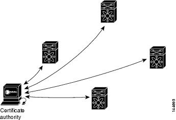
To add a new IPsec switch to the network, you need only configure that new switch to request a certificate from the CA, instead of making multiple key configurations with all the other existing IPsec switches.
How CA Certificates Are Used by IPsec Devices
When two IPsec switches want to exchange IPsec-protected traffic passing between them, they must first authenticate each other—otherwise, IPsec protection cannot occur. The authentication is done with IKE.
IKE can use two methods to authenticate the switches, using preshared keys without a CA and using RSA key-pairs with a CA. Both methods require that keys must be preconfigured between the two switches.
Without a CA, a switch authenticates itself to the remote switch using either RSA-encrypted preshared keys.
With a CA, a switch authenticates itself to the remote switch by sending a certificate to the remote switch and performing some public key cryptography. Each switch must send its own unique certificate that was issued and validated by the CA. This process works because the certificate of each switch encapsulates the public key of the switch, each certificate is authenticated by the CA, and all participating switches recognize the CA as an authenticating authority. This scheme is called IKE with an RSA signature.
Your switch can continue sending its own certificate for multiple IPsec sessions, and to multiple IPsec peers until the certificate expires. When the certificate expires, the switch administrator must obtain a new one from the CA.
CAs can also revoke certificates for devices that will no longer participate in IPsec. Revoked certificates are not recognized as valid by other IPsec devices. Revoked certificates are listed in a certificate revocation list (CRL), which each peer may check before accepting a certificate from another peer.
Certificate support for IKE has the following considerations:
•![]() The switch FQDN (host name and domain name) must be configured before installing certificates for IKE.
The switch FQDN (host name and domain name) must be configured before installing certificates for IKE.
•![]() Only those certificates that are configured for IKE or general usage are used by IKE.
Only those certificates that are configured for IKE or general usage are used by IKE.
•![]() The first IKE or general usage certificate configured on the switch is used as the default certificate by IKE.
The first IKE or general usage certificate configured on the switch is used as the default certificate by IKE.
•![]() The default certificate is for all IKE peers unless the peer specifies another certificate.
The default certificate is for all IKE peers unless the peer specifies another certificate.
•![]() If the peer asks for a certificate which is signed by a CA that it trusts, then IKE uses that certificate, if it exists on the switch, even if it is not the default certificate.
If the peer asks for a certificate which is signed by a CA that it trusts, then IKE uses that certificate, if it exists on the switch, even if it is not the default certificate.
•![]() If the default certificate is deleted, the next IKE or general usage certificate, if any exists, is used by IKE as the default certificate.
If the default certificate is deleted, the next IKE or general usage certificate, if any exists, is used by IKE as the default certificate.
•![]() Certificate chaining is not supported by IKE.
Certificate chaining is not supported by IKE.
•![]() IKE only sends the identity certificate, not the entire CA chain. For the certificate to be verified on the peer, the same CA chain must also exist there.
IKE only sends the identity certificate, not the entire CA chain. For the certificate to be verified on the peer, the same CA chain must also exist there.
Configuring IPsec Using FCIP Wizard
Fabric Manager simplifies the configuration of IPsec and IKE by enabling and configuring these features as part of the FCIP configuration using the FCIP Wizard.
To enable IPsec using the FCIP Wizard in Fabric Manager, follow these steps:
Step 1 ![]() Click the FCIP Wizard icon in the toolbar.
Click the FCIP Wizard icon in the toolbar.
Figure 7-5 FCIP Wizard
Step 2 ![]() Choose the switches that act as end points for the FCIP link and click Next.
Choose the switches that act as end points for the FCIP link and click Next.
Note ![]() These switches must have MPS-14/2 modules installed to configure IPsec on this FCIP link.
These switches must have MPS-14/2 modules installed to configure IPsec on this FCIP link.
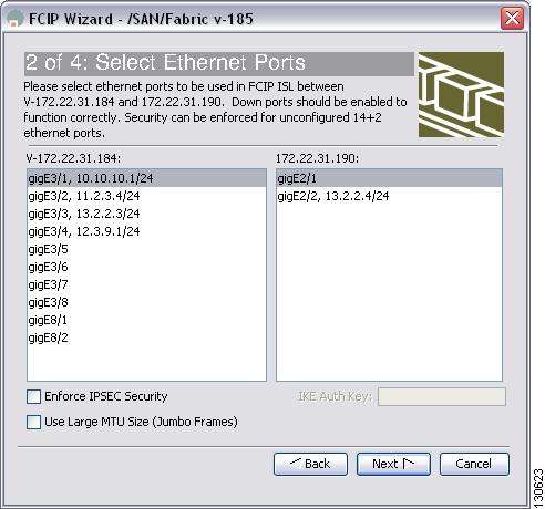
Step 3 ![]() Choose the Gigabit Ethernet ports on each MPS-14/2 module that will form the FCIP link.
Choose the Gigabit Ethernet ports on each MPS-14/2 module that will form the FCIP link.
Step 4 ![]() Check the Enforce IPSEC Security check box and set IKE Auth Key (see Figure 7-6).
Check the Enforce IPSEC Security check box and set IKE Auth Key (see Figure 7-6).
Figure 7-6 Enabling IPsec on an FCIP Link
Step 5 ![]() Click Next. In the Specify Tunnel Properties dialog box, you see the TCP connection characteristics.
Click Next. In the Specify Tunnel Properties dialog box, you see the TCP connection characteristics.
Step 6 ![]() Set the minimum and maximum bandwidth settings and round-trip time for the TCP connections on this FCIP link. Click the Measure button to measure the round-trip time between the Gigabit Ethernet endpoints.
Set the minimum and maximum bandwidth settings and round-trip time for the TCP connections on this FCIP link. Click the Measure button to measure the round-trip time between the Gigabit Ethernet endpoints.
Step 7 ![]() Check the Enable Write Acceleration check box to enable FCIP write acceleration on this FCIP link.
Check the Enable Write Acceleration check box to enable FCIP write acceleration on this FCIP link.
Step 8 ![]() Check the Enable Optimum Compression check box to enable IP compression on this FCIP link.
Check the Enable Optimum Compression check box to enable IP compression on this FCIP link.
Step 9 ![]() Click Next to configure the FCIP tunnel parameters.
Click Next to configure the FCIP tunnel parameters.
Step 10 ![]() Set the Port VSAN for nontrunk/auto and allowed VSAN list for the trunk tunnel. choose a Trunk Mode for this FCIP link. See Cisco Fabric Manager IP Services Configuration Guide.
Set the Port VSAN for nontrunk/auto and allowed VSAN list for the trunk tunnel. choose a Trunk Mode for this FCIP link. See Cisco Fabric Manager IP Services Configuration Guide.
Step 11 ![]() Click Finish to create this FCIP link or click Cancel to exit the FCIP Wizard without creating an FCIP link.
Click Finish to create this FCIP link or click Cancel to exit the FCIP Wizard without creating an FCIP link.
To verify that IPsec and IKE are enabled using Fabric Manager, follow these steps:
Step 1 ![]() Expand Switches > Security and then select IPSEC in the Physical Attributes pane.
Expand Switches > Security and then select IPSEC in the Physical Attributes pane.
You see the IPsec configuration in the Information pane in Figure 7-7.
Figure 7-7 IPSec Configuration
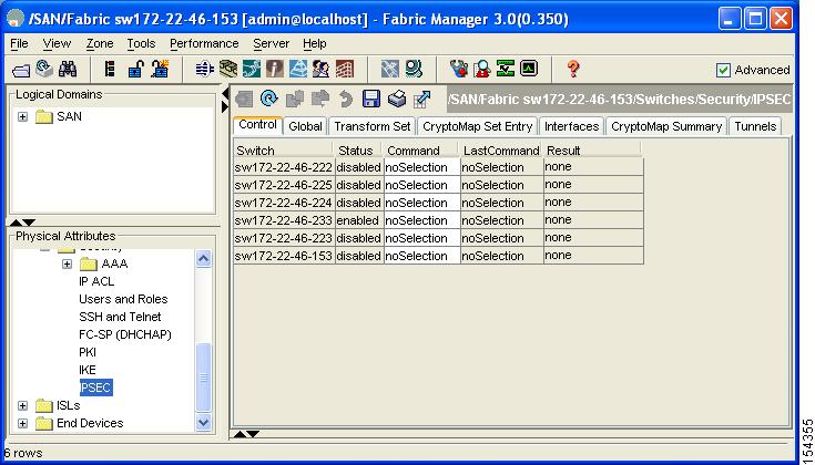
Step 2 ![]() The Control tab is the default. Verify that the switches you want to modify for IPSec are enabled in the Status column.
The Control tab is the default. Verify that the switches you want to modify for IPSec are enabled in the Status column.
Step 3 ![]() Expand Switches > Security and then select IKE in the Physical Attributes pane.
Expand Switches > Security and then select IKE in the Physical Attributes pane.
You see the IKE configuration in the Information pane shown in Figure 7-8.
Figure 7-8 IKE Configuration
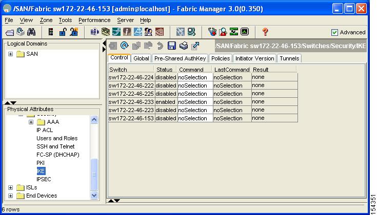
Step 4 ![]() The Control tab is the default. Verify that the switches you want to modify for IKE are enabled in the Status column.
The Control tab is the default. Verify that the switches you want to modify for IKE are enabled in the Status column.
Manually Configuring IPsec and IKE
This section describes how to manually configure IPsec and IKE if you are not using the FCIP Wizard. See "Configuring IPsec Using FCIP Wizard" section.
IPsec provides secure data flows between participating peers. Multiple IPsec data flows can exist between two peers to secure different data flows, with each tunnel using a separate set of SAs.
After you have completed IKE configuration, configure IPsec.
To configure IPsec in each participating IPsec peer, follow these steps:
Step 1 ![]() Identify the peers for the traffic to which secure tunnels should be established.
Identify the peers for the traffic to which secure tunnels should be established.
Step 2 ![]() Configure the transform set with the required protocols and algorithms.
Configure the transform set with the required protocols and algorithms.
Step 3 ![]() Create the crypto map and apply access control lists (IPv4-ACLs), transform sets, peers, and lifetime values as applicable.
Create the crypto map and apply access control lists (IPv4-ACLs), transform sets, peers, and lifetime values as applicable.
Step 4 ![]() Apply the crypto map to the required interface.
Apply the crypto map to the required interface.
This section contains the following topics:
About IKE Initialization
The IKE feature must first be enabled and configured so the IPsec feature can establish data flow with the required peer. Fabric Manager initializes IKE when you first configure it.
You cannot disable IKE if IPsec is enabled. If you disable the IKE feature, the IKE configuration is cleared from the running configuration.
About the IKE Domain
You must apply the IKE configuration to an IPsec domain to allow traffic to reach the supervisor module in the local switch. Fabric Manager sets the IPsec domain automatically when you configure IKE.
About IKE Tunnels
An IKE tunnel is a secure IKE session between two endpoints. IKE creates this tunnel to protect IKE messages used in IPsec SA negotiations.
Two versions of IKE are used in the Cisco NX-OS implementation.
•![]() IKE version 1 (IKEv1) is implemented using RFC 2407, 2408, 2409, and 2412.
IKE version 1 (IKEv1) is implemented using RFC 2407, 2408, 2409, and 2412.
•![]() IKE version 2 (IKEv2) is a simplified and more efficient version and does not interoperate with IKEv1. IKEv2 is implemented using the draft-ietf-ipsec-ikev2-16.txt draft.
IKE version 2 (IKEv2) is a simplified and more efficient version and does not interoperate with IKEv1. IKEv2 is implemented using the draft-ietf-ipsec-ikev2-16.txt draft.
About IKE Policy Negotiation
To protect IKE negotiations, each IKE negotiation begins with a common (shared) IKE policy. An IKE policy defines a combination of security parameters to be used during the IKE negotiation. By default, no IKE policy is configured. You must create IKE policies at each peer. This policy states which security parameters will be used to protect subsequent IKE negotiations and mandates how peers are authenticated. You can create multiple, prioritized policies at each peer to ensure that at least one policy will match a remote peer's policy.
You can configure the policy based on the encryption algorithm (DES, 3DES, or AES), the hash algorithm (SHA or MD5), and the DH group (1, 2, or 5). Each policy can contain a different combination of parameter values. A unique priority number identifies the configured policy. This number ranges from 1 (highest priority) to 255 (lowest priority). You can create multiple policies in a switch. If you need to connect to a remote peer, you must ascertain that at least one policy in the local switch contains the identical parameter values configured in the remote peer. If several policies have identical parameter configurations, the policy with the lowest number is selected.
Table 7-1 provides a list of allowed transform combinations.
The following table lists the supported and verified settings for IPsec and IKE encryption authentication algorithms on the Microsoft Windows and Linux platforms:
Note ![]() When you configure the hash algorithm, the corresponding HMAC version is used as the authentication algorithm.
When you configure the hash algorithm, the corresponding HMAC version is used as the authentication algorithm.
When the IKE negotiation begins, IKE looks for an IKE policy that is the same on both peers. The peer that initiates the negotiation will send all its policies to the remote peer, and the remote peer will try to find a match. The remote peer looks for a match by comparing its own highest priority policy against the other peer's received policies. The remote peer checks each of its policies in order of its priority (highest priority first) until a match is found.
A match is found when the two peers have the same encryption, hash algorithm, authentication algorithm, and DH group values. If a match is found, IKE completes the security negotiation and the IPsec SAs are created.
If an acceptable match is not found, IKE refuses negotiation and the IPsec data flows will not be established.
Configuring an IKE Policy
To configure the IKE policy negotiation parameters using Fabric Manager, follow these steps:
Step 1 ![]() Expand Switches > Security and then select IKE.
Expand Switches > Security and then select IKE.
You see the IKE configuration in the Information pane in Figure 7-9.
Figure 7-9 IKE Configuration
Step 2 ![]() Click the Policies tab.
Click the Policies tab.
You see the existing IKE polices in the Information pane.
Step 3 ![]() Click Create Row to create an IKE policy.
Click Create Row to create an IKE policy.
You see the Create Policy dialog box shown in Figure 7-10.
Figure 7-10 Create IKE
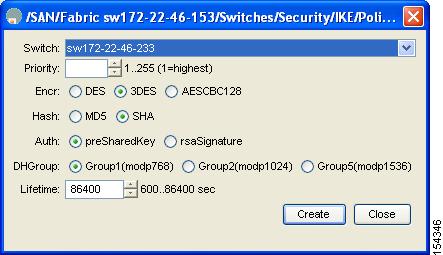
Step 4 ![]() Enter the Priority for this switch. You can enter a value from one through 255, one being the highest.
Enter the Priority for this switch. You can enter a value from one through 255, one being the highest.
Step 5 ![]() Select appropriate values for the encryption, hash, authentication, and DHGroup fields.
Select appropriate values for the encryption, hash, authentication, and DHGroup fields.
Step 6 ![]() Enter the lifetime for the policy. You can enter a lifetime from 600 to 86400 seconds.
Enter the lifetime for the policy. You can enter a lifetime from 600 to 86400 seconds.
Step 7 ![]() Click Create to create this policy, or click Close to discard any unsaved changes.
Click Create to create this policy, or click Close to discard any unsaved changes.
Note ![]() When the authentication method is rsa-sig, make sure the identity hostname is configured for IKE because the IKE certificate has a subject name of the FQDN type.
When the authentication method is rsa-sig, make sure the identity hostname is configured for IKE because the IKE certificate has a subject name of the FQDN type.
Optional IKE Parameter Configuration
You can optionally configure the following parameters for the IKE feature:
•![]() The lifetime association within each policy—The lifetime ranges from 600 to 86,400 seconds. The default is 86,400 seconds (equals one day). The lifetime association within each policy is configured when you are creating an IKE policy. See the "Configuring an IKE Policy" section.
The lifetime association within each policy—The lifetime ranges from 600 to 86,400 seconds. The default is 86,400 seconds (equals one day). The lifetime association within each policy is configured when you are creating an IKE policy. See the "Configuring an IKE Policy" section.
•![]() The keepalive time for each peer if you use IKEv2—The keepalive ranges from 120 to 86,400 seconds. The default is 3,600 seconds (equals one hour).
The keepalive time for each peer if you use IKEv2—The keepalive ranges from 120 to 86,400 seconds. The default is 3,600 seconds (equals one hour).
•![]() The initiator version for each peer—IKE v1 or IKE v2 (default). Your choice of initiator version does not affect interoperability when the remote device initiates the negotiation. Configure this option if the peer device supports IKEv1 and you can play the initiator role for IKE with the specified device. Use the following considerations when configuring the initiator version with FCIP tunnels:
The initiator version for each peer—IKE v1 or IKE v2 (default). Your choice of initiator version does not affect interoperability when the remote device initiates the negotiation. Configure this option if the peer device supports IKEv1 and you can play the initiator role for IKE with the specified device. Use the following considerations when configuring the initiator version with FCIP tunnels:
–![]() If the switches on both sides of an FCIP tunnel are running MDS SAN-OS Release 3.0(1) or later, or Cisco NX-OS 4.1(1) you must configure initiator version IKEv1 on both sides of an FCIP tunnel to use only IKEv1. If one side of an FCIP tunnel is using IKEv1 and the other side is using IKEv2, the FCIP tunnel uses IKEv2.
If the switches on both sides of an FCIP tunnel are running MDS SAN-OS Release 3.0(1) or later, or Cisco NX-OS 4.1(1) you must configure initiator version IKEv1 on both sides of an FCIP tunnel to use only IKEv1. If one side of an FCIP tunnel is using IKEv1 and the other side is using IKEv2, the FCIP tunnel uses IKEv2.
–![]() If the switch on one side of an FCIP tunnel is running MDS SAN-OS Release 3.0(1) or later, or Cisco NX-OS 4.1(1b) and the switch on the other side of the FCIP tunnel is running MDS SAN-OS Release 2.x, configuring IKEv1 on either side (or both) results in the FCIP tunnel using IKEv1.
If the switch on one side of an FCIP tunnel is running MDS SAN-OS Release 3.0(1) or later, or Cisco NX-OS 4.1(1b) and the switch on the other side of the FCIP tunnel is running MDS SAN-OS Release 2.x, configuring IKEv1 on either side (or both) results in the FCIP tunnel using IKEv1.
Note ![]() Only IKE v1 is supported to build IPsec between 2.x and 3.x MDS switches.
Only IKE v1 is supported to build IPsec between 2.x and 3.x MDS switches.

Caution

Tip ![]() The keepalive time only applies to IKEv2 peers and not to all peers.
The keepalive time only applies to IKEv2 peers and not to all peers.
Note ![]() When IPsec implementations in the host prefer to initiate the IPsec rekey, be sure to configure the IPsec lifetime value in the Cisco MDS switch to be higher than the lifetime value in the host.
When IPsec implementations in the host prefer to initiate the IPsec rekey, be sure to configure the IPsec lifetime value in the Cisco MDS switch to be higher than the lifetime value in the host.
This section includes the following topics:
•![]() Configuring the Keepalive Time for a Peer
Configuring the Keepalive Time for a Peer
•![]() Configuring the Initiator Version
Configuring the Initiator Version
•![]() Clearing IKE Tunnels or Domains
Clearing IKE Tunnels or Domains
Configuring the Keepalive Time for a Peer
To configure the keepalive time for each peer using Fabric Manager, follow these steps:
Step 1 ![]() Expand Switches > Security and then select IKE.
Expand Switches > Security and then select IKE.
You see the IKE configuration in the Information pane (see Figure 7-11).
Figure 7-11 IKE Configuration
Step 2 ![]() Select the Global tab.
Select the Global tab.
You see the global statistics of a specific IKE protocol in the Information pane (see Figure 7-12).
Figure 7-12 IKE Global Tab Information
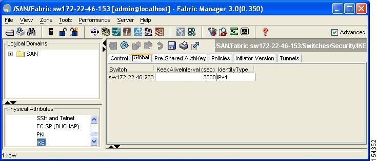
Step 3 ![]() Enter a value (in seconds) in the KeepAliveInterval (sec). The keepalive interval in seconds is used by the IKE entity on the managed device with all the peers for the DOI corresponding to this conceptual row.
Enter a value (in seconds) in the KeepAliveInterval (sec). The keepalive interval in seconds is used by the IKE entity on the managed device with all the peers for the DOI corresponding to this conceptual row.
Step 4 ![]() Click Apply Changes to save your changes.
Click Apply Changes to save your changes.
Configuring the Initiator Version
To configure the initiator version using Fabric Manager, follow these steps:
Step 1 ![]() Expand Switches > Security and then select IKE.
Expand Switches > Security and then select IKE.
You see the IKE configuration in the Information pane (see Figure 7-13).
Figure 7-13 IKE Configuration
Step 2 ![]() Select the Initiator Version tab.
Select the Initiator Version tab.
You see the existing initiator versions for the peers in the Information pane.
Step 3 ![]() Click Create Row to create an initiator version.
Click Create Row to create an initiator version.
You see the Create Initiator Version dialog box shown in Figure 7-14.
Figure 7-14 Create Initiator Version Dialog Box
Step 4 ![]() Select the Switches for the remote peer for which this IKE protocol initiator is configured.
Select the Switches for the remote peer for which this IKE protocol initiator is configured.
Step 5 ![]() Enter the IP address of the remote peer.
Enter the IP address of the remote peer.
IKEv1 represents the IKE protocol version used when connecting to a remote peer.
Step 6 ![]() Click Create to create this initiator version or click Close to discard any unsaved changes.
Click Create to create this initiator version or click Close to discard any unsaved changes.
Clearing IKE Tunnels or Domains
If an IKE tunnel ID is not specified for the IKE configuration, you can clear all existing IKE domain connections.
To clear all the IKE Tunnels or Domains using Fabric Manager, follow these steps:
Step 1 ![]() Expand Switches > Security and then select IKE in the Physical Attributes pane.
Expand Switches > Security and then select IKE in the Physical Attributes pane.
You see the IKE configuration in the Information pane (see Figure 7-15).
Figure 7-15 IKE Configuration
Step 2 ![]() Click the Tunnels tab in the Information pane.
Click the Tunnels tab in the Information pane.
You see the IKE tunnels.
Step 3 ![]() Click the Action column and select Clear to clear the tunnel.
Click the Action column and select Clear to clear the tunnel.
Refreshing SAs
To refresh the SAs after changing the IKEv2 configuration using Fabric Manager, follow these steps:
Step 1 ![]() Expand Switches > Security and then select IKE in the Physical Attributes pane.
Expand Switches > Security and then select IKE in the Physical Attributes pane.
You see the IKE configuration shown in Figure 7-16.
Figure 7-16 IKE Configuration
Step 2 ![]() Click the Pre-Shared AuthKey tab in the Information pane.
Click the Pre-Shared AuthKey tab in the Information pane.
Step 3 ![]() Click Refresh Values.
Click Refresh Values.
Crypto IPv4-ACLs
IP access control lists (IPv4-ACLs) provide basic network security to all switches in the Cisco MDS 9000 Family. IPv4 IP-ACLs restrict IP-related traffic based on the configured IP filters. See Chapter 5, "Configuring IPv4 and IPv6 Access Control Lists" for details on creating and defining IPv4-ACLs.
In the context of crypto maps, IPv4-ACLs are different from regular IPv4-ACLs. Regular IPv4-ACLs determine what traffic to forward or block at an interface. For example, IPv4-ACLs can be created to protect all IP traffic between subnet A and subnet Y or Telnet traffic between host A and host B.
This section contains the following topics:
•![]() About Transform Sets in IPsec
About Transform Sets in IPsec
•![]() About SA Lifetime Negotiation
About SA Lifetime Negotiation
•![]() Configuring the AutoPeer Option
Configuring the AutoPeer Option
•![]() About Perfect Forward Secrecy
About Perfect Forward Secrecy
•![]() Configuring Perfect Forward Secrecy
Configuring Perfect Forward Secrecy
•![]() About Crypto Map Set Application
About Crypto Map Set Application
About Crypto IPv4-ACLs
Crypto IPv4-ACLs are used to define which IP traffic requires crypto protection and which traffic does not.
Crypto IPv4-ACLs associated with IPsec crypto map entries have four primary functions:
•![]() Select outbound traffic to be protected by IPsec (permit = protect).
Select outbound traffic to be protected by IPsec (permit = protect).
•![]() Indicate the data flow to be protected by the new SAs (specified by a single permit entry) when initiating negotiations for IPsec SAs.
Indicate the data flow to be protected by the new SAs (specified by a single permit entry) when initiating negotiations for IPsec SAs.
•![]() Process inbound traffic to filter out and discard traffic that should have been protected by IPsec.
Process inbound traffic to filter out and discard traffic that should have been protected by IPsec.
•![]() Determine whether or not to accept requests for IPsec SAs on behalf of the requested data flows when processing IKE negotiation from the IPsec peer.
Determine whether or not to accept requests for IPsec SAs on behalf of the requested data flows when processing IKE negotiation from the IPsec peer.
Tip ![]() If you want some traffic to receive one type of IPsec protection (for example, encryption only) and other traffic to receive a different type of IPsec protection (for example, both authentication and encryption), create two IPv4-ACLs. Use both IPv4-ACLs in different crypto maps to specify different IPsec policies.
If you want some traffic to receive one type of IPsec protection (for example, encryption only) and other traffic to receive a different type of IPsec protection (for example, both authentication and encryption), create two IPv4-ACLs. Use both IPv4-ACLs in different crypto maps to specify different IPsec policies.
Note ![]() IPsec does not support IPv6-ACLs.
IPsec does not support IPv6-ACLs.
Crypto IPv4-ACL Guidelines
Follow these guidelines when configuring IPv4-ACLs for the IPsec feature:
•![]() The Cisco NX-OS software only allows name-based IPv4-ACLs.
The Cisco NX-OS software only allows name-based IPv4-ACLs.
•![]() When an IPv4-ACL is applied to a crypto map, the following options apply:
When an IPv4-ACL is applied to a crypto map, the following options apply:
–![]() Permit—Applies the IPsec feature to the traffic.
Permit—Applies the IPsec feature to the traffic.
–![]() Deny—Allows clear text (default).
Deny—Allows clear text (default).
Note ![]() IKE traffic (UDP port 500) is implicitly transmitted in clear text.
IKE traffic (UDP port 500) is implicitly transmitted in clear text.
•![]() The IPsec feature only considers the source and destination IPv4 addresses and subnet masks, protocol, and single port number. There is no support for IPv6 in IPsec.
The IPsec feature only considers the source and destination IPv4 addresses and subnet masks, protocol, and single port number. There is no support for IPv6 in IPsec.
Note ![]() The IPsec feature does not support port number ranges and ignores higher port number field, if specified.
The IPsec feature does not support port number ranges and ignores higher port number field, if specified.
•![]() The permit option causes all IP traffic that matches the specified conditions to be protected by crypto, using the policy described by the corresponding crypto map entry.
The permit option causes all IP traffic that matches the specified conditions to be protected by crypto, using the policy described by the corresponding crypto map entry.
•![]() The deny option prevents traffic from being protected by crypto. The first deny statement causes the traffic to be in clear text.
The deny option prevents traffic from being protected by crypto. The first deny statement causes the traffic to be in clear text.
•![]() The crypto IPv4-ACL you define is applied to an interface after you define the corresponding crypto map entry and apply the crypto map set to the interface.
The crypto IPv4-ACL you define is applied to an interface after you define the corresponding crypto map entry and apply the crypto map set to the interface.
•![]() Different IPv4-ACLs must be used in different entries of the same crypto map set.
Different IPv4-ACLs must be used in different entries of the same crypto map set.
•![]() Inbound and outbound traffic is evaluated against the same outbound IPv4-ACL. Therefore, the IPv4-ACL's criteria is applied in the forward direction to traffic exiting your switch, and the reverse direction to traffic entering your switch.
Inbound and outbound traffic is evaluated against the same outbound IPv4-ACL. Therefore, the IPv4-ACL's criteria is applied in the forward direction to traffic exiting your switch, and the reverse direction to traffic entering your switch.
•![]() Each IPv4-ACL filter assigned to the crypto map entry is equivalent to one security policy entry. The IPsec feature supports up to 120 security policy entries for each MPS-14/2 module and Cisco MDS 9216i Switch.
Each IPv4-ACL filter assigned to the crypto map entry is equivalent to one security policy entry. The IPsec feature supports up to 120 security policy entries for each MPS-14/2 module and Cisco MDS 9216i Switch.
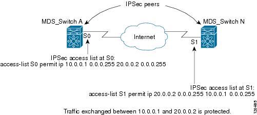
•![]() In Figure 7-17, IPsec protection is applied to traffic between switch interface S0 (IPv4 address 10.0.0.1) and switch interface S1 (IPv4 address 20.0.0.2) as the data exits switch A's S0 interface enroute to switch interface S1. For traffic from 10.0.0.1 to 20.0.0.2, the IPv4-ACL entry on switch A is evaluated as follows:
In Figure 7-17, IPsec protection is applied to traffic between switch interface S0 (IPv4 address 10.0.0.1) and switch interface S1 (IPv4 address 20.0.0.2) as the data exits switch A's S0 interface enroute to switch interface S1. For traffic from 10.0.0.1 to 20.0.0.2, the IPv4-ACL entry on switch A is evaluated as follows:
–![]() source = IPv4 address 10.0.0.1
source = IPv4 address 10.0.0.1
–![]() dest = IPv4 address 20.0.0.2
dest = IPv4 address 20.0.0.2
For traffic from 20.0.0.2 to 10.0.0.1, that same IPv4-ACL entry on switch A is evaluated as follows:
–![]() source = IPv4 address 20.0.0.2
source = IPv4 address 20.0.0.2
–![]() dest = IPv4 address 10.0.0.1
dest = IPv4 address 10.0.0.1
Figure 7-17 IPsec Processing of Crypto IPv4-ACLs
•![]() If you configure multiple statements for a given crypto IPv4-ACL that is used for IPsec, the first permit statement that is matched is used to determine the scope of the IPsec SA. Later, if traffic matches a different permit statement of the crypto IPv4-ACL, a new, separate IPsec SA is negotiated to protect traffic matching the newly matched IPv4-ACL statement.
If you configure multiple statements for a given crypto IPv4-ACL that is used for IPsec, the first permit statement that is matched is used to determine the scope of the IPsec SA. Later, if traffic matches a different permit statement of the crypto IPv4-ACL, a new, separate IPsec SA is negotiated to protect traffic matching the newly matched IPv4-ACL statement.
•![]() Unprotected inbound traffic that matches a permit entry in the crypto IPv4-ACL for a crypto map entry flagged as IPsec is dropped, because this traffic was expected to be protected by IPsec.
Unprotected inbound traffic that matches a permit entry in the crypto IPv4-ACL for a crypto map entry flagged as IPsec is dropped, because this traffic was expected to be protected by IPsec.
•![]() For IPsec to interoperate effectively with Microsoft iSCSI initiators, specify the TCP protocol and the local iSCSI TCP port number (default 3260) in the IPv4-ACL. This configuration ensures the speedy recovery of encrypted iSCSI sessions following disruptions such as Gigabit Ethernet interfaces shutdowns, VRRP switchovers, and port failures.
For IPsec to interoperate effectively with Microsoft iSCSI initiators, specify the TCP protocol and the local iSCSI TCP port number (default 3260) in the IPv4-ACL. This configuration ensures the speedy recovery of encrypted iSCSI sessions following disruptions such as Gigabit Ethernet interfaces shutdowns, VRRP switchovers, and port failures.
Mirror Image Crypto IPv4-ACLs
For every crypto IPv4-ACL specified for a crypto map entry defined at the local peer, define a mirror image crypto IPv4-ACL at the remote peer. This configuration ensures that IPsec traffic applied locally can be processed correctly at the remote peer.
Tip ![]() The crypto map entries themselves must also support common transforms and must refer to the other system as a peer.
The crypto map entries themselves must also support common transforms and must refer to the other system as a peer.
Figure 7-18 shows some sample scenarios with and without mirror image IPv4-ACLs.
Figure 7-18 IPsec Processing of Mirror Image Configuration
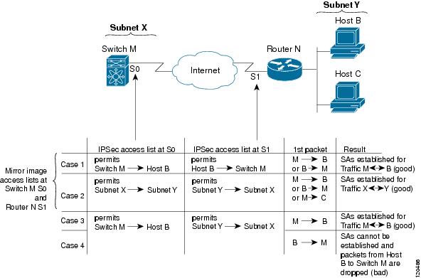
As Figure 7-18 indicates, IPsec SAs can be established as expected whenever the two peers' crypto IPv4-ACLs are mirror images of each other. However, an IPsec SA can be established only some of the time when the IPv4-ACLs are not mirror images of each other. This can happen in the case when an entry in one peer's IPv4-ACL is a subset of an entry in the other peer's IPv4-ACL, such as shown in cases 3 and 4 of Figure 7-18. IPsec SA establishment is critical to IPsec. Without SAs, IPsec does not work, causing any packets matching the crypto IPv4-ACL criteria to be silently dropped instead of being forwarded with IPsec security.
In case 4, an SA cannot be established because SAs are always requested according to the crypto IPv4-ACLs at the initiating packet's end. In case 4, router N requests that all traffic between subnet X and subnet Y be protected, but this is a superset of the specific flows permitted by the crypto IPv4-ACL at switch M so the request is not permitted. Case 3 works because switch M's request is a subset of the specific flows permitted by the crypto IPv4-ACL at router N.
Because of the complexities introduced when crypto IPv4-ACLs are not configured as mirror images at peer IPsec devices, we strongly encourage you to use mirror image crypto IPv4-ACLs.
The any Keyword in Crypto IPv4-ACLs
Tip ![]() We recommend that you configure mirror image crypto IPv4-ACLs for use by IPsec and that you avoid using the any option.
We recommend that you configure mirror image crypto IPv4-ACLs for use by IPsec and that you avoid using the any option.
The any keyword in a permit statement is discouraged when you have multicast traffic flowing through the IPsec interface. This configuration can cause multicast traffic to fail.
The permit any statement causes all outbound traffic to be protected (and all protected traffic sent to the peer specified in the corresponding crypto map entry) and requires protection for all inbound traffic. Then, all inbound packets that lack IPsec protection are silently dropped, including packets for routing protocols, NTP, echo, echo response, and so forth.
You need to be sure you define which packets to protect. If you must use any in a permit statement, you must preface that statement with a series of deny statements to filter out any traffic (that would otherwise fall within that permit statement) that you do not want to be protected.
Creating Crypto IPv4-ACLs
To create crypto IPv4-ACLs refer to the Chapter 5, "Configuring IPv4 and IPv6 Access Control Lists."
About Transform Sets in IPsec
A transform set represents a certain combination of security protocols and algorithms. During the IPsec security association negotiation, the peers agree to use a particular transform set for protecting a particular data flow.
You can specify multiple transform sets, and then specify one or more of these transform sets in a crypto map entry. The transform set defined in the crypto map entry is used in the IPsec security association negotiation to protect the data flows specified by that crypto map entry's access list.
During IPsec security association negotiations with IKE, the peers search for a transform set that is the same at both peers. When such a transform set is found, it is selected and applied to the protected traffic as part of both peers' IPsec security associations.
Tip ![]() If you change a transform set definition, the change is only applied to crypto map entries that reference the transform set. The change is not applied to existing security associations, but used in subsequent negotiations to establish new security associations. If you want the new settings to take effect sooner, you can clear all or part of the security association database.
If you change a transform set definition, the change is only applied to crypto map entries that reference the transform set. The change is not applied to existing security associations, but used in subsequent negotiations to establish new security associations. If you want the new settings to take effect sooner, you can clear all or part of the security association database.
Note ![]() When you enable IPsec, the Cisco NX-OS software automatically creates a default transform set (ipsec_default_tranform_set) using AES-128 encryption and SHA-1 authentication algorithms.
When you enable IPsec, the Cisco NX-OS software automatically creates a default transform set (ipsec_default_tranform_set) using AES-128 encryption and SHA-1 authentication algorithms.
Table 7-2 provides a list of allowed transform combinations for IPsec.
|
|
|
|
|---|---|---|
encryption algorithm |
56-bit DES-CBC 168-bit DES 128-bit AES-CBC 128-bit AES-CTR1 256-bit AES-CBC 256-bit AES-CTR1 |
esp-des esp-3des esp-aes 128 esp-aes 128 ctr esp-aes 256 esp-aes 256 ctr |
hash/authentication algorithm1 (optional) |
SHA-1 (HMAC variant) MD5 (HMAC variant) AES-XCBC-MAC |
esp-sha1-hmac esp-md5-hmac esp-aes-xcbc-mac |
1 If you configure the AES counter (CTR) mode, you must also configure the authentication algorithm. |
The following table lists the supported and verified settings for IPsec and IKE encryption authentication algorithms on the Microsoft Windows and Linux platforms:
Configuring Transform Sets
To configure transform sets using Fabric Manager, follow these steps:
Step 1 ![]() Expand Switches > Security and then select IPSec in the Physical Attributes pane.
Expand Switches > Security and then select IPSec in the Physical Attributes pane.
You see the IPSec configuration shown in Figure 7-19.
Figure 7-19 IPsec Configuration
Step 2 ![]() Click the Transform Set tab in the Information pane.
Click the Transform Set tab in the Information pane.
Step 3 ![]() Click Create Row.
Click Create Row.
You see the Create IPSEC dialog box shown in Figure 7-20.
Figure 7-20 Create IPSEC
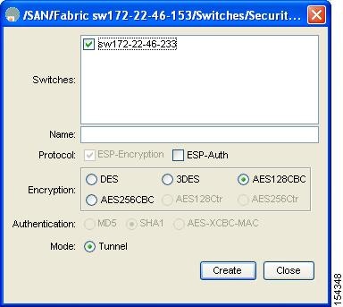
Step 4 ![]() Select the switches that you want to create a transform set for in the Create Transform Set dialog box.
Select the switches that you want to create a transform set for in the Create Transform Set dialog box.
Step 5 ![]() Assign a name and protocol for the transform set.
Assign a name and protocol for the transform set.
Step 6 ![]() Select the encryption and authentication algorithm. See Table 7-2 to verify the allowed transform combinations.
Select the encryption and authentication algorithm. See Table 7-2 to verify the allowed transform combinations.
Step 7 ![]() Click Create to create the transform set or you click Close.
Click Create to create the transform set or you click Close.
About Crypto Map Entries
Once you have created the crypto IPv4-ACLs and transform sets, you can create crypto map entries that combine the various parts of the IPsec SA, including the following:
•![]() The traffic to be protected by IPsec (per the crypto IPv4-ACL). A crypto map set can contain multiple entries, each with a different IPv4-ACL.
The traffic to be protected by IPsec (per the crypto IPv4-ACL). A crypto map set can contain multiple entries, each with a different IPv4-ACL.
•![]() The granularity of the flow to be protected by a set of SAs.
The granularity of the flow to be protected by a set of SAs.
•![]() The IPsec-protected traffic destination (who the remote IPsec peer is).
The IPsec-protected traffic destination (who the remote IPsec peer is).
•![]() The local address to be used for the IPsec traffic (applying to an interface).
The local address to be used for the IPsec traffic (applying to an interface).
•![]() The IPsec security to be applied to this traffic (selecting from a list of one or more transform sets).
The IPsec security to be applied to this traffic (selecting from a list of one or more transform sets).
•![]() Other parameters to define an IPsec SA.
Other parameters to define an IPsec SA.
Crypto map entries with the same crypto map name (but different map sequence numbers) are grouped into a crypto map set.
When you apply a crypto map set to an interface, the following events occur:
•![]() A security policy database (SPD) is created for that interface.
A security policy database (SPD) is created for that interface.
•![]() All IP traffic passing through the interface is evaluated against the SPD.
All IP traffic passing through the interface is evaluated against the SPD.
If a crypto map entry sees outbound IP traffic that requires protection, an SA is negotiated with the remote peer according to the parameters included in the crypto map entry.
The policy derived from the crypto map entries is used during the negotiation of SAs. If the local switch initiates the negotiation, it will use the policy specified in the crypto map entries to create the offer to be sent to the specified IPsec peer. If the IPsec peer initiates the negotiation, the local switch checks the policy from the crypto map entries and decides whether to accept or reject the peer's request (offer).
For IPsec to succeed between two IPsec peers, both peers' crypto map entries must contain compatible configuration statements.
SA Establishment Between Peers
When two peers try to establish an SA, they must each have at least one crypto map entry that is compatible with one of the other peer's crypto map entries.
For two crypto map entries to be compatible, they must at least meet the following criteria:
•![]() The crypto map entries must contain compatible crypto IPv4-ACLs (for example, mirror image IPv4-ACLs). If the responding peer entry is in the local crypto, the IPv4-ACL must be permitted by the peer's crypto IPv4-ACL.
The crypto map entries must contain compatible crypto IPv4-ACLs (for example, mirror image IPv4-ACLs). If the responding peer entry is in the local crypto, the IPv4-ACL must be permitted by the peer's crypto IPv4-ACL.
•![]() The crypto map entries must each identify the other peer or must have auto peer configured.
The crypto map entries must each identify the other peer or must have auto peer configured.
•![]() If you create more than one crypto map entry for a given interface, use the seq-num of each map entry to rank the map entries: the lower the seq-num, the higher the priority. At the interface that has the crypto map set, traffic is evaluated against higher priority map entries first.
If you create more than one crypto map entry for a given interface, use the seq-num of each map entry to rank the map entries: the lower the seq-num, the higher the priority. At the interface that has the crypto map set, traffic is evaluated against higher priority map entries first.
•![]() The crypto map entries must have at least one transform set in common, where IKE negotiations are carried out and SAs are established. During the IPsec SA negotiation, the peers agree to use a particular transform set when protecting a particular data flow.
The crypto map entries must have at least one transform set in common, where IKE negotiations are carried out and SAs are established. During the IPsec SA negotiation, the peers agree to use a particular transform set when protecting a particular data flow.
When a packet matches a permit entry in a particular IPv4-ACL, the corresponding crypto map entry is tagged, and the connections are established.
Crypto Map Configuration Guidelines
When configuring crypto map entries, follow these guidelines:
•![]() The sequence number for each crypto map decides the order in which the policies are applied. A lower sequence number is assigned a higher priority.
The sequence number for each crypto map decides the order in which the policies are applied. A lower sequence number is assigned a higher priority.
•![]() Only one IPv4-ACL is allowed for each crypto map entry (the IPv4-ACL itself can have multiple permit or deny entries).
Only one IPv4-ACL is allowed for each crypto map entry (the IPv4-ACL itself can have multiple permit or deny entries).
•![]() When the tunnel endpoint is the same as the destination address, you can use the auto-peer option to dynamically configure the peer.
When the tunnel endpoint is the same as the destination address, you can use the auto-peer option to dynamically configure the peer.
•![]() For IPsec to interoperate effectively with Microsoft iSCSI initiators, specify the TCP protocol and the local iSCSI TCP port number (default 3260) in the IPv4-ACL. This configuration ensures the speedy recovery of encrypted iSCSI sessions following disruptions such as Gigabit Ethernet interfaces shutdowns, VRRP switchovers, and port failures.
For IPsec to interoperate effectively with Microsoft iSCSI initiators, specify the TCP protocol and the local iSCSI TCP port number (default 3260) in the IPv4-ACL. This configuration ensures the speedy recovery of encrypted iSCSI sessions following disruptions such as Gigabit Ethernet interfaces shutdowns, VRRP switchovers, and port failures.
Creating Crypto Map Entries
To create mandatory crypto map entries using Fabric Manager, follow these steps:
Step 1 ![]() Expand Switches > Security and then select IPSEC in the Physical Attributes pane.
Expand Switches > Security and then select IPSEC in the Physical Attributes pane.
You see the IPsec configuration in the Information pane (see Figure 7-21).
Figure 7-21 IPsec Configuration
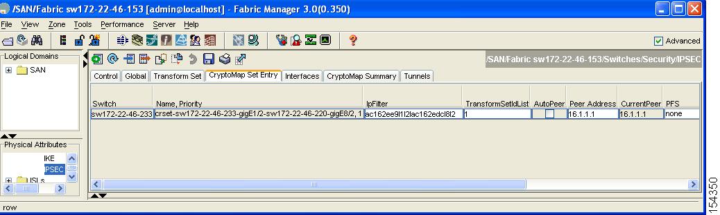
Step 2 ![]() Choose the CryptoMap Set Entry tab.
Choose the CryptoMap Set Entry tab.
You see the existing crypto maps configured (see Figure 7-22).
Figure 7-22 Existing Crypto Maps
Step 3 ![]() (Optional) Click Create Row to create a crypto map entry.
(Optional) Click Create Row to create a crypto map entry.
You see the Create Crypto Map dialog box shown in Figure 7-23.
Figure 7-23 Create Crypto Map Dialog Box
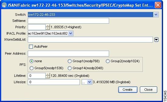
Step 4 ![]() Select the switch that you want to configure or modify. If you are creating a crypto map, set the setName and priority for this crypto map.
Select the switch that you want to configure or modify. If you are creating a crypto map, set the setName and priority for this crypto map.
Step 5 ![]() Select the IPv4-ACL Profile and TransformSetIdList from the drop-down list for this crypto map.
Select the IPv4-ACL Profile and TransformSetIdList from the drop-down list for this crypto map.
Step 6 ![]() (Optional) Check the AutoPeer check box or set the peer address if you are creating a crypto map. See the "About the AutoPeer Option" section.
(Optional) Check the AutoPeer check box or set the peer address if you are creating a crypto map. See the "About the AutoPeer Option" section.
Step 7 ![]() Choose the appropriate PFS selection. See the "About Perfect Forward Secrecy" section.
Choose the appropriate PFS selection. See the "About Perfect Forward Secrecy" section.
Step 8 ![]() Supply the Lifetime and LifeSize. See the "About SA Lifetime Negotiation" section.
Supply the Lifetime and LifeSize. See the "About SA Lifetime Negotiation" section.
Step 9 ![]() Click Create if you are creating a crypto map, or click Apply Changes if you are modifying an existing crypto map.
Click Create if you are creating a crypto map, or click Apply Changes if you are modifying an existing crypto map.
About SA Lifetime Negotiation
You can override the global lifetime values (size and time) by configuring an SA-specific lifetime value.
To specify SA lifetime negotiation values, you can optionally configure the lifetime value for a specified crypto map. If you do, this value overrides the globally set values. If you do not specify the crypto map specific lifetime, the global value (or global default) is used.
See the "Global Lifetime Values" section for more information on global lifetime values.
Setting the SA Lifetime
To set the SA lifetime for a specified crypto map entry using Fabric Manager, follow these steps:
Step 1 ![]() Expand Switches > Security and then select IPSEC in the Physical Attributes pane.
Expand Switches > Security and then select IPSEC in the Physical Attributes pane.
You see the IP SEC configuration in the Information pane (see Figure 7-24).
Figure 7-24 IPsec Configuration
Step 2 ![]() Choose the CryptoMap Set Entry tab.
Choose the CryptoMap Set Entry tab.
You see the existing crypto maps configured (see Figure 7-25).
Figure 7-25 Existing Crypto Maps - Leftmost Columns
Step 3 ![]() Scroll to the right half of the dialog box.
Scroll to the right half of the dialog box.
You see more columns shown in Figure 7-26.
Figure 7-26 Existing Crypto Maps - Rightmost Columns

Step 4 ![]() Double-click and modify the value in the Life Time(sec) column.
Double-click and modify the value in the Life Time(sec) column.
Step 5 ![]() Click Apply Changes to save your changes.
Click Apply Changes to save your changes.
About the AutoPeer Option
Setting the peer address as AutoPeer in the crypto map indicates that the destination endpoint of the traffic should be used as the peer address for the SA. Using the same crypto map, a unique SA can be set up at each of the endpoints in the subnet specified by the crypto map's IPv4-ACL entry. Auto-peer simplifies configuration when traffic endpoints are IPsec capable. It is particularly useful for iSCSI, where the iSCSI hosts in the same subnet do not require separate configuration.
Figure 7-27 shows a scenario where the auto-peer option can simplify configuration. Using the auto-peer option, only one crypto map entry is needed for all the hosts from subnet X to set up SAs with the switch. Each host will set up its own SA, but will share the crypto map entry. Without the auto-peer option, each host needs one crypto map entry.
Figure 7-27 iSCSI with End-to-End IPsec Using the auto-peer Option
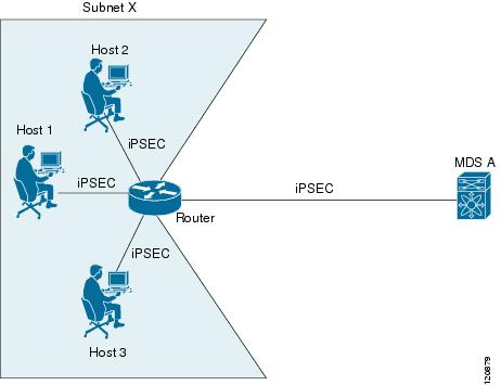
Configuring the AutoPeer Option
To configure the AutoPeer option using Fabric Manager, follow these steps:
Step 1 ![]() Expand Switches > Security and then select IPSEC in the Physical Attributes pane.
Expand Switches > Security and then select IPSEC in the Physical Attributes pane.
You see the IPsec configuration in the Information pane (see Figure 7-28).
Figure 7-28 IPsec Configuration
Step 2 ![]() Click the CryptoMap Set Entry tab.
Click the CryptoMap Set Entry tab.
You see the existing crypto maps configured in Figure 7-29.
Figure 7-29 Existing Crypto Maps
Step 3 ![]() Check or uncheck the AutoPeer option for the selected crypto map set entry.
Check or uncheck the AutoPeer option for the selected crypto map set entry.
Step 4 ![]() Click Apply Changes to save your changes.
Click Apply Changes to save your changes.
About Perfect Forward Secrecy
To specify SA lifetime negotiation values, you can also optionally configure the perfect forward secrecy (PFS) value in the crypto map.
The PFS feature is disabled by default. If you set the PFS group, you can set one of the DH groups: 1, 2, 5, or 14. If you do not specify a DH group, the software uses group 1 by default.
Configuring Perfect Forward Secrecy
To configure the PFS value using Fabric Manager, follow these steps:
Step 1 ![]() Expand Switches > Security and then select IPSEC in the Physical Attributes pane.
Expand Switches > Security and then select IPSEC in the Physical Attributes pane.
You see the IPsec configuration in the Information pane (see Figure 7-30).
Figure 7-30 IPsec Configuration
Step 2 ![]() Click the CryptoMap Set Entry tab.
Click the CryptoMap Set Entry tab.
You see the existing crypto maps configured in Figure 7-31.
Figure 7-31 Existing Crypto Maps
Step 3 ![]() In the drop-down list in the PFS column select the appropriate value.
In the drop-down list in the PFS column select the appropriate value.
Step 4 ![]() Click Apply Changes to save your changes.
Click Apply Changes to save your changes.
About Crypto Map Set Application
You need to apply a crypto map set to each interface through which IPsec traffic will flow. Applying the crypto map set to an interface instructs the switch to evaluate all the interface's traffic against the crypto map set and to use the specified policy during connection or SA negotiation on behalf of the traffic to be protected by crypto.
You can apply only one crypto map set to an interface. You can apply the same crypto map to multiple interfaces. However, you cannot apply more than one crypto map set to each interface.
Applying a Crypto Map Set
To apply a crypto map set to an interface using Fabric Manager, follow these steps:
Step 1 ![]() Expand Switches > Security and then select IPSEC in the Physical Attributes pane.
Expand Switches > Security and then select IPSEC in the Physical Attributes pane.
You see the IPsec configuration in the Information pane (see Figure 7-32).
Figure 7-32 IPsec Configuration
Step 2 ![]() Click the Interfaces tab.
Click the Interfaces tab.
You see the existing interface to crypto map configuration in Figure 7-33.
Figure 7-33 Crypto Map Interfaces
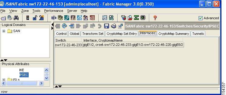
Step 3 ![]() Select the switch and interface you want to configure.
Select the switch and interface you want to configure.
Step 4 ![]() Enter the name of the crypto map that you want to apply to this interface in the CryptomapSetName field.
Enter the name of the crypto map that you want to apply to this interface in the CryptomapSetName field.
Step 5 ![]() Click Create to apply the crypto map to the selected interface or click Close to exit the dialog box without applying the crypto map.
Click Create to apply the crypto map to the selected interface or click Close to exit the dialog box without applying the crypto map.
IPsec Maintenance
Certain configuration changes will only take effect when negotiating subsequent security associations. If you want the new settings to take immediate effect, you must clear the existing security associations so that they will be reestablished with the changed configuration. If the switch is actively processing IPsec traffic, it is desirable to clear only the portion of the security association database that would be affected by the configuration changes (that is, clear only the security associations established by a given crypto map set). Clearing the full security association database should be reserved for large-scale changes, or when the router is processing very little other IPsec traffic.
Global Lifetime Values
If you have not configured a lifetime in the crypto map entry, the global lifetime values are used when negotiating new IPsec SAs.
You can configure two lifetimes: timed or traffic-volume. An SA expires after the first of these lifetimes is reached. The default lifetimes are 3,600 seconds (one hour) and 450 GB.
If you change a global lifetime, the new lifetime value will not be applied to currently existing SAs, but will be used in the negotiation of subsequently established SAs. If you wish to use the new values immediately, you can clear all or part of the SA database.
Assuming that the particular crypto map entry does not have lifetime values configured, when the switch requests new SAs it will specify its global lifetime values in the request to the peer; it will use this value as the lifetime of the new SAs. When the switch receives a negotiation request from the peer, it uses the value determined by the IKE version in use:
•![]() If you use IKEv1 to set up IPsec SAs, the SA lifetime values are chosen to be the smaller of the two proposals. The same values are programmed on both the ends of the tunnel.
If you use IKEv1 to set up IPsec SAs, the SA lifetime values are chosen to be the smaller of the two proposals. The same values are programmed on both the ends of the tunnel.
•![]() If you use IKEv2 to set up IPsec SAs, the SAs on each end have their own set up of lifetime values and thus the SAs on both sides expire independently.
If you use IKEv2 to set up IPsec SAs, the SAs on each end have their own set up of lifetime values and thus the SAs on both sides expire independently.
The SA (and corresponding keys) will expire according to whichever comes sooner, either after the specified amount of time (in seconds) has passed or after the specified amount of traffic (in bytes) has passed.
A new SA is negotiated before the lifetime threshold of the existing SA is reached to ensure that negotiation completes before the existing SA expires.
The new SA is negotiated when one of the following thresholds is reached (whichever comes first):
•![]() 30 seconds before the lifetime expires or
30 seconds before the lifetime expires or
•![]() Approximately 10% of the lifetime in bytes remain
Approximately 10% of the lifetime in bytes remain
If no traffic has passed through when the lifetime expires, a new SA is not negotiated. Instead, a new SA will be negotiated only when IPsec sees another packet that should be protected.
To configure global SA lifetimes using Fabric Manager, follow these steps:
Step 1 ![]() Choose Switches > Security and then select IPSEC in the Physical Attributes pane.
Choose Switches > Security and then select IPSEC in the Physical Attributes pane.
Step 2 ![]() You see the IPsec configuration in the Information pane.
You see the IPsec configuration in the Information pane.
Step 3 ![]() Click the Global tab.
Click the Global tab.
Step 4 ![]() Double-click and edit the value in the Life Time(sec) column (see Figure 7-34).
Double-click and edit the value in the Life Time(sec) column (see Figure 7-34).
Figure 7-34 IPsec Configuration Global Tab
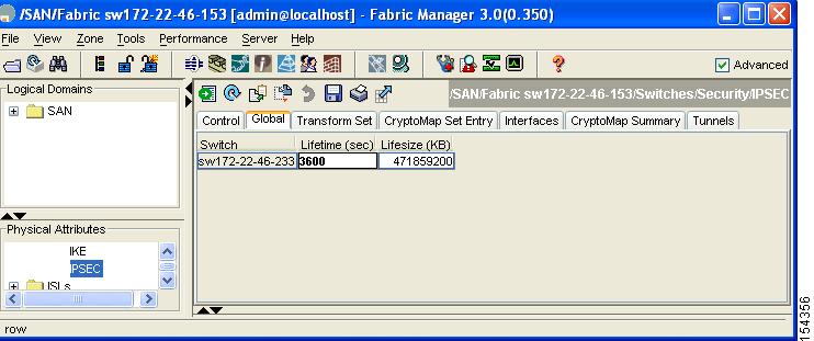
Step 5 ![]() Click Apply Changes to save your changes.
Click Apply Changes to save your changes.
Default Settings
Table 7-3 lists the default settings for IKE parameters.
Table 7-4 lists the default settings for IPsec parameters.
 Feedback