- Index
- New and Changed Information
- Preface
- Overview
- Configuring FIPS
- Configuring Users and Common Roles
- Configuring RADIUS and TACACS+
- Configuring IPv4 and IPv6 Access Control Lists
- Configuring Certificate Authorities and Digital Certificates
- Configuring IPSec Network Security
- Configuring FC-SP and DHCHAP
- Configuring Port Security
- Configuring Fabric Binding
- Configuring Cisco TrustSec Fibre Channel Link Encryption
Configuring Cisco TrustSec Fibre Channel Link Encryption
This chapter provides an overview of the Cisco TrustSec Fibre Channel (FC) Link Encryption feature and describes how to configure and set up link-level encryption between switches.
The chapter includes the following sections:
•![]() Cisco TrustSec FC Link Encryption Terminology
Cisco TrustSec FC Link Encryption Terminology
•![]() About Cisco TrustSec FC Link Encryption
About Cisco TrustSec FC Link Encryption
•![]() Configuring ESP Using ESP Wizard
Configuring ESP Using ESP Wizard
•![]() Viewing Cisco TrustSec FC Link Encryption Statistics
Viewing Cisco TrustSec FC Link Encryption Statistics
•![]() Cisco TrustSec FC Link Encryption Best Practices
Cisco TrustSec FC Link Encryption Best Practices
Cisco TrustSec FC Link Encryption Terminology
The following Cisco TrustSec FC Link Encryption-related terms are used in this chapter:
•![]() Galois Counter Mode (GCM)—A block cipher mode of operation providing confidentiality and data-origin authentication.
Galois Counter Mode (GCM)—A block cipher mode of operation providing confidentiality and data-origin authentication.
•![]() Galois Message Authentication Code (GMAC)—A block cipher mode of operation providing only data-origin authentication. It is the authentication-only variant of GCM.
Galois Message Authentication Code (GMAC)—A block cipher mode of operation providing only data-origin authentication. It is the authentication-only variant of GCM.
•![]() Security Association (SA)—A connection that handles the security credentials and controls how they propagate between switches. The SA includes parameters such as salt and keys.
Security Association (SA)—A connection that handles the security credentials and controls how they propagate between switches. The SA includes parameters such as salt and keys.
•![]() Key—A 128-bit hexadecimal string that is used for frame encryption and decryption. The default value is zero.
Key—A 128-bit hexadecimal string that is used for frame encryption and decryption. The default value is zero.
•![]() Salt —A 32-bit hexadecimal number that is used during encryption and decryption. The same salt must be configured on both sides of the connection to ensure proper communication. The default value is zero.
Salt —A 32-bit hexadecimal number that is used during encryption and decryption. The same salt must be configured on both sides of the connection to ensure proper communication. The default value is zero.
•![]() Security Parameters Index (SPI) number—A 32-bit number that identifies the SA to be configured to the hardware. The range is from 256 to 4,294,967,295.
Security Parameters Index (SPI) number—A 32-bit number that identifies the SA to be configured to the hardware. The range is from 256 to 4,294,967,295.
Support for AES Encryption
The Advanced Encryption Standard (AES) is the symmetric cipher algorithm that provides a high-level of security, and can accept different key sizes.
The Cisco TrustSec FC Link Encryption feature supports the 128-bit AES for security encryption and enables either AES-GCM or AES-GMAC for an interface. The AES-GCM mode provides encryption and authentication of the frames and AES-GMAC provides only the authentication of the frames that are being passed between the two peers.
About Cisco TrustSec FC Link Encryption
Cisco TrustSec FC Link Encryption is an extension of the Fibre Channel-Security Protocol (FC-SP) feature and uses the existing FC-SP architecture to provide integrity and confidentiality of transactions. Encryption is now added to the peer authentication capability to provide security and prevent unwanted traffic interception. Peer authentication is implemented according to the FC-SP standard using the Diffie-Hellman Challenge Handshake Authentication Protocol (DHCHAP) protocol.

Note ![]() Cisco TrustSec FC Link Encryption is currently only supported between Cisco MDS switches. This feature is not supported when you downgrade to software versions which do not have the Encapsulating Security Protocol (ESP) support.
Cisco TrustSec FC Link Encryption is currently only supported between Cisco MDS switches. This feature is not supported when you downgrade to software versions which do not have the Encapsulating Security Protocol (ESP) support.
This section includes the following topics:
•![]() Enabling Cisco TrustSec FC Link Encryption
Enabling Cisco TrustSec FC Link Encryption
•![]() Setting Up Security Associations
Setting Up Security Associations
•![]() Setting Up Security Association Parameters
Setting Up Security Association Parameters
Supported Modules
The following modules are supported for the Cisco TrustSec FC Link Encryption feature:
•![]() 1/2/4/8 Gbps 24-Port Fibre Channel switching module (DS-X9224-96K9)
1/2/4/8 Gbps 24-Port Fibre Channel switching module (DS-X9224-96K9)
•![]() 1/2/4/8 Gbps 48-Port Fibre Channel switching module (DS-X9248-96K9)
1/2/4/8 Gbps 48-Port Fibre Channel switching module (DS-X9248-96K9)
•![]() 1/2/4/8 Gbps 4/44-Port Fibre Channel switching module (DS-X9248-48K9)
1/2/4/8 Gbps 4/44-Port Fibre Channel switching module (DS-X9248-48K9)
Enabling Cisco TrustSec FC Link Encryption
By default, the FC-SP feature and the Cisco TrustSec FC Link Encryption feature are disabled in all switches in the Cisco MDS 9000 Family.
You must explicitly enable the FC-SP feature to access the configuration and verification commands for fabric authentication and encryption. When you disable this feature, all related configurations are automatically discarded.
Configuring the Cisco TrustSec FC Link Encryption feature requires the ENTERPRISE_PKG license. For more information, refer to the Cisco MDS 9000 Family NX-OS Licensing Guide.
Setting Up Security Associations
To perform encryption between the switches, a security association (SA) needs to be set up. An administrator manually configures the SA before the encryption can take place. The SA includes parameters such as keys and salt, that are required for encryption. You can set up to 2000 SAs in a switch.
Note ![]() Cisco TrustSec FC Link Encryption is currently supported only on DHCHAP on and off modes.
Cisco TrustSec FC Link Encryption is currently supported only on DHCHAP on and off modes.
Setting Up Security Association Parameters
To set up the SA parameters, such as keys and salt, using Fabric Manager, follow these steps:
Step 1 ![]() Expand Switches > Security and then select FC-SP (DHCHAP).
Expand Switches > Security and then select FC-SP (DHCHAP).
You see the FC-SP configuration in the Information pane.
Step 2 ![]() Click the SA tab.
Click the SA tab.
You see the SA parameters for each switch (see Figure 10-1).
Figure 11-1 SA Tab
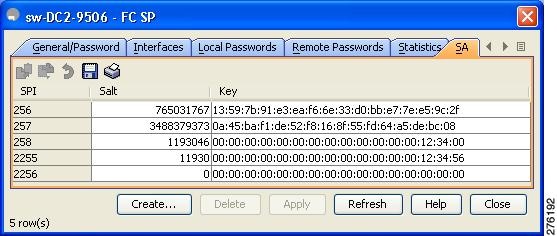
Step 3 ![]() Click the Create Row icon (see Figure 10-1).
Click the Create Row icon (see Figure 10-1).
Figure 11-2
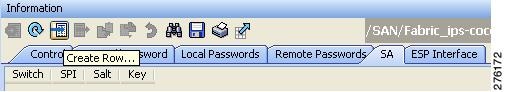
Create Row Icon
You see the Create SA Parameters dialog box (see Figure 10-2).
Figure 11-3
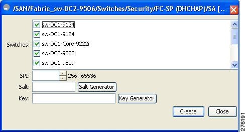
Create SA Parameters
Step 4 ![]() Select the switches on which you want to perform an encryption.
Select the switches on which you want to perform an encryption.
Step 5 ![]() Select a value for the SP. The range is from 256 to 65536.
Select a value for the SP. The range is from 256 to 65536.
Step 6 ![]() Enter a value for the salt. Alternatively, click Salt Generator to select a value
Enter a value for the salt. Alternatively, click Salt Generator to select a value
Step 7 ![]() Enter a value for the key. Alternatively, click Key Generator to select a value.
Enter a value for the key. Alternatively, click Key Generator to select a value.
Step 8 ![]() Click Create to save the changes.
Click Create to save the changes.
To set up the SA parameters, such as keys and salt, using Device Manager, follow these steps:
Step 1 ![]() Choose Switches > Security and then select FC-SP.
Choose Switches > Security and then select FC-SP.
You see the FC-SP configuration dialog box.
Step 2 ![]() Click the SA tab.
Click the SA tab.
You see the SA parameters for each switch (see Figure 11-4).
Figure 11-4 SA
Step 3 ![]() Click Create to create new parameters.
Click Create to create new parameters.
You see the Create FC-SP SA dialog box (see Figure 10-2).
Figure 11-5
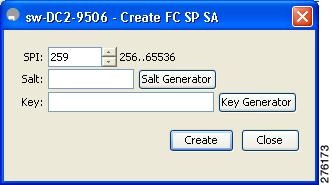
Create FC-SP SA
Step 4 ![]() Select a value for the SP. The range is from 256 to 65536.
Select a value for the SP. The range is from 256 to 65536.
Step 5 ![]() Enter a value for the salt. Alternatively, click Salt Generator to select a value
Enter a value for the salt. Alternatively, click Salt Generator to select a value
Step 6 ![]() Enter a value for the key. Alternatively, click Key Generator to select a value.
Enter a value for the key. Alternatively, click Key Generator to select a value.
Step 7 ![]() Click Create to save the changes.
Click Create to save the changes.
Configuring ESP Settings
To configure ESP settings using Fabric Manager, follow these steps:
Step 1 ![]() Expand Switches > Security and then select FC-SP (DHCHAP).
Expand Switches > Security and then select FC-SP (DHCHAP).
You see the FC-SP configuration in the Information pane.
Step 2 ![]() Click the ESP Interfaces tab.
Click the ESP Interfaces tab.
You see the Interface details for each switch (see Figure 10-4).
Figure 11-6 ESP Interfaces Tab
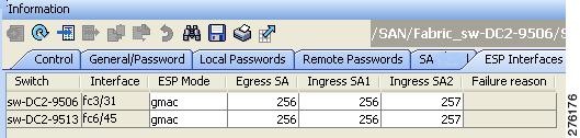
Step 3 ![]() Click the Create Row icon.
Click the Create Row icon.
You see the Create ESP Interfaces dialog box (see Figure 10-2).
Figure 11-7
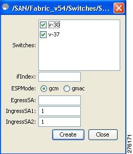
Create ESP Interfaces
Step 4 ![]() Select the switches on which you want to perform an encryption.
Select the switches on which you want to perform an encryption.
Step 5 ![]() Enter an interface for the selected switch.
Enter an interface for the selected switch.
Step 6 ![]() Select the appropriate ESP mode for the encryption.
Select the appropriate ESP mode for the encryption.
Step 7 ![]() Enter the appropriate egress port for the encryption.
Enter the appropriate egress port for the encryption.
Step 8 ![]() Enter the appropriate ingress port for the encryption.
Enter the appropriate ingress port for the encryption.
Step 9 ![]() Click Create to save the changes.
Click Create to save the changes.
To configure ESP settings using Device Manager, follow these steps:
Step 1 ![]() Expand Switches > Security and then select FC-SP.
Expand Switches > Security and then select FC-SP.
You see the FC-SP configuration dialog box.
Step 2 ![]() Click the ESP Interfaces tab.
Click the ESP Interfaces tab.
You see the Interface details for each switch (see Figure 11-8).
Figure 11-8 ESP Interfaces Tab
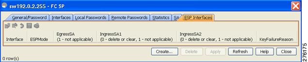
Step 3 ![]() Click Create.
Click Create.
You see the Create FC-SP ESP Interfaces dialog box (see Figure 11-9).
Figure 11-9
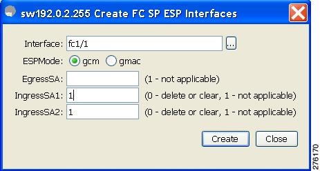
Create ESP Interfaces
Step 4 ![]() Enter an interace for any switch for encryption. Alternatively, you can select values from the available interfaces for the selected switch (see Figure 11-10).
Enter an interace for any switch for encryption. Alternatively, you can select values from the available interfaces for the selected switch (see Figure 11-10).
Figure 11-10 Available Interfaces
Step 5 ![]() Select the appropriate ESP mode for the encryption.
Select the appropriate ESP mode for the encryption.
Step 6 ![]() Enter the appropriate egress port for the encryption.
Enter the appropriate egress port for the encryption.
Step 7 ![]() Enter the appropriate ingress port for the encryption.
Enter the appropriate ingress port for the encryption.
Step 8 ![]() Click Create to save the changes.
Click Create to save the changes.
Configuring ESP Using ESP Wizard
You can configure and set up link-level encryption between switches, using Fabric Manager. You can configure an existing Inter-Switch Link (ISL) as a secure ISL or edit an existing secure ingress SPI and egress SPI using this wizard.
To configure ESP using ESP wizard, follow these steps:
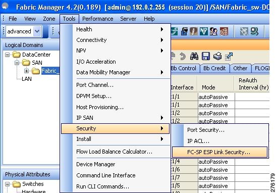
Step 1 ![]() Right-click Tools > Security> FC-SP ESP Link Security to launch the ESP wizard from Fabric Manager (see Figure 11-11).
Right-click Tools > Security> FC-SP ESP Link Security to launch the ESP wizard from Fabric Manager (see Figure 11-11).
Figure 11-11 Launching FC-SP ESP Wizard
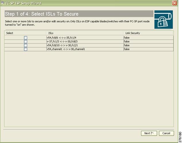
Step 2 ![]() Select the appropriate ISL to secure or edit security, as shown in Figure 11-12.
Select the appropriate ISL to secure or edit security, as shown in Figure 11-12.
Note ![]() Only ISLs with FC-SP port mode turned on and available on ESP capable switches or blades are displayed.
Only ISLs with FC-SP port mode turned on and available on ESP capable switches or blades are displayed.
Figure 11-12 Select ISL To Secure
Step 3 ![]() Create new Security Associations (SAs) as shown in Figure 11-13.
Create new Security Associations (SAs) as shown in Figure 11-13.
Figure 11-13
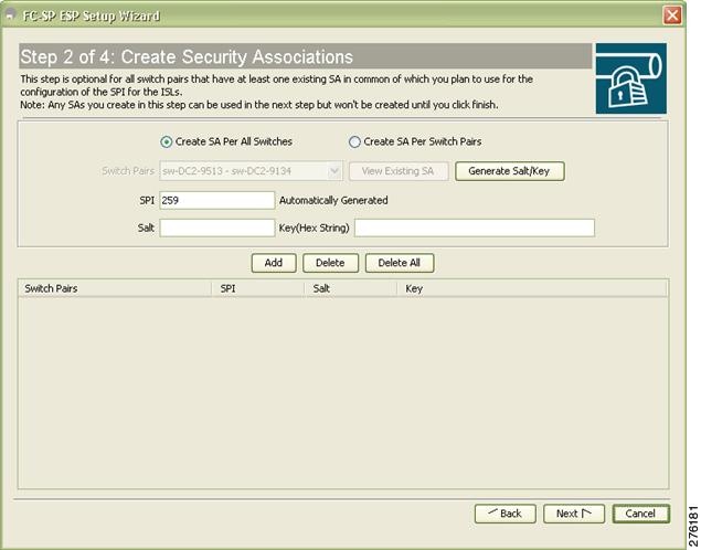
Create Security Associations
You can create a new SA for each switch or use the existing SAs. You can click View Existing SA to view the existing SAs.
Note ![]() The existing list of SAs displays all existing SAs for a switch. The wizard runs only when a pair of switches have a common SA. The wizard checks for this requirement when you select Next and a warning message is displayed if a pair of switches do not have a common SA. You must create a common SA on the pair of the switches to run this wizard.
The existing list of SAs displays all existing SAs for a switch. The wizard runs only when a pair of switches have a common SA. The wizard checks for this requirement when you select Next and a warning message is displayed if a pair of switches do not have a common SA. You must create a common SA on the pair of the switches to run this wizard.
Step 4 ![]() Specify the Egress port, Ingress port, and ESP mode for the selected ISL, as seen in Figure 11-14.
Specify the Egress port, Ingress port, and ESP mode for the selected ISL, as seen in Figure 11-14.
The Egress and Ingress ports are auto populated with SPIs of the SAs common to a pair of switches incase of a secured ISL.
In this scenario, the mode is disabled and you cannot edit the modes for a secured ISL.
Figure 11-14 Specify SPIs for ISLs
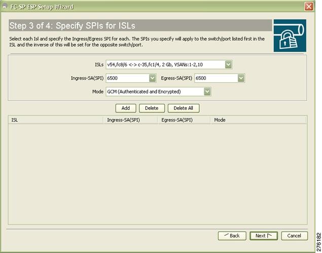
Note ![]() You can modify an existing ESP configuration provided the selected ISLs are enabled.
You can modify an existing ESP configuration provided the selected ISLs are enabled.
Step 5 ![]() Review your configuration as seen in Figure 11-15.
Review your configuration as seen in Figure 11-15.
Figure 11-15
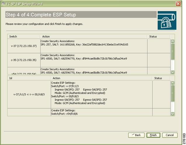
Complete ESP Setup
Step 6 ![]() Click Finish to start the configuration for the ESP setup. You can view the status of the configuration in the status column.
Click Finish to start the configuration for the ESP setup. You can view the status of the configuration in the status column.
Viewing Cisco TrustSec FC Link Encryption Statistics
You can view information about the Cisco TrustSec FC Link Encryption featureusingFabric Manager or Device Manager
This section covers the following topics:
•![]() Viewing FC-SP Interace Statistics Using Fabric Manager
Viewing FC-SP Interace Statistics Using Fabric Manager
•![]() Viewing FC-SP Interface Statistics Using Device Manager
Viewing FC-SP Interface Statistics Using Device Manager
Viewing FC-SP Interace Statistics Using Fabric Manager
You can view the statistics data that displays the Encapsulating Security Protocol-ESP Security Parameter (SPI) mismatches and Interface-Encapsulating Security Protocol authentication failures information using Fabric Manager.
To view the ESP statistics for an interface using Fabric Manager, follow these steps:
Step 1 ![]() Expand Interfaces > FC Physical and then select FC-SP.
Expand Interfaces > FC Physical and then select FC-SP.
You see the FC-SP configuration in the Information pane.
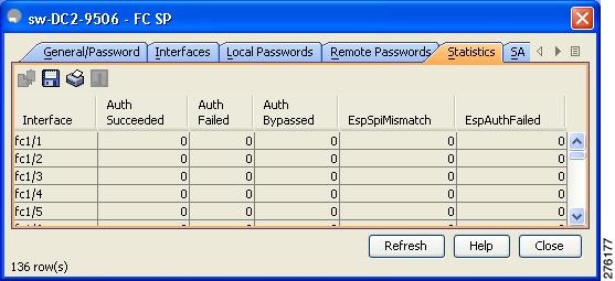
Step 2 ![]() Click the FC-SP tab.
Click the FC-SP tab.
You see view the FC-SP statistics data in the Information pane (see Figure 11-16).
Figure 11-16 FC-SP Statistics in Fabric Manager
Step 3 ![]() Click Refresh to refresh the statistics data.
Click Refresh to refresh the statistics data.
Viewing FC-SP Interface Statistics Using Device Manager
To view the ESP statistics for an interface using Device Manager, follow these steps:
Step 1 ![]() Choose Security > FC Physical and then select FC-SP.
Choose Security > FC Physical and then select FC-SP.
You see the FC-SP configuration in the Information pane.
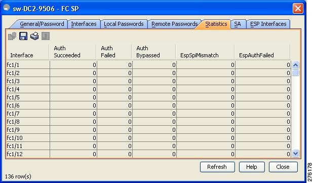
Step 2 ![]() Click the Statistics tab.
Click the Statistics tab.
You see the statistics in the Information pane (see Figure 11-17).
Figure 11-17 FC-SP Statistics in Device Manager
Step 3 ![]() Click Refresh to refresh the statistics data.
Click Refresh to refresh the statistics data.
Cisco TrustSec FC Link Encryption Best Practices
Best practices are the recommended steps that should be taken to ensure the proper operation of Cisco TrustSec FC Link Encryption.
This section covers the following topics:
•![]() Best Practices for Changing Keys
Best Practices for Changing Keys
General Best Practices
This section lists the general best practices for Cisco TrustSec FC Link Encryption:
•![]() Ensure that Cisco TrustSec FC Link Encryption is enabled only between MDS switches. This feature is supported only on E-ports or the ISLs, and errors will result if non-MDS switches are used.
Ensure that Cisco TrustSec FC Link Encryption is enabled only between MDS switches. This feature is supported only on E-ports or the ISLs, and errors will result if non-MDS switches are used.
•![]() Ensure that the peers in the connection have the same configurations. If there are differences in the configurations, a "port re-init limit exceeded" error message is displayed.
Ensure that the peers in the connection have the same configurations. If there are differences in the configurations, a "port re-init limit exceeded" error message is displayed.
•![]() Before applying the SA to the ingress and egress hardware of a switch interface, ensure that the interface is in the admin shut mode.
Before applying the SA to the ingress and egress hardware of a switch interface, ensure that the interface is in the admin shut mode.
Best Practices for Changing Keys
After the SA is applied to the ingress and egress ports, you should change the keys periodically in the configuration. The keys should be changed sequentially to avoid traffic disruption.
 Feedback