- Index
- New and Changed Information
- Preface
- Fabric Overview
- Configuring and Managing VSANs
- SAN Device Virtualization
- Creating Dynamic VSANs
- Configuring and Managing Zones
- Distributing Device Alias Services
- Configuring FCoE
- Configuring Fibre Channel Routing Services and Protocols
- Dense Wavelength Division Multiplexing
- Managing FLOGI, Name Server, FDMI, and RSCN Databases
- Discovering SCSI Targets
- Configuring FICON
- Advanced Features and Concepts
- About Zoning
- Using the Quick Config Wizard
- Zone Configuration
- Zone Sets
- About Zone Set Creation
- Activating a Zone Set
- Deactivating a Zoneset
- Displaying Zone Membership Information
- About the Default Zone
- Configuring the Default Zone
- About FC Alias Creation
- Creating FC Aliases
- Adding Members to Aliases
- Converting Zone Members to pWWN-based Members
- Filtering Zones, Zone Sets, and Device Aliases Based on Name
- Adding Multiple Zones to Multiple Zone Sets
- Zone Enforcement
- Zone Set Distribution
- Zone Set Duplication
- Advanced Zone Attributes
- About Zone-Based Traffic Priority
- Configuring Zone-Based Traffic Priority
- Configuring Default Zone QoS Priority Attributes
- Configuring the Default Zone Policy
- About Broadcast Zoning
- Configuring Broadcast Zoning
- About LUN Zoning
- Configuring a LUN-Based Zone
- Assigning LUNs to Storage Subsystems
- About Read-Only Zones
- Configuring Read-Only Zones
- Displaying Zone Information
- Enhanced Zoning
- Compacting the Zone Database for Downgrading
- Default Settings
Configuring and Managing Zones
Zoning enables you to set up access control between storage devices or user groups. If you have administrator privileges in your fabric, you can create zones to increase network security and to prevent data loss or corruption. Zoning is enforced by examining the source-destination ID field.
Advanced zoning capabilities specified in the FC-GS-4 and FC-SW-3 standards are provided. You can use either the existing basic zoning capabilities or the advanced, standards-compliant zoning capabilities.
This chapter includes the following sections:
•![]() Using the Quick Config Wizard
Using the Quick Config Wizard
•![]() Compacting the Zone Database for Downgrading
Compacting the Zone Database for Downgrading

Note ![]() Table 2-1 on page 2-4 lists the differences between zones and VSANs.
Table 2-1 on page 2-4 lists the differences between zones and VSANs.
About Zoning
Zoning has the following features:
•![]() A zone consists of multiple zone members.
A zone consists of multiple zone members.
–![]() Members in a zone can access each other; members in different zones cannot access each other.
Members in a zone can access each other; members in different zones cannot access each other.
–![]() If zoning is not activated, all devices are members of the default zone.
If zoning is not activated, all devices are members of the default zone.
–![]() If zoning is activated, any device that is not in an active zone (a zone that is part of an active zone set) is a member of the default zone.
If zoning is activated, any device that is not in an active zone (a zone that is part of an active zone set) is a member of the default zone.
–![]() Zones can vary in size.
Zones can vary in size.
–![]() Devices can belong to more than one zone.
Devices can belong to more than one zone.
–![]() A physical fabric can have a maximum of 16,000 members. This includes all VSANs in the fabric.
A physical fabric can have a maximum of 16,000 members. This includes all VSANs in the fabric.
•![]() A zone set consists of one or more zones.
A zone set consists of one or more zones.
–![]() A zone set can be activated or deactivated as a single entity across all switches in the fabric.
A zone set can be activated or deactivated as a single entity across all switches in the fabric.
–![]() Only one zone set can be activated at any time.
Only one zone set can be activated at any time.
–![]() A zone can be a member of more than one zone set.
A zone can be a member of more than one zone set.
–![]() A zone switch can have a maximum of 500 zone sets.
A zone switch can have a maximum of 500 zone sets.
•![]() Zoning can be administered from any switch in the fabric.
Zoning can be administered from any switch in the fabric.
–![]() When you activate a zone (from any switch), all switches in the fabric receive the active zone set. Additionally, full zone sets are distributed to all switches in the fabric, if this feature is enabled in the source switch.
When you activate a zone (from any switch), all switches in the fabric receive the active zone set. Additionally, full zone sets are distributed to all switches in the fabric, if this feature is enabled in the source switch.
–![]() If a new switch is added to an existing fabric, zone sets are acquired by the new switch.
If a new switch is added to an existing fabric, zone sets are acquired by the new switch.
•![]() Zone changes can be configured nondisruptively. New zones and zone sets can be activated without interrupting traffic on unaffected ports or devices.
Zone changes can be configured nondisruptively. New zones and zone sets can be activated without interrupting traffic on unaffected ports or devices.
•![]() Zone membership criteria is based mainly on WWNs or FC IDs.
Zone membership criteria is based mainly on WWNs or FC IDs.
–![]() Port world wide name (pWWN)—Specifies the pWWN of an N port attached to the switch as a member of the zone.
Port world wide name (pWWN)—Specifies the pWWN of an N port attached to the switch as a member of the zone.
–![]() Fabric pWWN—Specifies the WWN of the fabric port (switch port's WWN). This membership is also referred to as port-based zoning.
Fabric pWWN—Specifies the WWN of the fabric port (switch port's WWN). This membership is also referred to as port-based zoning.
–![]() FC ID—Specifies the FC ID of an N port attached to the switch as a member of the zone.
FC ID—Specifies the FC ID of an N port attached to the switch as a member of the zone.
–![]() Interface and switch WWN (sWWN)—Specifies the interface of a switch identified by the sWWN. This membership is also referred to as interface-based zoning.
Interface and switch WWN (sWWN)—Specifies the interface of a switch identified by the sWWN. This membership is also referred to as interface-based zoning.
–![]() Interface and domain ID—Specifies the interface of a switch identified by the domain ID.
Interface and domain ID—Specifies the interface of a switch identified by the domain ID.
–![]() Domain ID and port number—Specifies the domain ID of an MDS domain and additionally specifies a port belonging to a non-Cisco switch.
Domain ID and port number—Specifies the domain ID of an MDS domain and additionally specifies a port belonging to a non-Cisco switch.
–![]() IPv4 address—Specifies the IPv4 address (and optionally the subnet mask) of an attached device.
IPv4 address—Specifies the IPv4 address (and optionally the subnet mask) of an attached device.
–![]() IPv6 address—The IPv6 address of an attached device in 128 bits in colon(:)-separated hexadecimal format.
IPv6 address—The IPv6 address of an attached device in 128 bits in colon(:)-separated hexadecimal format.
•![]() Default zone membership includes all ports or WWNs that do not have a specific membership association. Access between default zone members is controlled by the default zone policy.
Default zone membership includes all ports or WWNs that do not have a specific membership association. Access between default zone members is controlled by the default zone policy.
•![]() You can configure up to 8000 zones per VSAN and a maximum of 8000 zones for all VSANs on the switch.
You can configure up to 8000 zones per VSAN and a maximum of 8000 zones for all VSANs on the switch.
Zoning Example
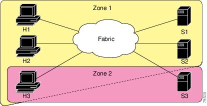
Figure 5-1 illustrates a zone set with two zones, zone 1 and zone 2, in a fabric. Zone 1 provides access from all three hosts (H1, H2, H3) to the data residing on storage systems S1 and S2. Zone 2 restricts the data on S3 to access only by H3. Note that H3 resides in both zones.
Figure 5-1 Fabric with Two Zones
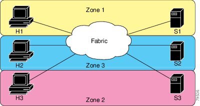
Of course, there are other ways to partition this fabric into zones. Figure 5-2 illustrates another possibility. Assume that there is a need to isolate storage system S2 for the purpose of testing new software. To achieve this, zone 3 is configured, which contains only host H2 and storage S2. You can restrict access to just H2 and S2 in zone 3, and to H1 and S1 in zone 1.
Figure 5-2 Fabric with Three Zones
Zone Implementation
All switches in the Cisco MDS 9000 Family automatically support the following basic zone features (no additional configuration is required):
•![]() Zones are contained in a VSAN.
Zones are contained in a VSAN.
•![]() Hard zoning cannot be disabled.
Hard zoning cannot be disabled.
•![]() Name server queries are soft-zoned.
Name server queries are soft-zoned.
•![]() Only active zone sets are distributed.
Only active zone sets are distributed.
•![]() Unzoned devices cannot access each other.
Unzoned devices cannot access each other.
•![]() A zone or zone set with the same name can exist in each VSAN.
A zone or zone set with the same name can exist in each VSAN.
•![]() Each VSAN has a full database and an active database.
Each VSAN has a full database and an active database.
•![]() Active zone sets cannot be changed, without activating a full zone database.
Active zone sets cannot be changed, without activating a full zone database.
•![]() Active zone sets are preserved across switch reboots.
Active zone sets are preserved across switch reboots.
•![]() Changes to the full database must be explicitly saved.
Changes to the full database must be explicitly saved.
•![]() Zone reactivation (a zone set is active and you activate another zone set) does not disrupt existing traffic.
Zone reactivation (a zone set is active and you activate another zone set) does not disrupt existing traffic.
If required, you can additionally configure the following zone features:
•![]() Propagate full zone sets to all switches on a per VSAN basis.
Propagate full zone sets to all switches on a per VSAN basis.
•![]() Change the default policy for unzoned members.
Change the default policy for unzoned members.
•![]() Interoperate with other vendors by configuring a VSAN in the interop mode. You can also configure one VSAN in the interop mode and another VSAN in the basic mode in the same switch without disrupting each other.
Interoperate with other vendors by configuring a VSAN in the interop mode. You can also configure one VSAN in the interop mode and another VSAN in the basic mode in the same switch without disrupting each other.
•![]() Bring E ports out of isolation.
Bring E ports out of isolation.
Zone Member Configuration Guidelines
All members of a zone can communicate with each other. For a zone with N members, N*(N-1) access permissions need to be enabled. The best practice is to avoid configuring large numbers of targets or large numbers of initiators in a single zone. This type of configuration wastes switch resources by provisioning and managing many communicating pairs (initiator-to-initiator or target-to-target) that will never actually communicate with each other. For this reason, a single initiator with a single target is the most efficient approach to zoning.
The following guidelines must be considered when creating zone members:
•![]() Configuring only one initiator and one target for a zone provides the most efficient use of the switch resources.
Configuring only one initiator and one target for a zone provides the most efficient use of the switch resources.
•![]() Configuring the same initiator to multiple targets is accepted.
Configuring the same initiator to multiple targets is accepted.
•![]() Configuring multiple initiators to multiple targets is not recommended.
Configuring multiple initiators to multiple targets is not recommended.
Active and Full Zone Set Considerations
Before configuring a zone set, consider the following guidelines:
•![]() Each VSAN can have multiple zone sets but only one zone set can be active at any given time.
Each VSAN can have multiple zone sets but only one zone set can be active at any given time.
•![]() When you create a zone set, that zone set becomes a part of the full zone set.
When you create a zone set, that zone set becomes a part of the full zone set.
•![]() When you activate a zone set, a copy of the zone set from the full zone set is used to enforce zoning, and is called the active zone set. An active zone set cannot be modified. A zone that is part of an active zone set is called an active zone.
When you activate a zone set, a copy of the zone set from the full zone set is used to enforce zoning, and is called the active zone set. An active zone set cannot be modified. A zone that is part of an active zone set is called an active zone.
•![]() The administrator can modify the full zone set even if a zone set with the same name is active. However, the modification will be enforced only upon reactivation.
The administrator can modify the full zone set even if a zone set with the same name is active. However, the modification will be enforced only upon reactivation.
•![]() When the activation is done, the active zone set is automatically stored in persistent configuration. This enables the switch to preserve the active zone set information across switch resets.
When the activation is done, the active zone set is automatically stored in persistent configuration. This enables the switch to preserve the active zone set information across switch resets.
•![]() All other switches in the fabric receive the active zone set so they can enforce zoning in their respective switches.
All other switches in the fabric receive the active zone set so they can enforce zoning in their respective switches.
•![]() Hard and soft zoning are implemented using the active zone set. Modifications take effect during zone set activation.
Hard and soft zoning are implemented using the active zone set. Modifications take effect during zone set activation.
•![]() An FC ID or Nx port that is not part of the active zone set belongs to the default zone and the default zone information is not distributed to other switches.
An FC ID or Nx port that is not part of the active zone set belongs to the default zone and the default zone information is not distributed to other switches.
Note ![]() If one zone set is active and you activate another zone set, the currently active zone set is automatically deactivated. You do not need to explicitly deactivate the currently active zone set before activating a new zone set.
If one zone set is active and you activate another zone set, the currently active zone set is automatically deactivated. You do not need to explicitly deactivate the currently active zone set before activating a new zone set.
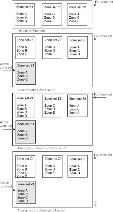
Figure 5-3 shows a zone being added to an activated zone set.
Figure 5-3 Active and Full Zone Sets
Using the Quick Config Wizard
Note ![]() The Quick Config Wizard supports only switch interface zone members.
The Quick Config Wizard supports only switch interface zone members.
As of Cisco SAN-OS Release 3.1(1) and NX-OS Release 4.1(2), you can use the Quick Config Wizard on the Cisco MDS 9124 Switch to add or remove zone members per VSAN. You can use the Quick Config Wizard to perform interface-based zoning and to assign zone members for multiple VSANs using Device Manager.
Note ![]() The Quick Config Wizard is supported on the Cisco MDS 9124 Fabric Switch, the Cisco MDS 9134 Fabric Switch, the Cisco Fabric Switch for HP c-Class BladeSystem, and the Cisco Fabric Switch for IBM BladeCenter.
The Quick Config Wizard is supported on the Cisco MDS 9124 Fabric Switch, the Cisco MDS 9134 Fabric Switch, the Cisco Fabric Switch for HP c-Class BladeSystem, and the Cisco Fabric Switch for IBM BladeCenter.

To add or remove ports from a zone and to zone only the devices within a specific VSAN using Device Manager on the Cisco MDS 9124 Switch, follow these steps:
Step 1 ![]() Choose FC > Quick Config or click the Zone icon in the toolbar.
Choose FC > Quick Config or click the Zone icon in the toolbar.
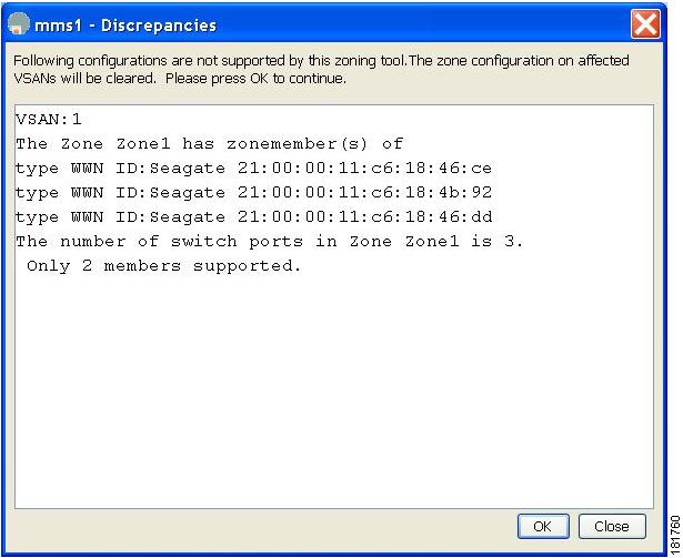
You see the Quick Config Wizard (see Figure 5-5) with all controls disabled and the Discrepancies dialog box (see Figure 5-4), which shows all unsupported configurations.
Note ![]() You will see the Discrepancies dialog box only if there are any discrepancies.
You will see the Discrepancies dialog box only if there are any discrepancies.
Figure 5-4 Discrepancies Dialog Box
Step 2 ![]() Click OK to continue.
Click OK to continue.
You see the Quick Config Wizard dialog box shown in Figure 5-5.
Caution
Figure 5-5 Quick Config Wizard
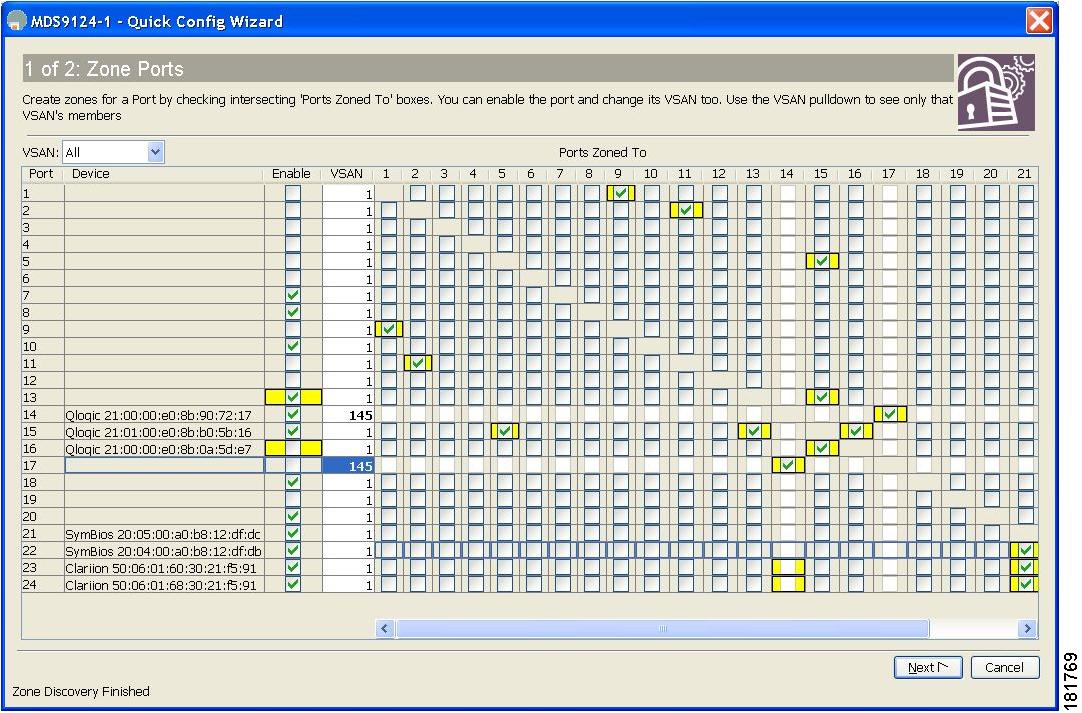
Step 3 ![]() Check the check box in the Ports Zoned To column for the port you want to add or remove from a zone. The check box for the matching port is similarly set. The selected port pair is added or removed from the zone, creating a two-device zone.
Check the check box in the Ports Zoned To column for the port you want to add or remove from a zone. The check box for the matching port is similarly set. The selected port pair is added or removed from the zone, creating a two-device zone.
The VSAN drop-down menu provides a filter that enables you to zone only those devices within a selected VSAN.
Step 4 ![]() Right-click any of the column names to show or hide a column.
Right-click any of the column names to show or hide a column.
Step 5 ![]() Click Next to verify the changes.
Click Next to verify the changes.
You see the Confirm Changes dialog box shown in Figure 5-6.
Figure 5-6 Confirm Changes Dialog Box
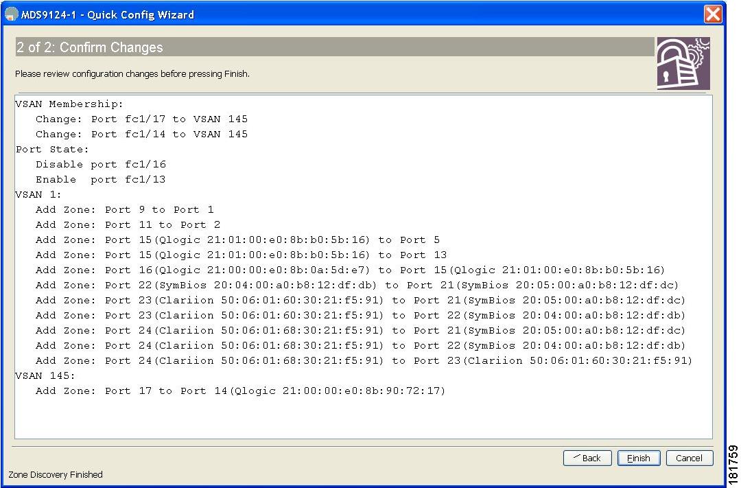
Step 6 ![]() If you want to see the CLI commands, right-click in the dialog box and click CLI Commands from the pop-up menu.
If you want to see the CLI commands, right-click in the dialog box and click CLI Commands from the pop-up menu.
Step 7 ![]() Click Finish to save the configuration changes.
Click Finish to save the configuration changes.
Zone Configuration
This section describes how to configure zones and includes the following topics:
•![]() About the Edit Local Full Zone Database Tool
About the Edit Local Full Zone Database Tool
•![]() Configuring a Zone Using the Zone Configuration Tool
Configuring a Zone Using the Zone Configuration Tool
About the Edit Local Full Zone Database Tool
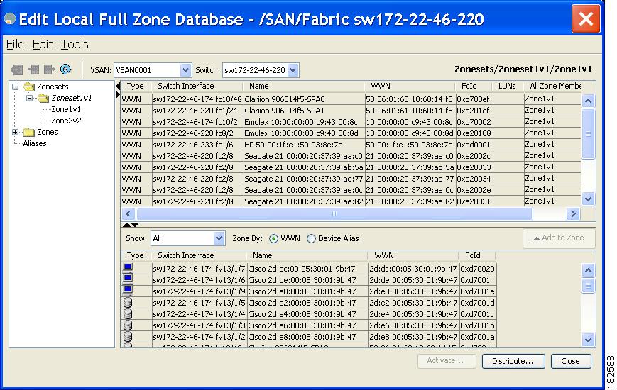
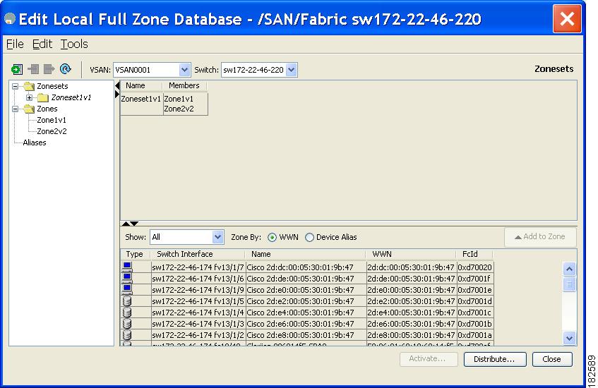
The Edit Local Full Zone Database tool allows you to zone across multiple switches and all zoning features are available through the Edit Local Full Zone Database dialog box (see Figure 5-7).
Figure 5-7 Edit Local Full Zone Database Dialog Box

Note ![]() The Device Alias radio button is visible only if device alias is in enhanced mode. For more information, see "Creating a Device Alias" section on page 6-6.
The Device Alias radio button is visible only if device alias is in enhanced mode. For more information, see "Creating a Device Alias" section on page 6-6.

Tip ![]() Expand Switches from the Physical Attributes pane to retrieve the sWWN. If you do not provide a sWWN, the software automatically uses the local sWWN.
Expand Switches from the Physical Attributes pane to retrieve the sWWN. If you do not provide a sWWN, the software automatically uses the local sWWN.
Note ![]() Interface-based zoning only works with Cisco MDS 9000 Family switches. Interface-based zoning does not work if interop mode is configured in that VSAN.
Interface-based zoning only works with Cisco MDS 9000 Family switches. Interface-based zoning does not work if interop mode is configured in that VSAN.
Configuring a Zone Using the Zone Configuration Tool
To create a zone and move it into a zone set using Fabric Manager, follow these steps:
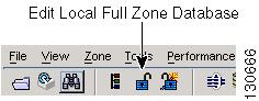
Step 1 ![]() Click the Zone icon in the toolbar (See Figure 5-8).
Click the Zone icon in the toolbar (See Figure 5-8).
Figure 5-8 Zone Icon
You see the Select VSAN dialog box.
Step 2 ![]() Select the VSAN where you want to create a zone and click OK.
Select the VSAN where you want to create a zone and click OK.
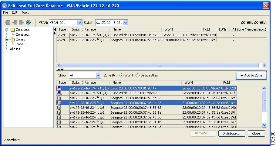
You see the Edit Local Full Zone Database dialog box shown in Figure 5-9.
Figure 5-9 Edit Local Full Zone Database Dialog Box
If you want to view zone membership information, right-click in the All Zone Membership(s) column, and then click Show Details for the current row or all rows from the pop-up menu.
Step 3 ![]() Click Zones in the left pane and click the Insert icon to create a zone.
Click Zones in the left pane and click the Insert icon to create a zone.
You see the Create Zone dialog box shown in Figure 5-10.
Figure 5-10 Create Zone Dialog Box
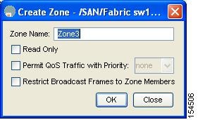
Step 4 ![]() Enter a zone name.
Enter a zone name.
Step 5 ![]() Check one of the following check boxes:
Check one of the following check boxes:
a. ![]() Read Only—The zone permits read and denies write.
Read Only—The zone permits read and denies write.
b. ![]() Permit QoS traffic with Priority—You set the priority from the drop-down menu.
Permit QoS traffic with Priority—You set the priority from the drop-down menu.
c. ![]() Restrict Broadcast Frames to Zone Members
Restrict Broadcast Frames to Zone Members
Step 6 ![]() Click OK to create the zone.
Click OK to create the zone.
If you want to move this zone into an existing zone set, skip to Step 8.
Step 7 ![]() Click Zoneset in the left pane and click the Insert icon to create a zone set.
Click Zoneset in the left pane and click the Insert icon to create a zone set.
You see the Zoneset Name dialog box shown in Figure 5-11.
Figure 5-11 Zoneset Name Dialog Box
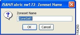
Step 8 ![]() Enter a zone set name and click OK.
Enter a zone set name and click OK.
Note ![]() One of these symbols ($, -, ^, _) or all alphanumeric characters are supported. In interop mode 2 and 3, this symbol (_) or all alphanumeric characters are supported.
One of these symbols ($, -, ^, _) or all alphanumeric characters are supported. In interop mode 2 and 3, this symbol (_) or all alphanumeric characters are supported.
Step 9 ![]() Select the zone set where you want to add a zone and click the Insert icon or you can drag and drop Zone3 over Zoneset1.
Select the zone set where you want to add a zone and click the Insert icon or you can drag and drop Zone3 over Zoneset1.
You see the Select Zone dialog box shown in Figure 5-12.
Figure 5-12 Select Zone Dialog Box
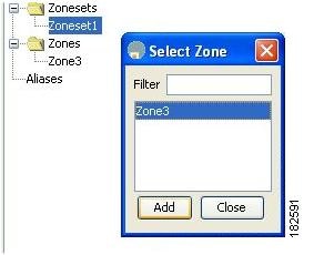
Step 10 ![]() Click Add to add the zone.
Click Add to add the zone.
Adding Zone Members
Once you create a zone, you can add members to the zone. You can add members using multiple port identification types.
To add a member to a zone using Fabric Manager, follow these steps:
Step 1 ![]() Choose Zone > Edit Local Full Zone Database.
Choose Zone > Edit Local Full Zone Database.
You see the Select VSAN dialog box.
Step 2 ![]() Select a VSAN and click OK.
Select a VSAN and click OK.
You see the Edit Local Full Zone Database dialog box for the selected VSAN.
Figure 5-13 Edit Local Full Zone Database Dialog Box
Step 3 ![]() Select the members you want to add from the Fabric pane (see Figure 5-13) and click Add to Zone or click the zone where you want to add members and click the Insert icon.
Select the members you want to add from the Fabric pane (see Figure 5-13) and click Add to Zone or click the zone where you want to add members and click the Insert icon.
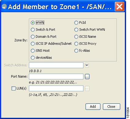
You see the Add Member to Zone dialog box shown in Figure 5-14.
Figure 5-14 Add Member to Zone Dialog Box
Note ![]() The Device Alias radio button is visible only if device alias is in enhanced mode. For more information, see "Creating a Device Alias" section on page 6-6.
The Device Alias radio button is visible only if device alias is in enhanced mode. For more information, see "Creating a Device Alias" section on page 6-6.
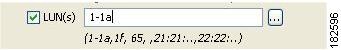
Step 4 ![]() Click the browse button and select a port name or check the LUN check box and click the browse button to configure LUNs.
Click the browse button and select a port name or check the LUN check box and click the browse button to configure LUNs.
Step 5 ![]() Click Add to add the member to the zone.
Click Add to add the member to the zone.
Note ![]() When configuring a zone member, you can specify that a single LUN has multiple IDs depending on the operating system. You can select from six different operating systems.
When configuring a zone member, you can specify that a single LUN has multiple IDs depending on the operating system. You can select from six different operating systems.
Filtering End Devices Based on Name, WWN or FC ID
To filter the end devices and device aliases, follow these steps:
Step 1 ![]() Click the Zone icon in the toolbar (See Figure 5-8).
Click the Zone icon in the toolbar (See Figure 5-8).
Step 2 ![]() Select Name, WWN or FC ID from the With drop-down list.
Select Name, WWN or FC ID from the With drop-down list.
Step 3 ![]() Enter a filter condition, such as *zo1*, in the Filter text box.
Enter a filter condition, such as *zo1*, in the Filter text box.
Step 4 ![]() Click Go.
Click Go.
Adding Multiple End Devices to Multiple Zones
To add multiple end devices to multiple zones, follow these steps:
Step 1 ![]() Click the Zone icon in the toolbar (See Figure 5-8).
Click the Zone icon in the toolbar (See Figure 5-8).
Step 2 ![]() Use the Ctrl key to select multiple end devices.
Use the Ctrl key to select multiple end devices.
Step 3 ![]() Right-click and then select Add to Zone.
Right-click and then select Add to Zone.
Step 4 ![]() Use the Ctrl key to select multiple zones from the pop-up window displayed.
Use the Ctrl key to select multiple zones from the pop-up window displayed.
Step 5 ![]() Click Add.
Click Add.
Selected end devices are added to the selected zones.
Zone Sets
Zones provide a mechanism for specifying access control, while zone sets are a grouping of zones to enforce access control in the fabric.
This section describes zone sets and includes the following topics:
•![]() Displaying Zone Membership Information
Displaying Zone Membership Information
•![]() Converting Zone Members to pWWN-based Members
Converting Zone Members to pWWN-based Members
About Zone Set Creation
In Figure 5-15, two separate sets are created, each with its own membership hierarchy and zone members.
Figure 5-15 Hierarchy of Zone Sets, Zones, and Zone Members
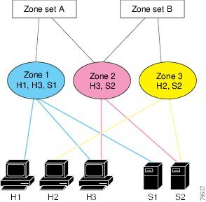
Either zone set A or zone set B can be activated (but not together).
Tip ![]() Zone sets are configured with the names of the member zones and the VSAN (if the zone set is in a configured VSAN).
Zone sets are configured with the names of the member zones and the VSAN (if the zone set is in a configured VSAN).
Activating a Zone Set
Changes to a zone set do not take effect in a full zone set until you activate it.
To activate an existing zone set using Fabric Manager, follow these steps:
Step 1 ![]() Choose Zone > Edit Local Full Zone Database.
Choose Zone > Edit Local Full Zone Database.
You see the Select VSAN dialog box.
Step 2 ![]() Select a VSAN and click OK.
Select a VSAN and click OK.
You see the Edit Local Full Zone Database dialog box for the selected VSAN.
Step 3 ![]() Click Activate to activate the zone set.
Click Activate to activate the zone set.
You see the pre-activation check dialog box shown in Figure 5-16.
Figure 5-16 Pre-Activation Check Dialog Box
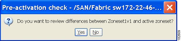
Step 4 ![]() Click Yes to review the differences.
Click Yes to review the differences.
You see the Local vs. Active Differences dialog box shown in Figure 5-17.
Figure 5-17 Local vs Active Differences Dialog Box
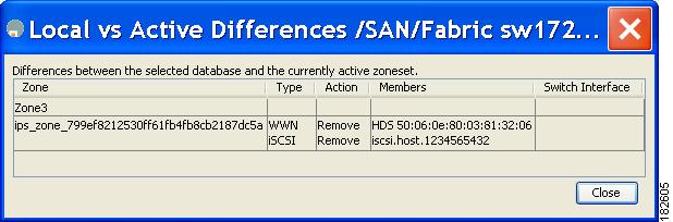
Step 5 ![]() Click Close to close the dialog box.
Click Close to close the dialog box.
You see the Save Configuration dialog box shown in Figure 5-18.
Figure 5-18 Save Configuration Dialog Box
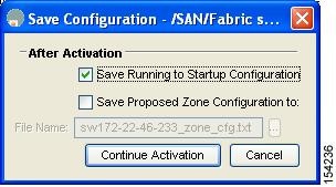
Step 6 ![]() Check the Save Running to Startup Configuration check box to save all changes to the startup configuration.
Check the Save Running to Startup Configuration check box to save all changes to the startup configuration.
Step 7 ![]() Click Continue Activation to activate the zone set, or click Cancel to close the dialog box and discard any unsaved changes.
Click Continue Activation to activate the zone set, or click Cancel to close the dialog box and discard any unsaved changes.
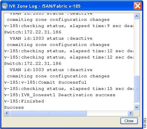
You see the Zone Log dialog box, which shows if the zone set activation was successful (see Figure 5-19).
Figure 5-19 Zone Log Dialog Box
Deactivating a Zoneset
To deactivate an existing zone set, follow these steps:
Step 1 ![]() Right-click the zone set you want to deactivate and then click Deactivate from the pop-up menu.
Right-click the zone set you want to deactivate and then click Deactivate from the pop-up menu.
You see the Deactivate Zoneset dialog box as shown in Figure 5-20.
Figure 5-20
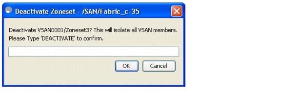
Deactivate Zoneset Dialog Box
Step 2 ![]() Enter deactivate in the text box and then click OK.
Enter deactivate in the text box and then click OK.
You see the Input dialog box as shown in Figure 5-21.
Figure 5-21
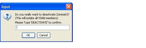
Input Dialog Box
Step 3 ![]() Enter deactivate in the text box and then click OK to deactivate the zone set.
Enter deactivate in the text box and then click OK to deactivate the zone set.
Note ![]() To enable this option, you need to modify the server.properties file. Refer to the Cisco Fabric Manager Fundamentals Configuration Guide to know more about modifying server.properties file.
To enable this option, you need to modify the server.properties file. Refer to the Cisco Fabric Manager Fundamentals Configuration Guide to know more about modifying server.properties file.
Displaying Zone Membership Information
To display zone membership information for members assigned to zones in Fabric Manager, follow these steps:
Step 1 ![]() Choose Zone > Edit Local Full Zone Database.
Choose Zone > Edit Local Full Zone Database.
You see the Select VSAN dialog box.
Step 2 ![]() Select a VSAN and click OK.
Select a VSAN and click OK.
You see the Edit Local Full Zone Database dialog box for the selected VSAN.
Step 3 ![]() Click Zones in the left pane. The right pane lists the members for each zone.
Click Zones in the left pane. The right pane lists the members for each zone.
Note ![]() The default zone members are explicitly listed only when the default zone policy is configured as permit. When the default zone policy is configured as deny, the members of this zone are not shown. See the "Displaying Zone Information" section.
The default zone members are explicitly listed only when the default zone policy is configured as permit. When the default zone policy is configured as deny, the members of this zone are not shown. See the "Displaying Zone Information" section.
About the Default Zone
Each member of a fabric (in effect a device attached to an Nx port) can belong to any zone. If a member is not part of any active zone, it is considered to be part of the default zone. Therefore, if no zone set is active in the fabric, all devices are considered to be in the default zone. Even though a member can belong to multiple zones, a member that is part of the default zone cannot be part of any other zone. The switch determines whether a port is a member of the default zone when the attached port comes up.
Note ![]() Unlike configured zones, default zone information is not distributed to the other switches in the fabric.
Unlike configured zones, default zone information is not distributed to the other switches in the fabric.
Traffic can either be permitted or denied among members of the default zone. This information is not distributed to all switches; it must be configured in each switch.
Note ![]() When the switch is initialized for the first time, no zones are configured and all members are considered to be part of the default zone. Members are not permitted to talk to each other.
When the switch is initialized for the first time, no zones are configured and all members are considered to be part of the default zone. Members are not permitted to talk to each other.
Configure the default zone policy on each switch in the fabric. If you change the default zone policy on one switch in a fabric, be sure to change it on all the other switches in the fabric.
Note ![]() The default settings for default zone configurations can be changed.
The default settings for default zone configurations can be changed.
The default zone members are explicitly listed when the default policy is configured as permit or when a zone set is active. When the default policy is configured as deny, the members of this zone are not explicitly enumerated when you view the active zone set.
You can change the default zone policy for any VSAN by choosing VSANxx > Default Zone from the Fabric Manager menu tree and clicking the Policies tab. It is recommended that you establish connectivity among devices by assigning them to a non-default zone.
Configuring the Default Zone
To permit or deny traffic to members in the default zone using Fabric Manager, follow these steps:
Step 1 ![]() Expand a VSAN and then select Default Zone in the Fabric Manager Logical Domains pane.
Expand a VSAN and then select Default Zone in the Fabric Manager Logical Domains pane.
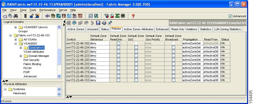
Step 2 ![]() Click the Policies tab in the Information pane.
Click the Policies tab in the Information pane.
You see the zone policies information in the Information pane (see Figure 5-22).
Figure 5-22 Default Zone Policies
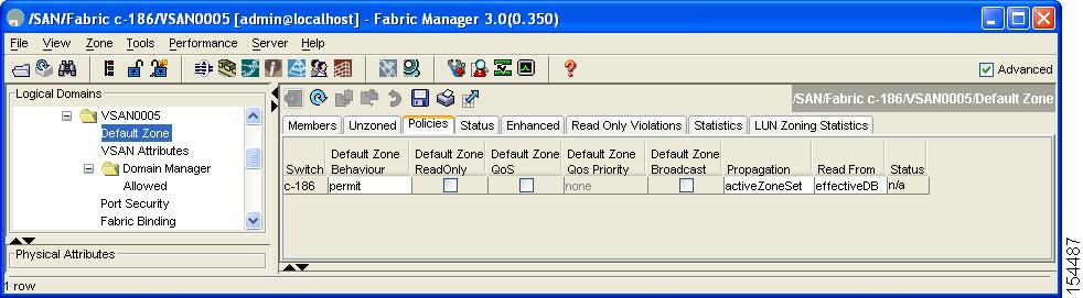
The active zone set is shown in italic type. After you make changes to the active zone set and before you activate the changes, the zone set is shown in boldface italic type.
Step 3 ![]() In the Default Zone Behaviour field, choose either permit or deny from the drop-down menu.
In the Default Zone Behaviour field, choose either permit or deny from the drop-down menu.
About FC Alias Creation
You can assign an alias name and configure an alias member using the following values:
•![]() pWWN—The WWN of the N or NL port is in hex format (for example, 10:00:00:23:45:67:89:ab).
pWWN—The WWN of the N or NL port is in hex format (for example, 10:00:00:23:45:67:89:ab).
•![]() fWWN—The WWN of the fabric port name is in hex format (for example, 10:00:00:23:45:67:89:ab).
fWWN—The WWN of the fabric port name is in hex format (for example, 10:00:00:23:45:67:89:ab).
•![]() FC ID—The N port ID is in 0xhhhhhh format (for example, 0xce00d1).
FC ID—The N port ID is in 0xhhhhhh format (for example, 0xce00d1).
•![]() Domain ID—The domain ID is an integer from 1 to 239. A mandatory port number of a non-Cisco switch is required to complete this membership configuration.
Domain ID—The domain ID is an integer from 1 to 239. A mandatory port number of a non-Cisco switch is required to complete this membership configuration.
•![]() IPv4 address—The IPv4 address of an attached device is in 32 bits in dotted decimal format along with an optional subnet mask. If a mask is specified, any device within the subnet becomes a member of the specified zone.
IPv4 address—The IPv4 address of an attached device is in 32 bits in dotted decimal format along with an optional subnet mask. If a mask is specified, any device within the subnet becomes a member of the specified zone.
•![]() IPv6 address—The IPv6 address of an attached device is in 128 bits in colon- (:) separated) hexadecimal format.
IPv6 address—The IPv6 address of an attached device is in 128 bits in colon- (:) separated) hexadecimal format.
•![]() Interface—Interface-based zoning is similar to port-based zoning because the switch interface is used to configure the zone. You can specify a switch interface as a zone member for both local and remote switches. To specify a remote switch, enter the remote switch WWN (sWWN) or the domain ID in the particular VSAN.
Interface—Interface-based zoning is similar to port-based zoning because the switch interface is used to configure the zone. You can specify a switch interface as a zone member for both local and remote switches. To specify a remote switch, enter the remote switch WWN (sWWN) or the domain ID in the particular VSAN.
Tip ![]() The Cisco NX-OS software supports a maximum of 2048 aliases per VSAN.
The Cisco NX-OS software supports a maximum of 2048 aliases per VSAN.
Creating FC Aliases
To create an FC alias using Fabric Manager, follow these steps:
Step 1 ![]() Choose Zone > Edit Local Full Zone Database.
Choose Zone > Edit Local Full Zone Database.
You see the Select VSAN dialog box.
Step 2 ![]() Select a VSAN and click OK.
Select a VSAN and click OK.
You see the Edit Local Full Zone Database dialog box for the selected VSAN.
Step 3 ![]() Click Aliases in the lower left pane (see Figure 5-23). The right pane lists the existing aliases.
Click Aliases in the lower left pane (see Figure 5-23). The right pane lists the existing aliases.
Figure 5-23 Creating an FC Alias
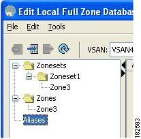
Step 4 ![]() Click the Insert icon to create an alias.
Click the Insert icon to create an alias.
You see the Create Alias dialog box shown in Figure 5-24.
Figure 5-24 Create Alias Dialog Box
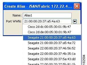
Step 5 ![]() Set the Alias Name and the pWWN.
Set the Alias Name and the pWWN.
Step 6 ![]() Click OK to create the alias.
Click OK to create the alias.
Adding Members to Aliases
To add a member to an alias using Fabric Manager, follow these steps:
Step 1 ![]() Choose Zone > Edit Local Full Zone Database.
Choose Zone > Edit Local Full Zone Database.
You see the Select VSAN dialog box.
Step 2 ![]() Select a VSAN and click OK.
Select a VSAN and click OK.
You see the Edit Local Full Zone Database dialog box for the selected VSAN as shown in Figure 5-25.
Figure 5-25 Edit Local Full Zone Database Dialog Box
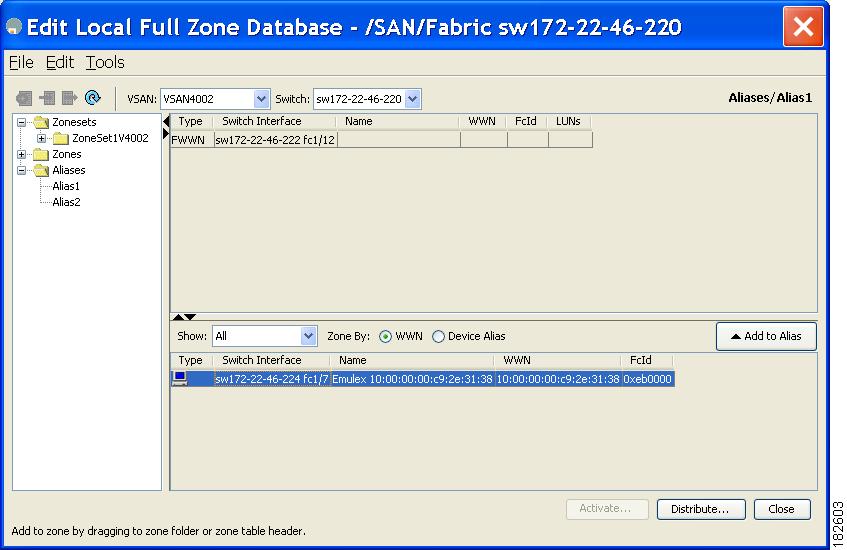
Step 3 ![]() Select the member(s) you want to add from the Fabric pane (see Figure 5-25) and click Add to Alias or click the alias where you want to add members and click the Insert icon.
Select the member(s) you want to add from the Fabric pane (see Figure 5-25) and click Add to Alias or click the alias where you want to add members and click the Insert icon.
You see the Add Member to Alias dialog box shown in Figure 5-26.
Figure 5-26 Add Member to Alias Dialog Box
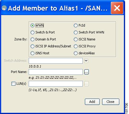
Note ![]() The Device Alias radio button is visible only if device alias is in enhanced mode. For more information, see "Creating a Device Alias" section on page 6-6.
The Device Alias radio button is visible only if device alias is in enhanced mode. For more information, see "Creating a Device Alias" section on page 6-6.
Step 4 ![]() Click the browse button and select a port name or check the LUN check box and click the browse button to configure LUNs.
Click the browse button and select a port name or check the LUN check box and click the browse button to configure LUNs.
Step 5 ![]() Click Add to add the member to the alias.
Click Add to add the member to the alias.
Converting Zone Members to pWWN-based Members
You can convert zone and alias members from switch port or FC ID based membership to pWWN-based membership. You can use this feature to convert to pWWN so that your zone configuration does not change if a card or switch is changed in your fabric.
To convert switch port and FC ID members to pWWN members using Fabric Manager, follow these steps:
Step 1 ![]() Choose Zone > Edit Local Full Zone Database.
Choose Zone > Edit Local Full Zone Database.
You see the Select VSAN dialog box.
Step 2 ![]() Select a VSAN and click OK.
Select a VSAN and click OK.
You see the Edit Local Full Zone Database dialog box for the selected VSAN.
Step 3 ![]() Click the zone you want to convert.
Click the zone you want to convert.
Step 4 ![]() Choose Tools > Convert Switch Port/FCID members to By pWWN.
Choose Tools > Convert Switch Port/FCID members to By pWWN.
You see the conversion dialog box, listing all members that will be converted.
Step 5 ![]() Verify the changes and click Continue Conversion.
Verify the changes and click Continue Conversion.
Step 6 ![]() Click Yes in the confirmation dialog box to convert that member to pWWN-based membership.
Click Yes in the confirmation dialog box to convert that member to pWWN-based membership.
Note ![]() If one zone set is active and you activate another zone set, the currently active zone set is automatically deactivated.
If one zone set is active and you activate another zone set, the currently active zone set is automatically deactivated.
Tip ![]() You do not have to copy the running configuration to the startup configuration to store the active zone set. However, you need to copy the running configuration to the startup configuration to explicitly store full zone sets. It is not available across switch resets.
You do not have to copy the running configuration to the startup configuration to store the active zone set. However, you need to copy the running configuration to the startup configuration to explicitly store full zone sets. It is not available across switch resets.
Note ![]() The pWWN of the virtual target does not appear in the zoning end devices database in Fabric Manager. If you want to zone the virtual device with a pWWN, you must enter it in the Add Member to Zone dialog box when creating a zone. However, if the device alias is in enhanced mode, the virtual device names appear in the device alias database in the Fabric Manager zoning window. In this case, users can choose to select either the device alias name or enter the pWWN in the Add Member to Zone dialog box.
The pWWN of the virtual target does not appear in the zoning end devices database in Fabric Manager. If you want to zone the virtual device with a pWWN, you must enter it in the Add Member to Zone dialog box when creating a zone. However, if the device alias is in enhanced mode, the virtual device names appear in the device alias database in the Fabric Manager zoning window. In this case, users can choose to select either the device alias name or enter the pWWN in the Add Member to Zone dialog box.
For more information, see the "Adding Zone Members" section.
Note ![]() Set the device alias mode to enhanced when using SDV (because the pWWN of a virtual device could change).
Set the device alias mode to enhanced when using SDV (because the pWWN of a virtual device could change).
For example, SDV is enabled on a switch and a virtual device is defined. SDV assigns a pWWN for the virtual device, and it is zoned based on the pWWN in a zone. If you later disable SDV, this configuration is lost. If you reenable SDV and create the virtual device using the same name, there is no guarantee that it will get the same pWWN again. Hence, you would have to rezone the pWWN-based zone. However, if you perform zoning based on the device-alias name, there are no configuration changes required if or when the pWWN changes.
Be sure you understand how device alias modes work before enabling them. Refer to Chapter 6, "Distributing Device Alias Services" for details and requirements about device alias modes.
Filtering Zones, Zone Sets, and Device Aliases Based on Name
To filter the zones, zone sets or device aliases, follow these steps:
Step 1 ![]() Click the Zone icon in the toolbar (See Figure 5-8).
Click the Zone icon in the toolbar (See Figure 5-8).
Step 2 ![]() Enter a filter condition, such as *zo1*, in the Filter text box.
Enter a filter condition, such as *zo1*, in the Filter text box.
Step 3 ![]() Click Go.
Click Go.
Adding Multiple Zones to Multiple Zone Sets
To add multiple zones to multiple zone sets, follow these steps:
Step 1 ![]() Click the Zone icon in the toolbar (See Figure 5-8).
Click the Zone icon in the toolbar (See Figure 5-8).
Step 2 ![]() From the tree view, select Zoneset .
From the tree view, select Zoneset .
Step 3 ![]() Use the Ctrl key to select multiple zones.
Use the Ctrl key to select multiple zones.
Step 4 ![]() Right-click and then select Add to Zoneset.
Right-click and then select Add to Zoneset.
Step 5 ![]() Use the Ctrl key to select multiple zone sets from the pop-up window displayed.
Use the Ctrl key to select multiple zone sets from the pop-up window displayed.
Step 6 ![]() Click Add.
Click Add.
Selected zones are added to the selected zone sets.
Zone Enforcement
Zoning can be enforced in two ways: soft and hard. Each end device (N port or NL port) discovers other devices in the fabric by querying the name server. When a device logs in to the name server, the name server returns the list of other devices that can be accessed by the querying device. If an Nx port does not know about the FC IDs of other devices outside its zone, it cannot access those devices.
In soft zoning, zoning restrictions are applied only during interaction between the name server and the end device. If an end device somehow knows the FC ID of a device outside its zone, it can access that device.
Hard zoning is enforced by the hardware on each frame sent by an Nx port. As frames enter the switch, source-destination IDs are compared with permitted combinations to allow the frame at wirespeed. Hard zoning is applied to all forms of zoning.
Note ![]() Hard zoning enforces zoning restrictions on every frame, and prevents unauthorized access.
Hard zoning enforces zoning restrictions on every frame, and prevents unauthorized access.
Switches in the Cisco MDS 9000 Family support both hard and soft zoning.
Zone Set Distribution
You can distribute full zone sets using one of two methods: one-time distribution or full zone set distribution. Table 5-1 lists the differences between these distribution methods.
This section describes zone set distribution and includes the following topics:
•![]() Enabling Full Zone Set Distribution
Enabling Full Zone Set Distribution
•![]() Enabling a One-Time Distribution
Enabling a One-Time Distribution
•![]() About Recovering from Link Isolation
About Recovering from Link Isolation
•![]() Importing and Exporting Zone Sets
Importing and Exporting Zone Sets
Enabling Full Zone Set Distribution
All switches in the Cisco MDS 9000 Family distribute active zone sets when new E port links come up or when a new zone set is activated in a VSAN. The zone set distribution takes effect while sending merge requests to the adjacent switch or while activating a zone set.
To enable full zone set and active zone set distribution to all switches on a per VSAN basis using Fabric Manager, follow these steps:
Step 1 ![]() Expand a VSAN and select a zone set in the Logical Domains pane.
Expand a VSAN and select a zone set in the Logical Domains pane.
You see the zone set configuration in the Information pane. The Active Zones tab is the default.
Step 2 ![]() Click the Policies tab.
Click the Policies tab.
You see the configured policies for the zone (see Figure 5-27).
Figure 5-27 Configured Policies for the Zone
Step 3 ![]() In the Propagation column, choose fullZoneset from the drop-down menu.
In the Propagation column, choose fullZoneset from the drop-down menu.
Step 4 ![]() Click Apply Changes to propagate the full zone set.
Click Apply Changes to propagate the full zone set.
Enabling a One-Time Distribution
You can perform a one-time distribution of inactive, unmodified zone sets throughout the fabric. To propagate a one-time distribution of the full zone set using Fabric Manager, follow these steps:
Step 1 ![]() Choose Zone > Edit Local Full Zone Database.
Choose Zone > Edit Local Full Zone Database.
You see the Edit Local Full Zone Database dialog box.
Step 2 ![]() Click the appropriate zone from the list in the left pane.
Click the appropriate zone from the list in the left pane.
Step 3 ![]() Click Distribute to distribute the full zone set across the fabric.
Click Distribute to distribute the full zone set across the fabric.
This procedure only distributes the full zone set information; it does not save the information to the startup configuration. You must explicitly save the running configuration to the startup configuration issue the to save the full zone set information to the startup configuration.
Note ![]() The one-time distribution of the full zone set is supported in interop 2 and interop 3 modes, not in interop 1 mode.
The one-time distribution of the full zone set is supported in interop 2 and interop 3 modes, not in interop 1 mode.
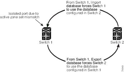
About Recovering from Link Isolation
When two switches in a fabric are merged using a TE or E port, these TE and E ports may become isolated when the active zone set databases are different between the two switches or fabrics. When a TE port or an E port become isolated, you can recover that port from its isolated state using one of three options:
•![]() Import the neighboring switch's active zone set database and replace the current active zone set (see Figure 5-28).
Import the neighboring switch's active zone set database and replace the current active zone set (see Figure 5-28).
•![]() Export the current database to the neighboring switch.
Export the current database to the neighboring switch.
•![]() Manually resolve the conflict by editing the full zone set, activating the corrected zone set, and then bringing up the link.
Manually resolve the conflict by editing the full zone set, activating the corrected zone set, and then bringing up the link.
Figure 5-28 Importing and Exporting the Database
Importing and Exporting Zone Sets
To import or export the zone set information from or to an adjacent switch using Fabric Manager, follow these steps:
Step 1 ![]() Choose Tools > Zone Merge Fail Recovery.
Choose Tools > Zone Merge Fail Recovery.
You see the Zone Merge Failure Recovery dialog box shown in Figure 5-29.
Figure 5-29 Zone Merge Failure Recovery Dialog Box
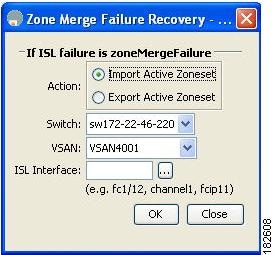
Step 2 ![]() Click the Import Active Zoneset or the Export Active Zoneset radio button.
Click the Import Active Zoneset or the Export Active Zoneset radio button.
Step 3 ![]() Select the switch from which to import or export the zone set information from the drop-down list.
Select the switch from which to import or export the zone set information from the drop-down list.
Step 4 ![]() Select the VSAN from which to import or export the zone set information from the drop-down list.
Select the VSAN from which to import or export the zone set information from the drop-down list.
Step 5 ![]() Select the interface to use for the import process.
Select the interface to use for the import process.
Step 6 ![]() Click OK to import or export the active zone set.
Click OK to import or export the active zone set.
Note ![]() Issue the import and export from a single switch. Importing from one switch and exporting from another switch can lead to isolation again.
Issue the import and export from a single switch. Importing from one switch and exporting from another switch can lead to isolation again.
Zone Set Duplication
You can make a copy and then edit it without altering the existing active zone set. You can copy an active zone set from the bootflash: directory, volatile: directory, or slot0, to one of the following areas:
•![]() To the full zone set
To the full zone set
•![]() To a remote location (using FTP, SCP, SFTP, or TFTP)
To a remote location (using FTP, SCP, SFTP, or TFTP)
The active zone set is not part of the full zone set. You cannot make changes to an existing zone set and activate it, if the full zone set is lost or is not propagated.
This section includes the following topics:
•![]() About Backing Up and Restoring Zones
About Backing Up and Restoring Zones
•![]() Renaming Zones, Zone Sets, and Aliases
Renaming Zones, Zone Sets, and Aliases
•![]() Cloning Zones, Zone Sets, FC Aliases, and Zone Attribute Groups
Cloning Zones, Zone Sets, FC Aliases, and Zone Attribute Groups
•![]() Clearing the Zone Server Database
Clearing the Zone Server Database
Copying Zone Sets
On the Cisco MDS Family switches, you cannot edit an active zone set. However, you can copy an active zone set to create a new zone set that you can edit.
To make a copy of a zone set using Fabric Manager, follow these steps:
Step 1 ![]() Choose Edit > Copy Full Zone Database.
Choose Edit > Copy Full Zone Database.
You see the Copy Full Zone Database dialog box (Figure 5-30).
Figure 5-30 Copy Full Zone Database Dialog Box
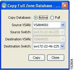
Step 2 ![]() Click the Active or the Full radio button, depending on which type of database you want to copy.
Click the Active or the Full radio button, depending on which type of database you want to copy.
Step 3 ![]() Select the source VSAN from the drop-down list.
Select the source VSAN from the drop-down list.
Step 4 ![]() If you selected Copy Full, select the source switch and the destination VSAN from those drop-down lists.
If you selected Copy Full, select the source switch and the destination VSAN from those drop-down lists.
Step 5 ![]() Select the destination switch from the drop-down list.
Select the destination switch from the drop-down list.
Step 6 ![]() Click Copy to copy the database.
Click Copy to copy the database.
About Backing Up and Restoring Zones
You can back up the zone configuration to a workstation using TFTP. This zone backup file can then be used to restore the zone configuration on a switch. Restoring the zone configuration overwrites any existing zone configuration on a switch.
Backing Up Zones
To back up the full zone configuration using Fabric Manager, follow these steps:
Step 1 ![]() Choose Zone > Edit Local Full Zone Database.
Choose Zone > Edit Local Full Zone Database.
You see the Select VSAN dialog box.
Step 2 ![]() Select a VSAN and click OK.
Select a VSAN and click OK.
You see the Edit Local Full Zone Database dialog box for the selected VSAN as shown in Figure 5-31.
Figure 5-31
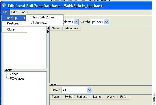
Edit Local Full Zone Database
Step 3 ![]() Choose File > Backup > This VSAN Zones to back up the existing zone configuration to a workstation using TFTP, SFTP, SCP, or FTP.
Choose File > Backup > This VSAN Zones to back up the existing zone configuration to a workstation using TFTP, SFTP, SCP, or FTP.
You see the Backup Zone Configuration dialog box shown in Figure 5-32.
Figure 5-32 Backup Zone Configuration Dialog Box
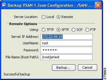
You can edit this configuration before backing up the data to a remote server.
Step 4 ![]() Provide the following Remote Options information to back up data onto a remote server:
Provide the following Remote Options information to back up data onto a remote server:
a. ![]() Using—Select the protocol.
Using—Select the protocol.
b. ![]() Server IP Address—Enter the IP adress of the server.
Server IP Address—Enter the IP adress of the server.
c. ![]() UserName—Enter the name of the user.
UserName—Enter the name of the user.
d. ![]() Password—Enter the password for the user.
Password—Enter the password for the user.
e. ![]() File Name(Root Path)—Enter the path and the filename.
File Name(Root Path)—Enter the path and the filename.
Step 5 ![]() Click Backup or click Cancel to close the dialog box without backing up.
Click Backup or click Cancel to close the dialog box without backing up.
Restoring Zones
To restore the full zone configuration using Fabric Manager, follow these steps:
Step 1 ![]() Choose Zone > Edit Local Full Zone Database.
Choose Zone > Edit Local Full Zone Database.
You see the Select VSAN dialog box.
Step 2 ![]() Select a VSAN and click OK.
Select a VSAN and click OK.
You see the Edit Local Full Zone Database dialog box for the selected VSAN as shown in Figure 5-33.
Figure 5-33
Edit Local Full Zone Database
Step 3 ![]() Choose File > Restore to restore a saved zone configuration using TFTP, SFTP, SCP or FTP.
Choose File > Restore to restore a saved zone configuration using TFTP, SFTP, SCP or FTP.
You see the Restore Zone Configuration dialog box shown in Figure 5-34.
Figure 5-34 Restore Zone Configuration Dialog Box
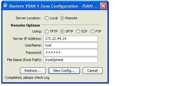
You can edit this configuration before restoring it to the switch.
Step 4 ![]() Provide the following Remote Options information to restore data from a remote server:
Provide the following Remote Options information to restore data from a remote server:
a. ![]() Using—Select the protocol.
Using—Select the protocol.
b. ![]() Server IP Address—Enter the IP address of the server.
Server IP Address—Enter the IP address of the server.
c. ![]() UserName—Enter the name of the user.
UserName—Enter the name of the user.
d. ![]() Password—Enter the password for the user.
Password—Enter the password for the user.
e. ![]() File Name—Enter the path and the filename.
File Name—Enter the path and the filename.
Step 5 ![]() Click Restore to continue or click Cancel to close the dialog box without restoring.
Click Restore to continue or click Cancel to close the dialog box without restoring.
Note ![]() Click View Config to see information on how the zone configuration file from a remote server will be restored. When you click Yes in this dialog box, you will be presented with the CLI commands that are executed. To close the dialog box, click Close.
Click View Config to see information on how the zone configuration file from a remote server will be restored. When you click Yes in this dialog box, you will be presented with the CLI commands that are executed. To close the dialog box, click Close.
Note ![]() Backup and Restore options are available to switches that run Cisco NX-OS Release 4.1(3) or later.
Backup and Restore options are available to switches that run Cisco NX-OS Release 4.1(3) or later.
Renaming Zones, Zone Sets, and Aliases
To rename a zone, zone set, or alias using Fabric Manager, follow these steps:
Step 1 ![]() Choose Zone > Edit Local Full Zone Database.
Choose Zone > Edit Local Full Zone Database.
You see the Select VSAN dialog box.
Step 2 ![]() Select a VSAN and click OK.
Select a VSAN and click OK.
You see the Edit Local Full Zone Database dialog box for the selected VSAN (see Figure 5-35).
Figure 5-35 Edit Local Full Zone Database Dialog Box
Step 3 ![]() Click a zone or zone set in the left pane.
Click a zone or zone set in the left pane.
Step 4 ![]() Choose Edit > Rename.
Choose Edit > Rename.
An edit box appears around the zone or zone set name.
Step 5 ![]() Enter a new name.
Enter a new name.
Step 6 ![]() Click Activate or Distribute.
Click Activate or Distribute.
Cloning Zones, Zone Sets, FC Aliases, and Zone Attribute Groups
To clone a zone, zone set, fcalias, or zone attribute group, follow these steps:
Step 1 ![]() Choose Zone > Edit Local Full Zone Database.
Choose Zone > Edit Local Full Zone Database.
You see the Select VSAN dialog box.
Step 2 ![]() Select a VSAN and click OK.
Select a VSAN and click OK.
You see the Edit Local Full Zone Database dialog box for the selected VSAN.
Step 3 ![]() Choose Edit > Clone.
Choose Edit > Clone.
You see the Clone Zoneset dialog box shown in Figure 5-36. The default name is the word Clone followed by the original name.
Figure 5-36 Clone Zoneset Dialog Box
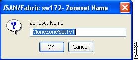
Step 4 ![]() Change the name for the cloned entry.
Change the name for the cloned entry.
Step 5 ![]() Click OK to save the new clone.
Click OK to save the new clone.
The cloned database now appears along with the original database.
Migrating a Non-MDS Database
To use the Zone Migration Wizard to migrate a non-MDS database using Fabric Manager, follow these steps:
Step 1 ![]() Choose Zone > Migrate Non-MDS Database.
Choose Zone > Migrate Non-MDS Database.
You see the Zone Migration Wizard.
Step 2 ![]() Follow the prompts in the wizard to migrate the database.
Follow the prompts in the wizard to migrate the database.
Clearing the Zone Server Database
You can clear all configured information in the zone server database for the specified VSAN.To clear the zone server database, refer to the Cisco MDS 9000 Family CLI Configuration Guide.
Note ![]() Clearing a zone set only erases the full zone database, not the active zone database.
Clearing a zone set only erases the full zone database, not the active zone database.
Note ![]() After clearing the zone server database, you must explicitly copy the running configuration to the startup configuration to ensure that the running configuration is used when the switch reboots.
After clearing the zone server database, you must explicitly copy the running configuration to the startup configuration to ensure that the running configuration is used when the switch reboots.
Advanced Zone Attributes
This section describes advanced zone attributes and includes the following topics:
•![]() About Zone-Based Traffic Priority
About Zone-Based Traffic Priority
•![]() Configuring Zone-Based Traffic Priority
Configuring Zone-Based Traffic Priority
•![]() Configuring Default Zone QoS Priority Attributes
Configuring Default Zone QoS Priority Attributes
•![]() Configuring the Default Zone Policy
Configuring the Default Zone Policy
•![]() Assigning LUNs to Storage Subsystems
Assigning LUNs to Storage Subsystems
About Zone-Based Traffic Priority
The zoning feature provides an additional segregation mechanism to prioritize select zones in a fabric and set up access control between devices. Using this feature, you can configure the quality of service (QoS) priority as a zone attribute. You can assign the QoS traffic priority attribute to be high, medium, or low. By default, zones with no specified priority are implicitly assigned a low priority. Refer to the Cisco MDS 9000 NX-OS Family Quality of Service Configuration Guide for more information.
To use this feature, you need to obtain the ENTERPRISE_PKG license (refer tothe Cisco NX-OS Family Licensing Guide) and you must enable QoS in the switch (refer to the Cisco MDS 9000 Family NX-OS Quality of Service Configuration Guide).
This feature allows SAN administrators to configure QoS in terms of a familiar data flow identification paradigm. You can configure this attribute on a zone-wide basis rather than between zone members.
Configuring Zone-Based Traffic Priority
To configure the zone priority using Fabric Manager, follow these steps:
Step 1 ![]() Expand a VSAN and then select a zone set in the Logical Domains pane.
Expand a VSAN and then select a zone set in the Logical Domains pane.
Step 2 ![]() Click the Policies tab in the Information pane.
Click the Policies tab in the Information pane.
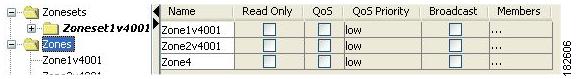
You see the Zone policy information in the Information pane (see Figure 5-37).
Figure 5-37 Zone Policies Tab in the Information Pane
Step 3 ![]() Use the check boxes and drop-down menus to configure QoS on the default zone.
Use the check boxes and drop-down menus to configure QoS on the default zone.
Step 4 ![]() Click Apply Changes to save the changes.
Click Apply Changes to save the changes.
Configuring Default Zone QoS Priority Attributes
QoS priority attribute configuration changes take effect when you activate the zone set of the associated zone.
Note ![]() If a member is part of two zones with two different QoS priority attributes, the higher QoS value is implemented. This situation does not arise in the VSAN-based QoS as the first matching entry is implemented.
If a member is part of two zones with two different QoS priority attributes, the higher QoS value is implemented. This situation does not arise in the VSAN-based QoS as the first matching entry is implemented.
To configure the QoS priority attributes for a default zone using Fabric Manager, follow these steps:
Step 1 ![]() Choose Zone > Edit Local Full Zone Database.
Choose Zone > Edit Local Full Zone Database.
You see the Select VSAN dialog box.
Step 2 ![]() Select a VSAN and click OK.
Select a VSAN and click OK.
You see the Edit Local Full Zone Database dialog box for the selected VSAN.
Step 3 ![]() Choose Edit > Edit Default Zone Attributes to configure the default zone QoS priority attributes (see Figure 5-38).
Choose Edit > Edit Default Zone Attributes to configure the default zone QoS priority attributes (see Figure 5-38).
Figure 5-38 QoS Priority Attributes
Step 4 ![]() Check the Permit QoS Traffic with Priority check box and set the Qos Priority drop-down menu to low, medium, or high.
Check the Permit QoS Traffic with Priority check box and set the Qos Priority drop-down menu to low, medium, or high.
Step 5 ![]() Click OK to save these changes.
Click OK to save these changes.
Configuring the Default Zone Policy
To permit or deny traffic in the default zone using Fabric Manager, follow these steps:
Step 1 ![]() Choose Zone > Edit Local Full Zone Database.
Choose Zone > Edit Local Full Zone Database.
You see the Select VSAN dialog box.
Step 2 ![]() Select a VSAN and click OK.
Select a VSAN and click OK.
You see the Edit Local Full Zone Database dialog box for the selected VSAN.
Step 3 ![]() Choose Edit > Edit Default Zone Attributes to configure the default zone QoS priority attributes.
Choose Edit > Edit Default Zone Attributes to configure the default zone QoS priority attributes.
You see the Modify Default Zone Properties dialog box shown in Figure 5-39.
Figure 5-39 Modify Default Zone Properties Dialog Box
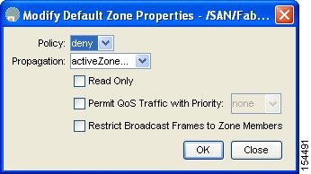
Step 4 ![]() Set the Policy drop-down menu to permit to permit traffic in the default zone, or set it to deny to block traffic in the default zone.
Set the Policy drop-down menu to permit to permit traffic in the default zone, or set it to deny to block traffic in the default zone.
Step 5 ![]() Click OK to save these changes.
Click OK to save these changes.
About Broadcast Zoning
Note ![]() Broadcast zoning is not supported on the Cisco Fabric Switch for HP c-Class BladeSystem and the Cisco Fabric Switch for IBM BladeCenter.
Broadcast zoning is not supported on the Cisco Fabric Switch for HP c-Class BladeSystem and the Cisco Fabric Switch for IBM BladeCenter.
You can configure broadcast frames in the basic zoning mode. By default, broadcast zoning is disabled and broadcast frames are sent to all Nx ports in the VSAN. When enabled, broadcast frames are only sent to Nx ports in the same zone, or zones, as the sender. Enable broadcast zoning when a host or storage device uses this feature.
Table 5-2 identifies the rules for the delivery of broadcast frames.
Tip ![]() If any NL port attached to an FL port shares a broadcast zone with the source of the broadcast frame, then the frames are broadcast to all devices in the loop.
If any NL port attached to an FL port shares a broadcast zone with the source of the broadcast frame, then the frames are broadcast to all devices in the loop.
Configuring Broadcast Zoning
To broadcast frames in the basic zoning mode using Fabric Manager, follow these steps:
Step 1 ![]() Expand a VSAN and then select a zone set in the Logical Domains pane.
Expand a VSAN and then select a zone set in the Logical Domains pane.
Step 2 ![]() Click the Policies tab in the Information pane.
Click the Policies tab in the Information pane.
You see the Zone policy information in the Information pane in Figure 5-40.
Figure 5-40 Zone Policy Information
Step 3 ![]() Check the Broadcast check box to enable broadcast frames on the default zone.
Check the Broadcast check box to enable broadcast frames on the default zone.
Step 4 ![]() Click Apply Changes to save these changes.
Click Apply Changes to save these changes.
About LUN Zoning
Logical unit number (LUN) zoning is a feature specific to switches in the Cisco MDS 9000 Family.
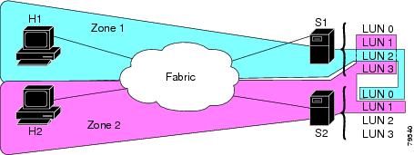
A storage device can have multiple LUNs behind it. If the device port is part of a zone, a member of the zone can access any LUN in the device. With LUN zoning, you can restrict access to specific LUNs associated with a device.
Note ![]() When LUN 0 is not included within a zone, then, as per standards requirements, control traffic to LUN 0 (for example, REPORT_LUNS, INQUIRY) is supported, but data traffic to LUN 0 (for example, READ, WRITE) is denied.
When LUN 0 is not included within a zone, then, as per standards requirements, control traffic to LUN 0 (for example, REPORT_LUNS, INQUIRY) is supported, but data traffic to LUN 0 (for example, READ, WRITE) is denied.
•![]() Host H1 can access LUN 2 in S1 and LUN 0 in S2. It cannot access any other LUNs in S1 or S2.
Host H1 can access LUN 2 in S1 and LUN 0 in S2. It cannot access any other LUNs in S1 or S2.
•![]() Host H2 can access LUNs 1 and 3 in S1 and only LUN 1 in S2. It cannot access any other LUNs in S1 or S2.
Host H2 can access LUNs 1 and 3 in S1 and only LUN 1 in S2. It cannot access any other LUNs in S1 or S2.
Note ![]() Unzoned LUNs automatically become members of the default zone.
Unzoned LUNs automatically become members of the default zone.
Figure 5-41 shows a LUN-based zone example.
Figure 5-41 LUN Zoning Access
Configuring a LUN-Based Zone
To configure a LUN-based zone using Fabric Manager, follow these steps:
Step 1 ![]() Choose Zone > Edit Local Full Zone Database.
Choose Zone > Edit Local Full Zone Database.
You see the Select VSAN dialog box.
Step 2 ![]() Select a VSAN and click OK.
Select a VSAN and click OK.
You see the Edit Local Full Zone Database dialog box for the selected VSAN.
Step 3 ![]() Click the zone where you want to add members and click the Insert icon.
Click the zone where you want to add members and click the Insert icon.
You see the Add Member to Zone dialog box shown in Figure 5-42.
Figure 5-42 Add Member to Zone Dialog Box
Step 4 ![]() Click either the WWN or FCID radio button from the Zone By options to create a LUN-based zone.
Click either the WWN or FCID radio button from the Zone By options to create a LUN-based zone.
Step 5 ![]() Check the LUN check box and click the browse button to configure LUNs.
Check the LUN check box and click the browse button to configure LUNs.
Step 6 ![]() Click Add to add this LUN-based zone.
Click Add to add this LUN-based zone.
Assigning LUNs to Storage Subsystems
LUN masking and mapping restricts server access to specific LUNs. If LUN masking is enabled on a storage subsystem and if you want to perform additional LUN zoning in a Cisco MDS 9000 Family switch, obtain the LUN number for each host bus adapter (HBA) from the storage subsystem and then configure the LUN-based zone procedure provided in the "Configuring a LUN-Based Zone" section.
Note ![]() Refer to the relevant user manuals to obtain the LUN number for each HBA.
Refer to the relevant user manuals to obtain the LUN number for each HBA.
About Read-Only Zones
By default, an initiator has both read and write access to the target's media when they are members of the same Fibre Channel zone. The read-only zone feature allows members to have only read access to the media within a read-only Fibre Channel zone.
You can also configure LUN zones as read-only zones.
Any zone can be identified as a read-only zone. By default all zones have read-write permission unless explicitly configured as a read-only zone.
Follow these guidelines when configuring read-only zones:
•![]() If read-only zones are implemented, the switch prevents write access to user data within the zone.
If read-only zones are implemented, the switch prevents write access to user data within the zone.
•![]() If two members belong to a read-only zone and to a read-write zone, the read-only zone takes priority and write access is denied.
If two members belong to a read-only zone and to a read-write zone, the read-only zone takes priority and write access is denied.
•![]() LUN zoning can only be implemented in Cisco MDS 9000 Family switches. If LUN zoning is implemented in a switch, you cannot configure interop mode in that switch.
LUN zoning can only be implemented in Cisco MDS 9000 Family switches. If LUN zoning is implemented in a switch, you cannot configure interop mode in that switch.
•![]() Read-only volumes are not supported by some operating system and file system combinations (for example, Windows NT or Windows 2000 and NTFS file system). Volumes within read-only zones are not available to such hosts. However, if these hosts are already booted when the read-only zones are activated, then read-only volumes are available to those hosts.
Read-only volumes are not supported by some operating system and file system combinations (for example, Windows NT or Windows 2000 and NTFS file system). Volumes within read-only zones are not available to such hosts. However, if these hosts are already booted when the read-only zones are activated, then read-only volumes are available to those hosts.
The read-only zone feature behaves as designed if either the FAT16 or FAT32 file system is used with the previously mentioned Windows operating systems.
Configuring Read-Only Zones
To configure read-only zones using Fabric Manager, follow these steps:
Step 1 ![]() Choose Zone > Edit Local Full Zone Database.
Choose Zone > Edit Local Full Zone Database.
You see the Select VSAN dialog box.
Step 2 ![]() Select a VSAN and click OK.
Select a VSAN and click OK.
You see the Edit Local Full Zone Database dialog box for the selected VSAN.
Step 3 ![]() Click Zones in the left pane and click the Insert icon to add a zone.
Click Zones in the left pane and click the Insert icon to add a zone.
You see the Create Zone Dialog Box as shown in Figure 5-43.
Figure 5-43 Create Zone Dialog Box

Step 4 ![]() Check the Read Only check box to create a read-only zone.
Check the Read Only check box to create a read-only zone.
Step 5 ![]() Click OK.
Click OK.
Note ![]() To configure the read-only option for a default zone, see "Configuring the Default Zone Policy" section.
To configure the read-only option for a default zone, see "Configuring the Default Zone Policy" section.
Displaying Zone Information
To view zone information and statistics using Fabric Manager, follow these steps:
Step 1 ![]() Expand a VSAN and select a zone set in the Logical Domains pane.
Expand a VSAN and select a zone set in the Logical Domains pane.
You see the zone configuration in the Information pane.
Step 2 ![]() Click the Read Only Violations, Statistics tab, or LUN Zoning Statistics tab to view statistics for the selected zone.
Click the Read Only Violations, Statistics tab, or LUN Zoning Statistics tab to view statistics for the selected zone.
Enhanced Zoning
The zoning feature complies with the FC-GS-4 and FC-SW-3 standards. Both standards support the basic zoning functionalities explained in the previous section and the enhanced zoning functionalities described in this section.
This section includes the following topics:
•![]() Changing from Basic Zoning to Enhanced Zoning
Changing from Basic Zoning to Enhanced Zoning
•![]() Changing from Enhanced Zoning to Basic Zoning
Changing from Enhanced Zoning to Basic Zoning
•![]() Configuring Zone Merge Control Policies
Configuring Zone Merge Control Policies
About Enhanced Zoning
Table 5-3 lists the advantages of the enhanced zoning feature in all switches in the Cisco MDS 9000 Family.
Changing from Basic Zoning to Enhanced Zoning
To change to the enhanced zoning mode from the basic mode, follow these steps:
Step 1 ![]() Verify that all switches in the fabric are capable of working in the enhanced mode.
Verify that all switches in the fabric are capable of working in the enhanced mode.
If one or more switches are not capable of working in enhanced mode, then your request to move to enhanced mode is rejected.
Step 2 ![]() Set the operation mode to enhanced zoning mode. By doing so, you will automatically start a session, acquire a fabric wide lock, distribute the active and full zoning database using the enhanced zoning data structures, distribute zoning policies and then release the lock. All switches in the fabric then move to the enhanced zoning mode.
Set the operation mode to enhanced zoning mode. By doing so, you will automatically start a session, acquire a fabric wide lock, distribute the active and full zoning database using the enhanced zoning data structures, distribute zoning policies and then release the lock. All switches in the fabric then move to the enhanced zoning mode.
Tip ![]() After moving from basic zoning to enhanced zoning, we recommend that you save the running configuration.
After moving from basic zoning to enhanced zoning, we recommend that you save the running configuration.
Changing from Enhanced Zoning to Basic Zoning
The standards do not allow you to move back to basic zoning. However, Cisco MDS switches allow this move to enable you to downgrade and upgrade to other Cisco SAN-OS or Cisco NX-OS releases.
To change to the basic zoning mode from the enhanced mode, follow these steps:
Step 1 ![]() Verify that the active and full zone set do not contain any configuration that is specific to the enhanced zoning mode.
Verify that the active and full zone set do not contain any configuration that is specific to the enhanced zoning mode.
If such configurations exist, delete them before proceeding with this procedure. If you do not delete the existing configuration, the Cisco NX-OS software automatically removes them.
Step 2 ![]() Set the operation mode to basic zoning mode. By doing so, you will automatically start a session, acquire a fabric wide lock, distribute the zoning information using the basic zoning data structure, apply the configuration changes and release the lock from all switches in the fabric. All switches in the fabric then move to basic zoning mode.
Set the operation mode to basic zoning mode. By doing so, you will automatically start a session, acquire a fabric wide lock, distribute the zoning information using the basic zoning data structure, apply the configuration changes and release the lock from all switches in the fabric. All switches in the fabric then move to basic zoning mode.
Note ![]() If a switch running Cisco SAN-OS Release 2.0(1b) and NX-OS 4(1b) or later, with enhanced zoning enabled is downgraded to Cisco SAN-OS Release 1.3(4), or earlier, the switch comes up in basic zoning mode and cannot join the fabric because all the other switches in the fabric are still in enhanced zoning mode.
If a switch running Cisco SAN-OS Release 2.0(1b) and NX-OS 4(1b) or later, with enhanced zoning enabled is downgraded to Cisco SAN-OS Release 1.3(4), or earlier, the switch comes up in basic zoning mode and cannot join the fabric because all the other switches in the fabric are still in enhanced zoning mode.
Enabling Enhanced Zoning
By default, the enhanced zoning feature is disabled in all switches in the Cisco MDS 9000 Family.
To enable enhanced zoning in a VSAN using Fabric Manager, follow these steps:
Step 1 ![]() Expand a VSAN and then select a zone set in the Logical Domains pane.
Expand a VSAN and then select a zone set in the Logical Domains pane.
You see the zone set configuration in the Information pane.
Step 2 ![]() Click the Enhanced tab.
Click the Enhanced tab.
You see the current enhanced zoning configuration.
Step 3 ![]() From the Action drop-down menu, choose enhanced to enable enhanced zoning in this VSAN.
From the Action drop-down menu, choose enhanced to enable enhanced zoning in this VSAN.
Step 4 ![]() Click Apply Changes to save these changes.
Click Apply Changes to save these changes.
Creating Attribute Groups
In enhanced mode, you can directly configure attributes using attribute groups.
To configure attribute groups, refer to the Cisco MDS 9000 Family CLI Configuration Guide.
Merging the Database
The merge behavior depends on the fabric-wide merge control setting:
•![]() Restrict—If the two databases are not identical, the ISLs between the switches are isolated.
Restrict—If the two databases are not identical, the ISLs between the switches are isolated.
•![]() Allow—The two databases are merged using the merge rules specified in Table 5-4.
Allow—The two databases are merged using the merge rules specified in Table 5-4.
|
|
|
|
|
|---|---|---|---|
The databases contain zone sets with the same name1 but different zones, aliases, and attributes groups. |
Successful. |
The union of the local and adjacent databases. |
|
The databases contains a zone, zone alias, or zone attribute group object with same name1 but different members. |
Failed. |
ISLs are isolated. |
|
Empty. |
Contains data. |
Successful. |
The adjacent database information populates the local database. |
Contains data. |
Empty. |
Successful. |
The local database information populates the adjacent database. |
1 In the enhanced zoning mode, the active zone set does not have a name in interop mode 1. The zone set names are only present for full zone sets. |
The merge process operates as follows:
1. ![]() The software compares the protocol versions. If the protocol versions differ, then the ISL is isolated.
The software compares the protocol versions. If the protocol versions differ, then the ISL is isolated.
2. ![]() If the protocol versions are the same, then the zone policies are compared. If the zone policies differ, then the ISL is isolated.
If the protocol versions are the same, then the zone policies are compared. If the zone policies differ, then the ISL is isolated.
3. ![]() If the zone merge options are the same, then the comparison is implemented based on the merge control setting.
If the zone merge options are the same, then the comparison is implemented based on the merge control setting.
a. ![]() If the setting is restrict, the active zone set and the full zone set should be identical. Otherwise the link is isolated.
If the setting is restrict, the active zone set and the full zone set should be identical. Otherwise the link is isolated.
b. ![]() If the setting is allow, then the merge rules are used to perform the merge.
If the setting is allow, then the merge rules are used to perform the merge.
Analyzing a Zone Merge
To perform a zone merge analysis using Fabric Manager, follow these steps:
Step 1 ![]() Choose Zone > Merge Analysis.
Choose Zone > Merge Analysis.
You see the Zone Merge Analysis dialog box shown in Figure 5-44.
Figure 5-44 Zone Merge Analysis Dialog Box
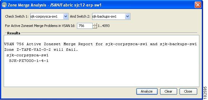
Step 2 ![]() Select the first switch to be analyzed from the Check Switch 1 drop-down list.
Select the first switch to be analyzed from the Check Switch 1 drop-down list.
Step 3 ![]() Select the second switch to be analyzed from the And Switch 2 drop-down list.
Select the second switch to be analyzed from the And Switch 2 drop-down list.
Step 4 ![]() Enter the VSAN ID where the zone set merge failure occurred in the For Active Zoneset Merge Problems in VSAN Id field.
Enter the VSAN ID where the zone set merge failure occurred in the For Active Zoneset Merge Problems in VSAN Id field.
Step 5 ![]() Click Analyze to analyze the zone merge.
Click Analyze to analyze the zone merge.
Step 6 ![]() Click Clear to clear the analysis data in the Zone Merge Analysis dialog box.
Click Clear to clear the analysis data in the Zone Merge Analysis dialog box.
Configuring Zone Merge Control Policies
To configure merge control policies, refer to the Cisco MDS 9000 Family CLI Configuration Guide.
Zone generic service permission setting is used to control zoning operation through generic service (GS) interface. The zone generic service permission can be read-only, read-write or none (deny).
To configure generic service (GS) settings, follow these steps:
Compacting the Zone Database for Downgrading
Prior to Cisco SAN-OS Release 3.0(1), only 2000 zones are supported per VSAN. If you add more than 2000 zones to a VSAN, a configuration check is registered to indicate that downgrading to a previous release could cause you to lose the zones over the limit. To avoid the configuration check, delete the excess zones and compact the zone database for the VSAN. If there are 2000 zones or fewer after deleting the excess zones, the compacting process assigns new internal zone IDs and the configuration can be supported by Cisco SAN-OS Release 2.x or earlier. Perform this procedure for every VSAN on the switch with more than 2000 zones.
Note ![]() A merge failure occurs when a switch supports more than 2000 zones per VSAN but its neighbor does not. Also, zone set activation can fail if the switch has more than 2000 zones per VSAN and not all switches in the fabric support more than 2000 zones per VSAN.
A merge failure occurs when a switch supports more than 2000 zones per VSAN but its neighbor does not. Also, zone set activation can fail if the switch has more than 2000 zones per VSAN and not all switches in the fabric support more than 2000 zones per VSAN.
To compact the zone database for downgrading, refer to the Cisco MDS 9000 Family CLI Configuration Guide.
Default Settings
Table 5-5 lists the default settings for basic zone parameters.
 Feedback