High Availability Overview

You can configure the high availability (HA) software framework and redundancy features using CLI. These features include application restartability and nondisruptive supervisor switchability. Cisco high availability is a technology that is delivered in Cisco NX-OS software that enables networkwide resilience to increase network availability.

The Cisco MDS Multilayer Directors and switches support application restartability and nondisruptive supervisor switchability. The switches are protected from system failure by redundant hardware components and a high availability software framework.

The high availability software framework enables the following features:

  • Ensures nondisruptive software upgrade capability.

  • Provides redundancy for supervisor module failure by using dual supervisor modules.

  • Performs nondisruptive restarts of failed process on the same supervisor module. A service running on the supervisor and the switching modules tracks the high availability policy that is defined in the configuration and takes action based on the policy. This feature is also available in the Cisco MDS 9200 and MDS 9100 switches.

  • Protects against a link failure using the port channel (port aggregation) feature. This feature is also available in the Cisco MDS 9200 and MDS 9100 switches.

  • Provides switchovers when an active supervisor fails. The standby supervisor, if present, takes over without disrupting storage or host traffic.

  • Enables the Cisco MDS switches to detect CRC errors that occur internally within a switch and isolate the source of the errors.

Supervisor Redundancy

Cisco MDS Director switches have two supervisor modules for redundancy. When the switch powers up and both supervisor modules are present, the supervisor module that comes up first enters the active mode and the supervisor module that comes up second enters the standby mode. The supervisor in active mode is in control of the switch. It performs all the necessary functions to ensure that all the switch's components are operating normally. The standby supervisor module constantly monitors the active supervisor module. If the active supervisor module fails, the standby supervisor module takes over without any impact to the user traffic. If the failed supervisor recovers, it will become the standby supervisor and monitors the new active supervisor.

Prior to Cisco MDS NX-OS Release 8.4(2), the standby supervisor's management Ethernet link on Cisco MDS Director switches was down. Therefore, the peer port of the management link was also down and could be mistaken as an unused port. This unused port could either be mistakenly disabled or repurposed. If a switchover occurred, the management link on the newly active supervisor would not be available and the switch would become unmanageable because there would be no active connection to the newly active supervisor's management port.

From Cisco MDS NX-OS Release 8.4(2), the standby supervisor's management Ethernet link on Cisco MDS Director switches is brought up when the supervisor reaches the standby state. However, no upper layer protocols, such as IP, are active. This allows the peer port of the standby supervisor's management link to be up and not mistakenly disabled or repurposed due to being down for a long duration.


Note


For out of band management with high availability in director switches, you must connect the mgmt0 port of both supervisors to the same subnet or virtual LAN since the mgmt0 IP address will be used by whichever supervisor is currently active.


Internal CRC Detection and Isolation

Beginning with the Cisco MDS NX-OS Release 6.2(13), the Internal Cyclic Redundancy Check (CRC) detection and isolation functionality is supported on the Cisco MDS 9700 series switches.

This functionality enables the Cisco MDS switches to detect CRC errors that occur internally within a switch and isolate the source of these errors.


Note


Internal CRC Detection and Isolation is supported only on the Cisco MDS 9700 Series Multilayer Directors.


From NX-OS Release 8.5(1) and Release 9.2(1), the internal CRC detection and isolation feature is enabled, by default, to log instances of 3 internal CRC errors per 24-hour period without taking any action.

The modules that support this functionality are:

  • Cisco MDS 9700 48-Port 64-Gbps Fibre Channel Switching Module

  • Cisco MDS 9700 48-Port 16-Gbps Fibre Channel Switching Module

  • Cisco MDS 9700 48-Port 10-Gbps Fibre Channel over Ethernet Switching Module

  • Cisco MDS 9700 40-Gbps 24-Port Fibre Channel over Ethernet Switching Module

  • Cisco MDS 24/10-Port SAN Extension Switching Module

  • Cisco MDS 9700 48-Port 32-Gbps Fibre Channel Switching Module

  • Cisco MDS 9700 Fabric Module 1

  • Cisco MDS 9700 Fabric Module 3

  • Cisco MDS 9700 Supervisor Module 1

  • Cisco MDS 9700 Supervisor Module 4


Note


Module refers either a switching module or a supervisor module.


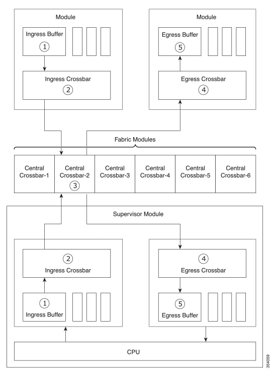
These internal CRC errors are a separate class of CRC errors when compared to frames that arrive from outside the switch, with CRC errors. Frames that arrive from outside the switch on links are checked at ingress. If a frame does not pass the ingress CRC check it is dropped at the ingress port and does not propagate through the system. MDS switches including MDS 9700 directors operate in store and forward mode. Internal CRC errors occur when frames are received without errors, but get corrupted when they pass through the switching path. This corruption can occur in 5 'stages' in the forwarding path.

Internal CRC errors are usually caused by a fault in the system. Such faults may be transient, such as an ungracefully removed module, or permanent, such as a badly seated module, or, in rare cases, a failing or failed hardware component. The rate of errors depends on many factors and may range from very high to very low.

The error-rate threshold is configurable as a system-wide value, but separate error counts are maintained for each ASIC on each module to identify an error source.

When an ASIC involved in frame forwarding receives a frame it is CRC checked. If the CRC check does not pass then normally it is the receiving ASIC that is the faulty ASIC. However, it is possible that it was corrupted and sent incorrectly by the transmitting ASIC or corrupted along the link between the two ASICs. Depending on which ASIC or other component is at fault the errors may isolated to the single ASIC or they may be occurring on multiple ASICs if, for example, a faulty ASIC is transmitting to multiple receiving ASICs. Determining the faulty component involves understanding the multiple stages and looking at all of the internal CRC errors that are occurring.


Note


The counters are reset at 24 hours from the time the feature, the Internal Cyclic Redundancy Check (CRC) detection and isolation was first configured.

Stages of Internal CRC Detection and Isolation

The five possible stages at which internal CRC errors may occur in a switch:

  1. Stage 1—Ingress Buffer of a Module

  2. Stage 2—Ingress Crossbar of a Module

  3. Stage 3—Central Crossbar of a Chassis

  4. Stage 4—Egress crossbar of a Module

  5. Stage 5—Egress Buffer of a Module

Figure 1. Stages of Internal CRC Detection and Isolation


Errors on each module are handled individually when the error count exceeds the threshold.


Note


A total of errors on all applicable ASICs on the module must exceed the threshold.


When errors cross the specified threshold, XBAR_MONITOR_INTERNAL_CRC_ERR is the syslog message that is logged. This syslog message specifies the location of the error and the type of action taken.

Example: Error Messages

switch# show logging logfile | inc MONITOR_INTERNAL_CRC_ERR
2015 May 25 21:20:41 switch %XBAR-2-XBAR_MONITOR_INTERNAL_CRC_ERR: Module-1 detects CRC
Error:4 at Egress Q-engine, putting it in failure state
2015 May 25 21:15:35 switch %XBAR-2-XBAR_MONITOR_INTERNAL_CRC_ERR: Fab_slot-12 detects CRC
error:1 at ingress stage2, putting it in failure state
2015 May 25 15:47:10 switch %XBAR-2-XBAR_MONITOR_INTERNAL_CRC_ERR: Module-5 detects CRC
error:2 at Ingress Qengine, Only one Sup is present, bringing down the active VSAN
2015 May 25 15:08:17 switch %XBAR-2-XBAR_MONITOR_INTERNAL_CRC_ERR: Module-5 detects CRC
error:1 at Ingress Qengine, putting it in failure state

Stage 1—Ingress Buffer of a Module

There are multiple ingress buffers on each module. When the CRC error rate of an ingress buffer on a switching module reaches the threshold, the entire module is shut down. See Actions Taken on a Supervisor when the Threshold Exceeded for more information.

Stage 2—Ingress Crossbar of a Module

Ingress crossbar is an ASIC complex on an ingress module that switches traffic from ingress buffers to fabric modules. When the CRC error rate of an ingress switching module crossbar reaches the threshold, the entire module is shut down. See Actions Taken on a Supervisor when the Threshold Exceeded for more information.

Stage 3—Central Crossbar of a Chassis

Crossbar is an ASIC complex on a fabric module that switches traffic from an ingress module to an egress module.

When the CRC error rate of a crossbar reaches the threshold, if there is more than one fabric module in the corresponding switch, the fabric module recording the errors is shut down. If the switch has only one fabric module, the module connected to the fabric module link on which the errors occurred is shut down.

Stage 4—Egress Crossbar of a Module

Egress crossbar is an ASIC complex on an egress module that switches traffic from fabric modules to egress buffers. When the CRC error rate of an egress switching module crossbar reaches the threshold, the connected central crossbar where the frame that has an error was received is powered down. See Actions Taken on a Supervisor when the Threshold Exceeded for more information.

Stage 5—Egress Buffer of a Module

There are multiple egress buffers on each module. When the CRC error rate of an egress buffer on a switching module reaches the threshold, the entire module is shut down. See Actions Taken on a Supervisor when the Threshold Exceeded for more information.

Actions Taken on a Supervisor when the Threshold Exceeded

The actions taken on a supervisor when the threshold is exceeded during the following stages of internal CRC detection and isolation:

  1. Stage 1—Ingress Buffer of a Module

  2. Stage 2—Ingress Crossbar of a Module

  3. Stage 4—Egress Crossbar of a Module

  4. Stage 5—Egress Buffer of a Module


Note


  • When both active and standby supervisors are present in the switch, the active supervisor is brought down and the standby takes over.

  • When only active supervisor is present in the switch (second supervisor is absent or down), all active VSANs are suspended so that the data traffic stops. The active supervisor is available for manual debugging.

  • When both a single fabric module is present and and a single supervisor module is present and Stage 2 errors occur on the supervisor, the supervisor is powered down; as a result the switch is brought down.


For information on configuring the Internal CRC Detection and Isolation feature, see Configuring Internal CRC Detection and Isolation.