Configuring N Port Virtualization
Information About N Port Virtualization
This section includes the following topics:
- NPV Overview
- N Port Identifier Virtualization
- N Port Virtualization
- NPV Mode
- NP Ports
- NP Links
- Default Port Numbers
- NPV CFS Distribution over IP
- NPV Traffic Management
- Multiple VSAN Support
NPV Overview
N port virtualization (NPV) reduces the number of Fibre Channel domain IDs in SANs. Switches operating in the NPV mode do not join a fabric. They pass traffic between NPV core switch links and end devices, which eliminates the domain IDs for these edge switches.
NPV is supported by the following Cisco MDS 9000 switches and Cisco Nexus 5000 Series switches only:
- Cisco MDS 9124 Multilayer Fabric Switch
- Cisco MDS 9134 Fabric Switch
- Cisco MDS 9148 Multilayer Fabric Switch
- Cisco Fabric Switch for HP c-Class BladeSystem
- Cisco Fabric Switch for IBM BladeCenter
- Cisco Nexus 5000 Series switches

Note![]() NPV is available on these switches only while in NPV mode; if in switch mode, NPV is not available.
NPV is available on these switches only while in NPV mode; if in switch mode, NPV is not available.
N Port Identifier Virtualization
N port identifier virtualization (NPIV) provides a means to assign multiple FC IDs to a single N port. This feature allows multiple applications on the N port to use different identifiers and allows access control, zoning, and port security to be implemented at the application level. Figure 7-1 shows an example application using NPIV.
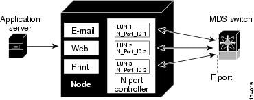
You must globally enable NPIV for all VSANs on the MDS switch to allow the NPIV-enabled applications to use multiple N port identifiers.
Note![]() All of the N port identifiers are allocated in the same VSAN.
All of the N port identifiers are allocated in the same VSAN.
N Port Virtualization
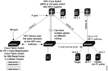
Typically, Fibre Channel networks are deployed using a core-edge model with a large number of fabric switches connected to edge devices. Such a model is cost-effective because the per port cost for director class switches is much higher than that of fabric switches. However, as the number of ports in the fabric increases, the number of switches deployed also increases, and you can end up with a significant increase in the number of domain IDs (the maximum number supported is 239). This challenge becomes even more difficult when additional blade chassis are deployed in Fibre Channel networks.
NPV addresses the increase in the number of domain IDs needed to deploy a large number of the ports by making a fabric or blade switch appear as a host to the core Fibre Channel switch, and as a Fibre Channel switch to the servers in the fabric or blade switch. NPV aggregates multiple locally connected N ports into one or more external NP links, which shares the domain ID of the NPV core switch among multiple NPV switches. NPV also allows multiple devices to attach to same port on the NPV core switch, which reduces the need for more ports on the core.
Figure 7-2 Cisco NPV Fabric Configuration
While NPV is similar to N port identifier virtualization (NPIV), it does not offer exactly the same functionality. NPIV provides a means to assign multiple FC IDs to a single N port, and allows multiple applications on the N port to use different identifiers. NPIV also allows access control, zoning, and port security to be implemented at the application level. NPV makes use of NPIV to get multiple FCIDs allocated from the core switch on the NP port.
Figure 7-3 shows a more granular view of an NPV configuration at the interface level.
Figure 7-3 Cisco NPV Configuration–Interface View
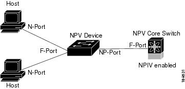
NPV Mode
A switch is in NPV mode after a user has enabled NPV and the switch has successfully rebooted. NPV mode applies to an entire switch. All end devices connected to a switch that is in NPV mode must log in as an N port to use this feature (loop-attached devices are not supported). All links from the edge switches (in NPV mode) to the NPV core switches are established as NP ports (not E ports), which are used for typical interswitch links. NPIV is used by the switches in NPV mode to log in to multiple end devices that share a link to the NPV core switch.
Note![]() In-order data delivery is not required in NPV mode because the exchange between two end devices always takes the same uplink to the core from the NPV device. For traffic beyond the NPV device, core switches will enforce in-order delivery if needed and/or configured.
In-order data delivery is not required in NPV mode because the exchange between two end devices always takes the same uplink to the core from the NPV device. For traffic beyond the NPV device, core switches will enforce in-order delivery if needed and/or configured.
After entering NPV mode, only the following commands are available:
NP Ports
An NP port (proxy N port) is a port on a device that is in NPV mode and connected to the NPV core switch using an F port. NP ports behave like N ports except that in addition to providing N port behavior, they also function as proxies for multiple, physical N ports.
NP Links
An NP link is basically an NPIV uplink to a specific end device. NP links are established when the uplink to the NPV core switch comes up; the links are terminated when the uplink goes down. Once the uplink is established, the NPV switch performs an internal FLOGI to the NPV core switch, and then (if the FLOGI is successful) registers itself with the NPV core switch’s name server. Subsequent FLOGIs from end devices in this NP link are converted to FDISCs. For more details refer to the “Internal FLOGI Parameters” section.
Server links are uniformly distributed across the NP links. All the end devices behind a server link will be mapped to only one NP link.
Internal FLOGI Parameters
When an NP port comes up, the NPV device first logs itself in to the NPV core switch and sends a FLOGI request that includes the following parameters:
- The fWWN (fabric port WWN) of the NP port used as the pWWN in the internal login.
- The VSAN-based sWWN (switch WWN) of the NPV device used as nWWN (node WWN) in the internal FLOGI.
After completing its FLOGI request, the NPV device registers itself with the fabric name server using the following additional parameters:
- Switch name and interface name (for example, fc1/4) of the NP port is embedded in the symbolic port name in the name server registration of the NPV device itself.
- The IP address of the NPV device is registered as the IP address in the name server registration of the NPV device.
Note![]() The BB_SCN of internal FLOGIs on NP ports is always set to zero. The BB_SCN is supported at the F-port of the NPV device.
The BB_SCN of internal FLOGIs on NP ports is always set to zero. The BB_SCN is supported at the F-port of the NPV device.
Figure 7-4 shows the internal FLOGI flows between an NPV core switch and an NPV device.
Figure 7-4 Internal FLOGI Flows
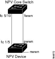
Table 7-1 identifies the internal FLOGI parameters that appear in Figure 7-4.
|
|
|
|---|---|
The switch name and NP port interface string. Note If there is no switch name available, then the output will display “switch.” For example, switch: fc1/5. |
|
Although fWWN-based zoning is supported for NPV devices, it is not recommended because:
- Zoning is not enforced at the NPV device (rather, it is enforced on the NPV core switch).
- Multiple devices behind an NPV device log in via the same F port on the core (they use same fWWN and cannot be separated into different zones).
- The same device might log in using different fWWNs on the core switch (depending on the NPV link it uses) and may need to be zoned using different fWWNs.
Default Port Numbers
Port numbers on NPV-enabled switches will vary depending on the switch model. For details about port numbers for NPV-eligible switches, see the Cisco NX-OS Family Licensing Guide.
NPV CFS Distribution over IP
NPV devices use only IP as the transport medium. CFS uses multicast forwarding for CFS distribution. NPV devices do not have ISL connectivity and FC domain. To use CFS over IP, multicast forwarding has to be enabled on the Ethernet IP switches all along the network that physically connects the NPV switch. You can also manually configure the static IP peers for CFS distribution over IP on NPV-enabled switches. For more information, see the Cisco MDS 9000 Family NX-OS System Management Configuration Guide.
NPV Traffic Management
This sections discusses the following aspects of load balancing:
Auto
Before Cisco MDS SAN-OS Release 3.3(1a), NPV supported automatic selection of external links. When a server interface is brought up, an external interface with the minimum load is selected from the available links. There is no manual selection on the server interfaces using the external links. Also, when a new external interface was brought up, the existing load was not distributed automatically to the newly available external interface. This newly brought up interface is used only by the server interfaces that come up after this interface.
Traffic Map
As in Cisco MDS SAN-OS Release 3.3(1a) and NX-OS Release 4.1(1a), NPV supports traffic management by allowing you to select and configure the external interfaces that the server uses to connect to the core switches.
Note![]() When the NPV traffic management is configured, the server uses only the configured external interfaces. Any other available external interface will not be used.
When the NPV traffic management is configured, the server uses only the configured external interfaces. Any other available external interface will not be used.
The NPV traffic management feature provides the following benefits:
- Facilitates traffic engineering by providing dedicated external interfaces for the servers connected to NPV.
- Uses the shortest path by selecting external interfaces per server interface.
- Uses the persistent FC ID feature by providing the same traffic path after a link break, or reboot of the NPV or core switch.
- Balances the load by allowing the user to evenly distribute the load across external interfaces.
Disruptive
Disruptive load balance works independent of automatic selection of interfaces and a configured traffic map of external interfaces. This feature forces reinitialization of the server interfaces to achieve load balance when this feature is enabled and whenever a new external interface comes up. To avoid flapping the server interfaces too often, enable this feature once and then disable it whenever the needed load balance is achieved.
If disruptive load balance is not enabled, you need to manually flap the server interface to move some of the load to a new external interface.
Multiple VSAN Support
By grouping devices into different NPV sessions based on VSANs, it is possible to support multiple VSANs on the NPV-enabled switch. The correct uplink must be selected based on the VSAN that the uplink is carrying.
Guidelines and Limitations
This section includes the guidelines and limitations for this feature:
- NPV Guidelines and Requirements
- NPV Traffic Management Guidelines
- DPVM Configuration Guidelines
- NPV and Port Security Configuration Guidelines
NPV Guidelines and Requirements
Following are recommended guidelines and requirements when deploying NPV:
- NPV core switches must support NPIV.
- You can have up to 100 NPV devices.
- Nondisruptive upgrades are supported. See the Cisco MDS 9000 Family NX-OS Fundamentals Configuration Guide.
- Port tracking is supported. See the Cisco MDS 9000 Family NX-OS Security Configuration Guide.
- You can configure zoning for end devices that are connected to NPV devices using all available member types on the NPV core switch. If fWWN, sWWN, domain, or port-based zoning is used, then fWWN, sWWN or the domain/port of the NPV core switch should be used.
- Port security is supported on the NPV core switch for devices logged in via NPV.
- NPV uses a load-balancing algorithm to automatically assign end devices in a VSAN to one of the NPV core switch links (in the same VSAN) upon initial login. If there are multiple NPV core switch links in the same VSAN, then you cannot assign a specific one to an end device.
- Both servers and targets can be connected to an NPV device.
- Remote SPAN is not supported.
- Local switching is not supported; all traffic is switched using the NPV core switch.
- NPV devices can connect to multiple NPV core switches. In other words, different NP ports can be connected to different NPV core switches.
- NPV supports NPIV-capable module servers (nested NPIV).
- Only F, NP, and SD ports are supported in NPV mode.
- In the case of servers that are booted over the SAN with NPV, if an NPV link failover occurs, servers will lose access to their boot LUN temporarily.
- NPV switches do not recognize the BB_SCN configuration on the xNP ports because of interoperability issues with the third-party core switches.
NPV Traffic Management Guidelines
When deploying NPV traffic management, follow these guidelines:
- Use NPV traffic management only when the automatic traffic engineering by the NPV device is not sufficient for the network requirements.
- Do not configure traffic maps for all the servers. For non-configured servers, NPV will use automatic traffic engineering.
- Configure the Persistent FC ID on the core switch. Traffic engineering directs the associated server interface to external interfaces that lead to the same core switch. The server will be assigned the same FC ID for every log in. This guideline is not applicable if a 91x4 switch is used as the core switch.
- Server interfaces configured to a set of external interfaces cannot use any other available external interfaces, even if the configured interfaces are not available.
- Do not configure disruptive load balancing because this involves moving a device from one external interface to another interface. Moving the device between external interfaces requires NPV relogin to the core switch through F port leading to traffic disruption.
- Link a set of servers to a core switch by configuring the server to a set of external interfaces that are linked to the core switch.
DPVM Configuration Guidelines
When NPV is enabled, the following requirements must be met before you configure DPVM on the NPV core switch:
- You must explicitly configure the WWN of the internal FLOGI in DPVM. If DPVM is configured on the NPV core switch for an end device that is connected to the NPV device, then that end device must be configured to be in the same VSAN. Logins from a device connected to an NPV device will fail if the device is configured to be in a different VSAN. To avoid VSAN mismatches, ensure that the internal FLOGI VSAN matches the port VSAN of the NP port.
- The first login from an NP port determines the VSAN of that port. If DPVM is configured for this first login, which is the internal login of the NPV device, then the NPV core switch’s VSAN F port is located in that VSAN. Otherwise, the port VSAN remains unchanged.
For details about DPVM configuration, see the Cisco MDS 9000 Family NX-OS Fabric Configuration Guide.
NPV and Port Security Configuration Guidelines
Port security is enabled on the NPV core switch on a per interface basis. To enable port security on the NPV core switch for devices logging in via NPV, you must adhere to the following requirements:
- The internal FLOGI must be in the port security database so that, the port on the NPV core switch will allow communications and links.
- All of the end device pWWNs must also be in the port security database.
Once these requirements are met, you can enable port security as you would in any other context. For details about enabling port security, see the Cisco MDS 9000 Family NX-OS Security Configuration Guide.
Configuring N Port Virtualization
This section includes the following topics:
Enabling N Port Identifier Virtualization
You must globally enable NPIV for all VSANs on the MDS switch to allow the NPIV-enabled applications to use multiple N port identifiers.
Note![]() All of the N port identifiers are allocated in the same VSAN.
All of the N port identifiers are allocated in the same VSAN.
Detailed Steps
To enable or disable NPIV on the switch, follow these steps:
|
|
|
|
|---|---|---|
Configuring NPV
When you enable NPV, the system configuration is erased and the system reboots with the NPV mode enabled.
Note![]() We recommend that you save the current configuration either on bootflash or a TFTP server before NPV (if the configuration is required for later use). Use the following commands to save either your non-NPV or NPV configuration:
We recommend that you save the current configuration either on bootflash or a TFTP server before NPV (if the configuration is required for later use). Use the following commands to save either your non-NPV or NPV configuration:switch# copy running bootflash:filename
The configuration can be reapplied later using the following command:
switch#
Detailed Steps
To configure NPV using the CLI, perform the following tasks:
Configuring NPV Traffic Management
The NPV traffic management feature is enabled after configuring NPV. Configuring NPV traffic management involves configuring a list of external interfaces to the servers, and enabling or disabling disruptive load balancing.
Configuring List of External Interfaces per Server Interface
A list of external interfaces are linked to the server interfaces when the server interface is down, or if the specified external interface list includes the external interface already in use.
Detailed Steps
To configure the list of external interfaces per server interface, perform the following tasks:
|
|
|
|
|---|---|---|
switch(config)# npv traffic-map server-interface svr-if-range external-interface fc ext-fc-if-range |
Allows you to configure a list of external FC interfaces per server interface by specifying the external interfaces in the svr-if-range. The server to be linked is specified in the ext-fc-if-range. |
|
switch(config)# npv traffic-map server-interface svr-if-range external-interface port-channel ext-pc-if-range |
Allows you to configure a list of external PortChannel1 interfaces per server interface by specifying the external interfaces in the svr-if-range. The server to be linked is specified in the ext-pc-if-range. |
|
switch(config)# no npv traffic-map server-interface svr-if-range external-interface ext-if-range |
|
1.While mapping non-PortChannel interfaces and PortChannel interfaces to the server interfaces, include them separately in two steps. |
Enabling the Global Policy for Disruptive Load Balancing
Disruptive load balancing allows you to review the load on all the external interfaces and balance the load disruptively. Disruptive load balancing is done by moving the servers using heavily loaded external interfaces, to the external interfaces running with fewer loads.
Detailed Steps
To enable or disable the global policy for disruptive load balancing, perform the following tasks:
|
|
|
|
|---|---|---|
Verifying NPV Configuration
This section includes the following topics:
To display NPV configuration information, perform one of the following tasks:
For detailed information about the fields in the output from these commands, refer to the Cisco MDS NX-OS Command Reference.
Verifying NPV
To view all the NPV devices in all the VSANs that the aggregator switch belongs to, enter the show fcns database command.
For additional details (such as IP addresses, switch names, interface names) about the NPV devices you see in the show fcns database output, enter the show fcns database detail command.
If you need to contact support, enter the show tech-support NPV command and save the output so that support can use it to troubleshoot, if necessary.
To display a list of the NPV devices that are logged in, along with VSANs, source information, pWWNs, and FCIDs, enter the show npv flogi-table command.
To display the status of the different servers and external interfaces, enter the show npv status command.
Verifying NPV Traffic Management
To display the NPV traffic map, enter the show npv traffic-map command.
To display the NPV internal traffic details, enter the show npv internal info traffic-map command.
 Feedback