Interfaces Configuration Guide, Cisco DCNM for SAN, Release 6.x
Bias-Free Language
The documentation set for this product strives to use bias-free language. For the purposes of this documentation set, bias-free is defined as language that does not imply discrimination based on age, disability, gender, racial identity, ethnic identity, sexual orientation, socioeconomic status, and intersectionality. Exceptions may be present in the documentation due to language that is hardcoded in the user interfaces of the product software, language used based on RFP documentation, or language that is used by a referenced third-party product. Learn more about how Cisco is using Inclusive Language.
- Updated:
- July 18, 2011
Chapter: Configuring Port Tracking
- Information About Port Tracking
- Guidelines and Limitations
- Default Settings
- Configuring Port Tracking
- Enabling Port Tracking
- Information About Configuring Linked Ports
- Binding a Tracked Port Operationally
- Information About Tracking Multiple Ports
- Tracking Multiple Ports
- Information About Monitoring Ports in a VSAN
- Monitoring Ports in a VSAN
- Information AboutForceful Shutdown
- Forcefully Shutting Down a Tracked Port
- Displaying Port Tracking Information
Configuring Port Tracking
The port tracking feature is unique to the Cisco MDS 9000 Family of switches. This feature uses information about the operational state of the link to initiate a failure in the link that connects the edge device. This process of converting the indirect failure to a direct failure triggers a faster recovery process towards redundant links. When enabled, the port tracking feature brings down the configured links based on the failed link and forces the traffic to be redirected to another redundant link.
Information About Port Tracking
Generally, hosts can instantly recover from a link failure on a link that is immediately (direct link) connected to a switch. However, recovering from an indirect link failure between switches in a WAN or MAN fabric with a keep-alive mechanism is dependent on several factors such as the time out values (TOVs) and on registered state change notification (RSCN) information.
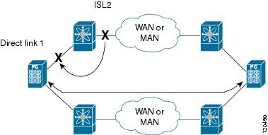
In Figure 9-1, when the direct link 1 to the host fails, recovery can be immediate. However, when the ISL 2 fails between the two switches, recovery depends on TOVs, RSCNs, and other factors.
Figure 9-1 Traffic Recovery Using Port Tracking
The port tracking feature monitors and detects failures that cause topology changes and brings down the links connecting the attached devices. When you enable this feature and explicitly configure the linked and tracked ports, the Cisco NX-OS software monitors the tracked ports and alters the operational state of the linked ports on detecting a link state change.
The following terms are used in this chapter:
- Tracked ports—A port whose operational state is continuously monitored. The operational state of the tracked port is used to alter the operational state of one or more ports. Fibre Channel, VSAN, PortChannel, FCIP, or a Gigabit Ethernet port can be tracked. Generally, ports in E and TE port modes can also be Fx ports.
- Linked ports—A port whose operational state is altered based on the operational state of the tracked ports. Only a Fibre Channel port can be linked.
Guidelines and Limitations
Before configuring port tracking, consider the following guidelines:
- Verify that the tracked ports and the linked ports are on the same Cisco MDS switch.
- Do not track a linked port back to itself (for example, Port fc1/2 to Port fc2/5 and back to Port fc1/2) to avoid recursive dependency.
- Be aware that the linked port is automatically brought down when the tracked port goes down. Be aware that the linked port is automatically brought down when the tracked port goes down.
Default Settings
Table 9-1 lists the default settings for port tracking parameters.
|
|
|
|---|---|
Configuring Port Tracking
Port tracking has the following features:
- The application brings the linked port down when the tracked port goes down. When the tracked port recovers from the failure and comes back up again, the tracked port is also brought up automatically (unless otherwise configured).
- You can forcefully continue to keep the linked port down, even though the tracked port comes back up. In this case, you must explicitly bring the port up when required.
This section includes the following topics:
- Enabling Port Tracking
- Information About Configuring Linked Ports
- Binding a Tracked Port Operationally
- Information About Tracking Multiple Ports
- Tracking Multiple Ports
- Information About Monitoring Ports in a VSAN
- Monitoring Ports in a VSAN
- Information AboutForceful Shutdown
- Forcefully Shutting Down a Tracked Port
Enabling Port Tracking
The port tracking feature is disabled by default in all switches in the Cisco 9000 Family. When you enable this feature, port tracking is globally enabled for the entire switch.
To configure port tracking, enable the port tracking feature and configure the linked port(s) for the tracked port.
Detailed Steps
To enable port tracking, follow these steps:
|
|
|
|
|---|---|---|
Removes the currently applied port tracking configuration and disables port tracking. |
Information About Configuring Linked Ports
Binding a Tracked Port Operationally
When you configure the first tracked port, operational binding is automatically in effect. When you use this method, you have the option to monitor multiple ports or monitor ports in one VSAN.
Detailed Steps
To operationally bind a tracked port, follow these steps:
|
|
|
|
|---|---|---|
Configures the specified interface and enters the interface configuration submode. You can now configure tracked ports. Note This link symbolizes the direct link (1) in Figure 9-1. |
||
Tracks interface fc8/6 with interface port-channel 1. When port-channel 1 goes down, interface fc8/6 is also brought down. Note This link symbolizes the ISL (2) in Figure 9-1. |
||
Removes the port tracking configuration that is currently applied to interface fc8/6. |
Information About Tracking Multiple Ports
You can control the operational state of the linked port based on the operational states of multiple tracked ports. When more than one tracked port is associated with a linked port, the operational state of the linked port will be set to down only if all the associated tracked ports are down. Even if one tracked port is up, the linked port will stay up.
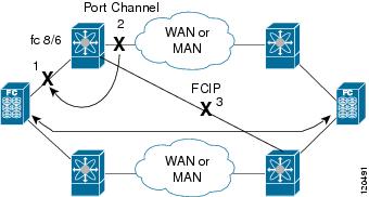
In Figure 9-2, only if both ISLs 2 and 3 fail, will the direct link 1 be brought down. Direct link 1 will not be brought down if either 2 or 3 are still functioning as desired.
Figure 9-2 Traffic Recovery Using Port Tracking
Tracking Multiple Ports
Detailed Steps
To track multiple ports, follow these steps:
|
|
|
|
|---|---|---|
Configures the specified interface and enters the interface configuration submode. You can now configure tracked ports. Note This link symbolizes the direct link (1) in Figure 9-2. |
||
Tracks interface fc8/6 with interface port-channel 1. When port-channel 1 goes down, interface fc8/6 is also brought down. Note This link symbolizes the ISL (2) in Figure 9-2. |
||
Tracks interface fc8/6 with interface fcip 5. When FCIP 5 goes down, interface fc8/6 is also brought down. Note This link symbolizes the ISL (3) in Figure 9-2. |
Information About Monitoring Ports in a VSAN
You can optionally configure one VSAN from the set of all operational VSANs on the tracked port with the linked port by specifying the required VSAN. This level of flexibility provides higher granularity in tracked ports. In some cases, when a tracked port is a TE port, the set of operational VSANs on the port can change dynamically without bringing down the operational state of the port. In such cases, the port VSAN of the linked port can be monitored on the set of operational VSANs on the tracked port.
If you configure this feature, the linked port is up only when the VSAN is up on the tracked port.

Tip![]() The specified VSAN does not have to be the same as the port VSAN of the linked port.
The specified VSAN does not have to be the same as the port VSAN of the linked port.
Monitoring Ports in a VSAN
Detailed Steps
To monitor a tracked port in a specific VSAN, follow these steps:
Information AboutForceful Shutdown
If a tracked port flaps frequently, then tracking ports using the operational binding feature may cause frequent topology change. In this case, you may choose to keep the port in the down state until you are able to resolve the reason for these frequent flaps. Keeping the flapping port in the down state forces the traffic to flow through the redundant path until the primary tracked port problems are resolved. When the problems are resolved and the tracked port is back up, you can explicitly enable the interface.
Tip![]() If you configure this feature, the linked port continues to remain in the shutdown state even after the tracked port comes back up. You must explicitly remove the forced shut state (by administratively bringing up this interface) of the linked port once the tracked port is up and stable.
If you configure this feature, the linked port continues to remain in the shutdown state even after the tracked port comes back up. You must explicitly remove the forced shut state (by administratively bringing up this interface) of the linked port once the tracked port is up and stable.
Forcefully Shutting Down a Tracked Port
Detailed Steps
To forcefully shut down a tracked port, follow these steps:
|
|
|
|
|---|---|---|
Configures the specified interface and enters the interface configuration submode. You can now configure tracked ports. |
||
Removes the port shutdown configuration for the tracked port. |
Displaying Port Tracking Information
Examples
The show commands display the current port tracking settings for the Cisco MDS switch (see Examples 9-1 to 9-4 ).
Example 9-1 Displays the Linked and Tracked Port Configuration
Example 9-2 Displays a Tracked Port Configuration for a Fibre Channel Interface
Example 9-3 Displays a Tracked Port Configuration for a PortChannel Interface
Example 9-4 Displays a Forced Shutdown Configuration
 Feedback