Overview of Cisco MDS 9148V-K9 Switch

The Cisco MDS 9148V-K9 switch has 48 x 8/16/32/64-Gbps multispeed ports and is a powerful and compact 1-rack unit (1 RU) SAN fabric switch. This switch has the following major features:

  • Provides consistent 64-Gbps quality performance for every Fibre Channel port on the switch.

  • Provides availability and reliability similar to the previous generations of the Cisco MDS9000 Series switches. Additionally, port channel link members can be distributed across the two 24-port port groups providing increased hardware level high availability.

  • Supports twenty four 64-Gbps Fibre Channel ports in the base variant, which can be expanded in increments of 8 ports up to 48 ports. This allows four licence options of 24, 32, 40, and 48 ports.

  • Supports enterprise class features, such as Auto Zone, Smart Zoning, Slow Drain Detection and Isolation, Virtual SAN (VSAN) and Inter-VSAN routing (IVR).

  • Provides intelligent diagnostics tools such as Inter-Switch Link (ISL) diagnostics, HBA diagnostics with leading HBA vendors, collection of remote transceiver error statistics, protocol decoding, network analysis tools, and integrated Cisco Call Home.

  • Supports Virtual Machine Identifier (VMID) that provides visibility into virtual machines that are accessing the storage devices in the fabric.

  • Supports HTTP based Cisco NX-API for RPC style on-switch command execution by remote scripts.

  • Provides secured hardware that protects the switch from malicious attacks by securing access to critical components such as the bootloader, system image loader, and Joint Test Action Group (JTAG) interface.

This chapter contains the following topics:

Chassis Components

This section describes the different components of the chassis.

Front View

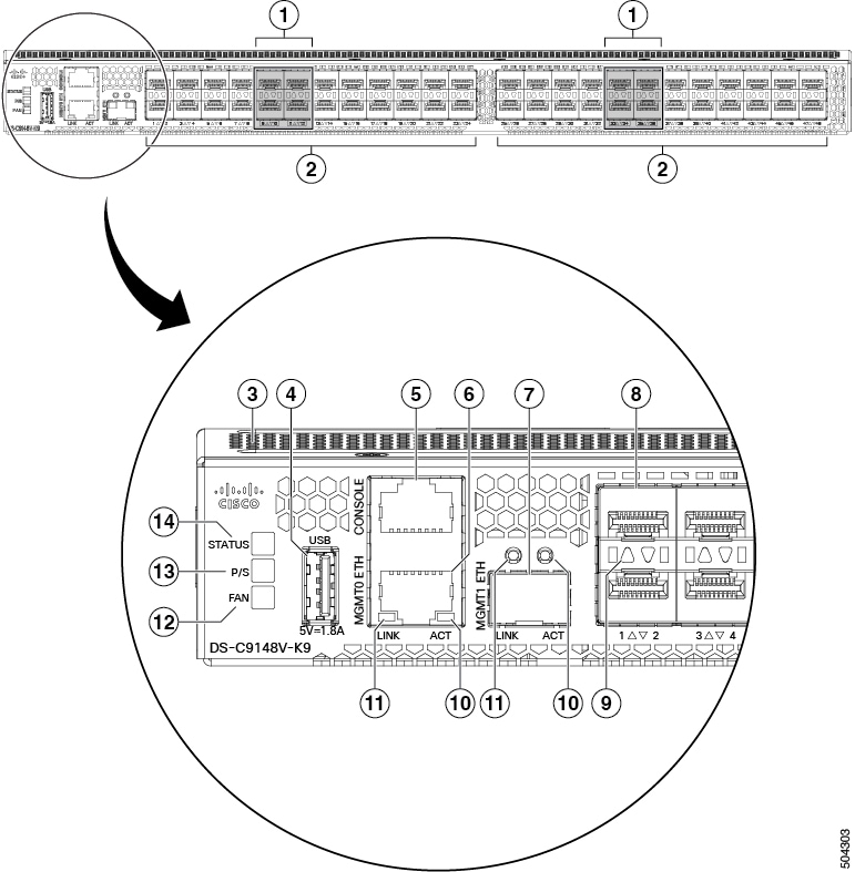
The following figure shows the front view of the switch:

Figure 1. Front View of the Switch

1

Fibre Channel encryption ports (9-12) and (33-36)

8

Fixed FC ports (48 x 8/16/32/64 Gbps, pluggable SFP or SFP+ compatible)

2

Fibre Channel port groups. A port group consists of 24 ports.

9

FC port status LEDs (48)

3

Airflow grill

10

Management port packet activity LEDs (2)

4

slot0 USB3 port

11

Management port link status LEDs (2)

5

RS232 serial console port (fixed RJ45 connector)

12

Fan status LED

6

mgmt0 Ethernet out of band management port (10/100/1000Base-T, fixed RJ45 connector)

13

Power status LED

7

mgmt1 Ethernet out of band analytics port

Note: The MGMT1 ETH port is not yet supported.

14

System status LED

Rear View

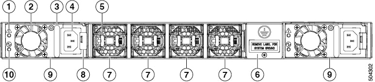
The following figure shows the rear view of the switch:

Figure 2. Rear View of the Switch

1

Power supply failure status LED (1 per PSU)

6

Ground pad

2

Power supply unit fan (1 per PSU)

7

Chassis fan modules (4)

3

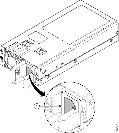
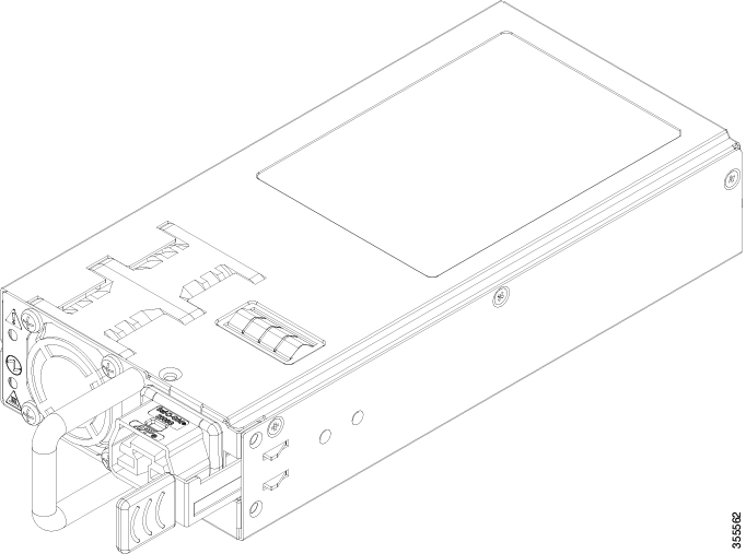
Power supply unit handle (1 per PSU)

8

Power supply unit latch release (1 per PSU)

4

Unswitched power socket (IEC C14, 1 per PSU)

9

Power supply units (2)

5

Chassis fan module release latches (2 per fan module)

10

Power supply status LED (1 per PSU)
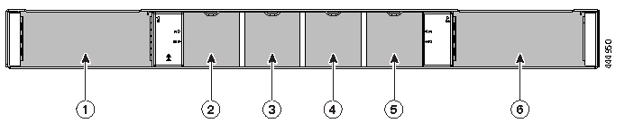
Figure 3. Rear Panel Slot Numbering of Cisco MDS 9148T

1

Power supply unit slot 1

4

Chassis fan module slot 3

2

Chassis fan module slot 1

5

Chassis fan module slot 4

3

Chassis fan module slot 2

6

Power supply unit slot 2

LEDs

The switch has LEDs on both the front and back of the switch to indicate the status of different system components during bootup tests and online operation. The following tables describe the location of each LED and the meaning of its color:

Table 1. Chassis Activity LEDs for the Switch

Indicator

Function

Color

Status

State

PWR: Power LED

(front panel of the chassis)

Chassis Power/Health

Off

Off

Either of the following conditions exists:

  • The system is not receiving sufficient power from the PSUs.

  • The operating system is not running.

Green

Solid On

Both PSUs are installed and operational.

Red

Solid On

Either of the following conditions exists:

  • A PSU has failed.

  • A PSU has been removed.

STATUS: Status LED

(front panel of the chassis)

System Status

Green

Solid On

All diagnostics have passed, Cisco NX-OS is running and the system is operational.

Orange

Solid On

Any of the following conditions exists:

  • The system is running bootup diagnostics.

  • The system is booting.

  • A minor temperature threshold is exceeded.

Red

Blinking

Mismatched airflow direction in one of the following modules:

  • Fan modules—The switch will shut down in 10-15 seconds.

  • PSUs—The switch will shut down after 10 minutes.

  • Fan modules and PSUs—The switch will shut down after 10 minutes.

Solid On

One of the following conditions exists:

  • A diagnostic test failed or another fault occurred during bootup.

  • A major temperature threshold is exceeded.

FAN: Fan status

(front panel of the chassis)

Fan Health

Green

Solid on

All chassis fan modules are operational.

Red

Solid on

A chassis fan module has failed.

PSU Voltage Status LED

(faceplate of each PSU)

Voltage Status

Green

Off

No input to the PSU.

Solid on

PSU output is OK.

Blinking

PSU output is not OK, but input is OK.

PSU Operation Status LED

(faceplate of each PSU)

Operation Status

Amber

Off

PSU is operating normally.

Solid on

One of the following conditions exists in the PSU:

Over voltage

Over current

Over temperature

Fan failure.

Blinking

PSU has a fault, but is still operational.

Unlabeled LED

(faceplate of each fan module)

Fan Operation Status

Green

Solid on

The chassis fan module is operating normally.

Amber

Solid on

The chassis fan in the fan module has failed.

The following table describes the Ethernet port LEDs for the switch.

LED Position

Status

State

Left

Off

There is no link.

Solid Green

Indicates a physical link.

Right

Solid Amber

There is no link traffic.

Blinking Amber

Indicates link traffic.

Off

There is no link.

The following table describes the Fibre Channel port LEDs for the switch.

Status

State

Solid Green

The link is up.

Regular Blinking Green

The link is up and the port beacon is active.

Intermittent Blinking Green

The link is up and traffic is flowing through the port.

Solid Orange

The link is disabled by the software.

Blinking Orange

A fault condition exists.

Off

No link.

Fan Modules

The fan modules have a fixed handle for insertion and removal from the chassis. The switch requires a minimum of two operating fan modules to prevent automatic shutdown. It supports up to four fan modules. This provides redundancy for uninterrupted operation in the event of fan module failure. The switch fan modules are hot-swappable to also allow swapping out of a fan module during operation for uninterrupted operation. During a fan module replacement, the internal airflow through the chassis is changed. If the internal airflow is disrupted for too long, the preset temperature thresholds will be exceeded and the system will automatically shut down to prevent permanent damage.

Figure 4. Fan Module

To facilitate different data center cooling configurations of hot or cold aisles and racks, there are two models of fan modules. The first type has airflow with port-side intake and exhaust at the rear of the chassis. The second type has airflow in the opposite direction, that is, rear-chassis intake and port-side exhaust. The airflow direction is denoted on each fan module as follows:

  • Red—Port-side intake airflow

  • Blue—Port-side exhaust airflow

For more information on installing and removing fan modules, see Installing and Removing Fan Modules.

Power Supplies

The switch PSUs have an unswitched power socket, a PSU status LED and a handle for insertion and removal of the PSU from the chassis. The switch requires a minimum of one operating PSU. It supports up to two PSUs. This provides redundancy for uninterrupted operation in the event of PSU or grid failure. The PSUs are hot-swappable to allow swapping out of a PSU during operation for uninterrupted operation. During a PSU replacement, the internal airflow through the chassis is changed. If the internal airflow is disrupted for too long, the preset temperature thresholds will be exceeded and the system will automatically shut down to prevent permanent damage.

Figure 5. 500-W Power Supply


To facilitate different data center cooling configurations of hot or cold aisles and racks, there are two models of PSUs. The first type has airflow with port-side intake and exhaust at the rear of the chassis. The second type has airflow in the opposite direction, that is, rear-chassis intake and port-side exhaust. The airflow direction is denoted on each PSU as follows:

  • Red—Port-side intake airflow

  • Blue—Port-side exhaust airflow

The switch supports PSUs of only one airflow type at a time. Both PSUs have to be either port-side exhaust, or port-side intake PSUs.


Note


The direction of PSU airflow must match the direction of the fan module airflow.


For more information on installing and removing PSUs, see Installing and Removing Power Supplies.

1200-W Power Supply

The Cisco MDS 9148V-K9 switch supports two hot swappable AC/ HVAC/ HVDC Bidirectional airflow power supply units (PSUs). Each unit has a power receptacle and a status LED on the faceplate, and a handle for inserting and removing the unit from the chassis. The Cisco MDS 9148V-K9 switch requires a minimum of 1 PSU for normal operation and 2 PSUs for normal operation with PSU redundancy. In the event of a PSU or AC supply (in grid redundant mode) failure, the system will continue to run. PSUs are hot swappable and can be individually replaced without shutting down the system. Procedures for installing and removing PSUs are detailed in the Installing and Removing Power Supplies section.

Figure 6. 1200-W Power Supply

The PSUs support bidirectional airflow (DS-CAC-1200W), port-side exhaust airflow and port-side intake airflow, of fan modules. The PSUs automatically configure themselves to work in port-side exhaust airflow mode if the switch has Blue system fan modules installed. Similarly, the PSU automatically configures itself to work in port-side intake airflow mode if the switch has Red fan modules installed. For more information on the direction of airflow in fan modules, see Fan Modules.