Cisco ACI Installation Guide for Red Hat OpenStack Using OSP Director

This chapter contains the following sections:

ACI with OpenStack Using OSP Director Overview

This document uses tripleo composable services that are introduced in the Newton release. This Cisco ACI Installation Guide for Red Hat OpenStack Using OSP Director, Release 2.3(x) or later document replaces the Cisco ACI Installation Guide for Red Hat OpenStack Using OSP Director, Release 2.2(x) and should be used for Releases 2.3 or later. For more information about composable services, see the OpenStack Composable Services Tutorial at:

https://docs.openstack.org/tripleo-docs/latest/install/developer/tht_walkthrough/tht_walkthrough.html

Cisco Application Centric Infrastructure (ACI) is a comprehensive policy-based architecture that provides an intelligent, controller-based network switching fabric. This fabric is designed to be programmatically managed through an API interface that can be directly integrated into multiple orchestration, automation, and management tools, including OpenStack. Integrating ACI with OpenStack allows dynamic creation of networking constructs to be driven directly from OpenStack requirements, while providing additional visibility within the ACI Application Policy Infrastructure Controller (APIC) down to the level of the individual virtual machine (VM) instance.

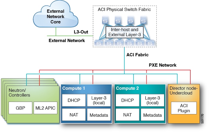
OpenStack defines a flexible software architecture for creating cloud-computing environments. The reference software-based implementation of OpenStack allows for multiple Layer 2 transports including VLAN, GRE, and VXLAN. The Neutron project within OpenStack can also provide software-based Layer-3 forwarding. When utilized with ACI, the ACI fabric provides an integrated Layer 2 and Layer 3 VXLAN-based overlay networking capability that can offload network encapsulation processing from the compute nodes onto the top-of-rack or ACI leaf switches. This architecture provides the flexibility of software overlay networking in conjunction with the performance and operational benefits of hardware-based networking.

The Cisco ACI OpenStack plugin can be used in either ML2 or GBP mode. In Modular Layer 2 (ML2) mode, a standard Neutron API is used to create networks. This is the traditional way of deploying VMs and services in OpenStack. In Group Based Policy (GBP) mode, a new API is provided to describe, create, and deploy applications as policy groups without worrying about network-specific details. Keep in mind that mixing GBP and Neutron APIs in a single OpenStack project is not supported. For more information, see the OpenStack Group-Based Policy User Guide at:

http://www.cisco.com/c/en/us/td/docs/switches/datacenter/aci/apic/sw/1-x/openstack/b_OpenStack_Group-Based_Policy_User_Guide.html

In previous OpFlex plugin versions (referred to as Classical mode), it was necessary to decide at the time of deployment if the mode of the plugin will be Neutron/ML2 or GBP, and it was not possible to use both GBP and Neutron/ML2 APIs at the same time. Starting from OpFlex plugin version 2.2.1. It is possible to deploy the plugin in “Unified” mode. In unified mode it is possible to create application topologies using either Neutron or GBP API. Unified plugin mode also requires OpenStack release Mitaka or later and ACI release 2.2(1) or later.

This guide covers deployment of the OpFlex plugins in Unified installation mode.


Note

While creating GBP groups in Unified mode, an (auto-ptg) group will also appear, these groups are for internal use and user interaction (attaching VM, adding members) is not supported.

Requirements and Prerequisites for Cisco ACI with OpenStack Using OSP Director

  • Target audience: You must have working knowledge of Linux, Red Hat OpenStack distribution, Cisco ACI policy model and GUI-based APIC configuration. Also familiarity with OpenStack architecture and deployment.

  • Cisco ACI fabric: Cisco ACI fabric is installed and initialized with the minimum supported version that is documented in the Cisco ACI Virtualization Compatibility Matrix. For basic guidelines on initializing a new Cisco ACI fabric, see the ACI Fabric Initialization Example, on page.


    Note

    For communication between multiple leaf pairs, the fabric must have a BGP route reflector enabled to use an OpenStack external network.
  • When using bonded fabric interface with vPC, adding the ovs_bond for the fabric interface is not supported because it must be added as a single interface to the ovs bridge. You must set the type to linux_bond for aggregating the fabric interfaces. Here is a rough example of how the fabric interface needs to be created in the nic-config templates:

    type: ovs_bridge
                  name: {get_input: bridge_name}
                  mtu: 1500
                  members:
                    -
                      type: linux_bond
                      name: bond1
                      ovs_options: {get_param: BondInterfaceOvsOptions}
                      mtu: 1600
                      members:
                        -
                          type: interface
                          name: nic1
                          primary: true
                          mtu: 1600
                        -
                          type: interface
                          name: nic2
                          mtu: 1600
  • When using bonding, only 802.3ad is supported.

  • When deploying with UCS-B series, only dual vNICs with bonding is supported for fabric interface for redundancy.


    Note

    Do not use a single vNIC with hardware failover.
  • In the Cisco APIC GUI, disable the OpFlex authentication in the fabric. Make sure "To enforce OpFlex client certificate authentication for GOLF and Linux." is not checked in System > System Settings > Fabric Wide Setting > Fabric Wide Setting Policy pane.

  • When you delete the Overcloud Heat stack, the Overcloud nodes are freed, but the Virtual Machine Manager (VMM) domain remains present in Cisco APIC. The VMM appears in Cisco APIC as a stale VMM domain along with the tenant unless you delete the VMM domain manually.

    Before you delete the VMM domain, verify that the stack has been deleted from the undercloud. Also check that any hypervisors appearing under the VMM domain are no longer in the connected state. Once both of these conditions are met, then you can safely delete the VMM domain from Cisco APIC.

Deploying OpFlex Using Unified Mode

This section describes how to install and configure the Cisco ACI OpenStack Plug-in on a Red Hat OpenStack distribution.

These example steps were validated on OpenStack Platform 10 releases of Red Hat OpenStack. OpenStack systems can vary widely in how they are installed. Therefore, you can adapt the example steps according to the specifics of your installation.

Follow the Red Hat OpenStack Platform Director installation document to prepare the OpenStack Platform Director and create the correct deployment and resource files.

For more information, see the Related Documentation.

Preparing ACI for OpenStack Installation

Setting Up the APIC and the Network

This section describes how to set up the Cisco APIC and the network.

Refer to the Network Planning section of the OpenStack Platform Director documentation for network layout such as the one shown in the figure below.

For more information, see Related Documentation.

Figure 1. A typical OpenStack Platform topology
Figure 2. A typical topology for installation of Red Hat OpenStack Platform 10 with the ACI plug-in
  • PXE Network is out-of-band (OOB) and uses a dedicated interface.

  • All OpenStack Platform (OSP) networks except for PXE are in-band (IB) through ACI.

    • API - VLAN 10

    • Storage - VLAN 11

    • StorageMgmt - VLAN 12

    • Tenant - VLAN 13

    • External - VLAN 14

    • ACI Infra - VLAN 4093

  • L3Out is pre-configured (In this example it is called L3-Out and EPG is L3-Out-EPG).

To prepare Cisco ACI for in-band configuration you can use the physical domain and the static binding to the endpoint groups (EPGs) created for these networks. This involves creating the required physical domain and attachable access entity profile (AEP). Important thing to note is that Infra VLAN should be enabled for the AEP. For more details, see:

http://www.cisco.com/c/en/us/td/docs/switches/datacenter/aci/apic/sw/kb/b_KB_Creating_AEP_Physical_Domains_VLANS_to_Deploy_an_EPG_on_a_Specific_Port.html

Procedure


Step 1

Log in to the Cisco APIC GUI and create a VLAN Pool for VLANs required for OpenStack Platform installation.

  1. On the menu bar, choose Fabric > Access Policies > Pools and right-click VLAN to create a VLAN Pool.

  2. In the Name field, enter the VLAN range namespace policy name (OSP8-infra).

  3. (Optional) In the Description field, enter the description of the VLAN range namespace policy.

  4. In the Encap Blocks section, click on the + icon to enter the encap block range.

  5. Click SUBMIT.

Step 2

Create an attachable entity profile and assign the above PhysDom to it. Also make sure Enable Infra VLAN is selected:

  1. On the menu bar, choose Fabric > Access Policies > Global Policies and right-click Attachable Access Entity Profile to create an attachable access entity profile.

  2. In the Name field, enter the name of the attachable access entity profile (OSP8-AEP).

  3. (Optional) In the Description field, enter the description of the attachable access entity profile.

  4. Check the Enable Infrastructure VLAN check box to enable the infrastructure VLAN.

  5. In the Domains (VMM, Physical or External) To Be Associated To Interfaces: section, click on the + icon, from the drop-down list, choose the domain profile and click Update.

  6. Click Next.

  7. Click Finish.

Step 3

Create a Physical Domain (PhysDom) and assign the VLAN pool to it.

  1. On the menu bar, choose Fabric > Access Policies > Physical and External Domains and right-click Physical Domains to create a Physical Domain.

  2. In the Name field, enter the name of the physical domain (OSP8-Phys).

  3. In the Associated Attachable Entity Profile field, choose an associated attachable entity profile.

  4. In the VLAN Pool field, choose a VLAN pool ([OSP8-infra-dynamic]).

  5. Click SUBMIT.

Step 4

In a separate tenant, you can also use Common to create an application profile (For example: OSP-8). Create the EPGs, bridge domains, and a VRF for the OSP Networks. If the PXE network is also going through ACI then also create EPG and BD for PXE (This is not shown in this example).

Step 5

Add static bindings (Paths) for the required VLANs. You have to expand the EPG to see the ":Static Binding Paths".

  1. Make sure the physical domain you created is attached to this EPG. You can add the physical domain using Application Profiles > EPG > EPG_name > Domains.

  2. On the menu bar, choose Tenants > Tenant common > Application Profiles > ACI-OSP8 > Application EPGs > EPG API > Static Binding Paths.

Step 6

Make sure the PhysDom is attached to the EPG.

Note 
Cisco ACI needs to be provisioned for networks mentioned above except for Tenant, External and Floating IP network. This involves creating the required phys-doms and attached entity profile. Important thing to note is that Infra VLAN should be enabled for the attached entity profile.
Cisco ACI should now be ready for OpenStack deployment.

Setting Up Overcloud

Follow the Red Hat OpenStack Platform Director installation document to prepare the OpenStack Platform Director and create the correct deployment and resource files.


Note

At the time of writing, the overcloud nodes try to resolve ipv6 DNS entries for localdomain, this can cause significant slowdown if the DNS server actually tries to resolve the name instead of sending the NXDomain. If you notice a significant slowdown, make sure that your DNS server is configured correctly.


Once the OpenStack Platform (OSP) Director is setup, you need to install the ACI TripleO orchestration before proceeding with deployment.

Preparing for ACI with OpFlex Orchestration

To install and enable ACI OpFlex on Overcloud, the following is a summary of steps that are required.

  • Modify the undercloud to include the necessary software packages.

  • Add to the Neutron puppet manifests, which are part of Overcloud image.

  • Add the OpFlex puppet manifests.

  • Modify some files on the undercloud tripleO infrastructure.

  • Create a HEAT environment file to provide ACI-related parameter values.

  • After the above modifications, Overcloud can be provisioned using the openstack overcloud deploy command and add the new environment file to the openstack overcloud deploy command.

Preparing Undercloud for Cisco ACI with OpFlex Orchestration

This section describes how to install integration package for Cisco ACI with OpFlex Orchestration.


Note

The following steps automatically create a local RPM repository on the undercloud, which will host Cisco ACI OpFlex RPM packages.

Procedure


Step 1

Log in to undercloud as user stack.

Step 2

Source the stackrc file.

Example:

$ source stackrc
Step 3

Download the latest ACI OSP (tripleo-ciscoaci) rpm from cisco.com.

For more information, see the APIC OpenStack Plugins.

Step 4

Install the rpm. This installs the dependencies. If the rpm is installed using the rpm command, some dependency may need to be manually installed.

Example:

$ sudo yum --nogpgcheck localinstall <rpm file>

Installing Overcloud

This section describes how to install Overcloud.

Procedure


Step 1

To use Cisco ACI certificate-based authentication, create a local user with a X.509 certificate.

Follow the procedure "Creating a Local User and Adding a User Certificate" in the Cisco APIC Security Configuration Guide, Release 4.2(x) .

Note 
When you use certificate-based authentication, make sure that the parameter ACIApicPassword is not specified.
Step 2

Copy the /opt/tripleo-ciscoaci/example_ciscoaci.yaml file to the /home/stack/templates/apic_gbp_config.yaml file. Edit the apic_gbp_config.yaml file and change the parameter_defaults to reflect the setup details.

parameter_defaults:   
NeutronCorePlugin: 'ml2plus'   
NeutronServicePlugins: 'group_policy,ncp,apic_aim_l3'   
NeutronEnableIsolatedMetadata: true   
EnablePackageInstall: true   
ACIYumRepo: http://10.10.250.10/acirepo  
ACIApicHosts: 172.31.218.136,172.31.218.137,172.31.218.138   
ACIApicUsername: admin   
ACIApicPassword: cisco123
ACIApicSystemId: osp10_cs   
ACIApicEntityProfile: f-aep   
ACIApicInfraVlan: 4093   
ACIApicInfraSubnetGateway: 10.0.0.30   
ACIApicInfraAnycastAddr: 10.0.0.32   
ACIOpflexUplinkInterface: nic2   
ACIOpflexEncapMode: vxlan   
ACIOpflexVlanRange: 1200:1300 
NeutronEnableForceMetadata: true
ACIOpflexBridgeToPatch: br-custom

Parameter

Description

ACIYumRepo: http://10.10.250.10/acirepo

Where the IP address is in the URL should be replaced with IP address of the director. This is where the OpFlex RPM will be installed from. The Repo is automatically created when tripleo_ciscoaci package is installed.

ACIApicHosts: 172.31.218.136,172.31.218.137,172.31.218.138

This lists the IP addresses or hostnames for the APICs.

ACIApicUsername: admin

This is the APIC username.

ACIApicPassword: cisco123

This is the APIC password.

ACIApicSystemId: osp10_cs

This should be a unique string to identify this particular OpenStack instance.

ACIApicEntityProfile: f-aep

This is the name of the AEP to attach the VMM domain in the ACI. This AEP needs to be created manually and should pre-exist before installing the Overcloud.

ACIApicInfraVlan: 4093

The ACI Infra VLAN is the OpFlex infra VLAN. It is picked during the ACI fabric initialization.

ACIApicInfraSubnetGateway: 10.0.0.30

This is the anycast IP address assigned to the SVI of the infra VLAN.

ACIApicInfraAnycastAddr: 10.0.0.32

This IP address matches the anycast IP address assigned to interface Loopback 1023 on the leaf switches.

ACIOpflexUplinkInterface: nic2

The interface is used for OpFlex. This is the fabric interface, it can be a individual or bonded interface. Follow the OSP director template guidelines for determining the interface name.

ACIOpflexEncapMode: vxlan

The encapsulation to be used between compute nodes and leaf switches is vxlan or vlan.

ACIOpflexVlanRange: 1200:1300

This is the VLAN range for encapsulation. Only needed when using the vlan encapsulation.

NeutronEnableForceMetadata: true

This is required to enable OpFlex optimized metadata.

ACIOpflexBridgeToPatch: br-custom

This parameter is only needed when using the VLAN encapsulation and customized templates. This parameter should be set to name of the bridge which is attached to the fabric uplink interface (or bond). The default bridge in Red Hat template is ‘br-ex’. If the default ‘br-ex’ is used for the deployment, this parameter is not needed. Otherwise set the value to the bridge name and a patch will be created between this bridge and integration bridge ‘br-int’.

ACIApicCertName

  • Value: Name of the Cisco APIC cert User (used for certificate-based authentication

  • Type: String

  • Default: None

  • Mandatory: No

ACIApicPrivateKey
  • Value: Private key for the cert User

  • Type: String

  • Default: None

  • Mandatory: No

ACIEnableBondWatchService

  • Value: True or False

  • Type: Boolean

  • Default: False

  • Comment Set this parameter to True if you use Cisco Unified Computing System (UCS) blade servers for OpenStack nodes.

AciKeystoneNotificationPurge

  • Value: True or False

  • Type: Boolean

  • Default: False

  • Comment Enables automatic purge of Cisco APIC tenants when the project is deleted in OpenStack.

Step 3

Edit the /home/stack/templates/network-environment.yaml file and set the following values:

NeutronEnableTunnelling: False
NeutronTunnelTypes: "''"
NeutronEnableL3Agent: False
NeutronEnableOVSAgent: False
Note 
These settings are necessary in order to make sure the default agents that are replaced by OpFlex agents are disabled. We recommend to keep these setting as indicated.
Step 4

Deploy Overcloud as described in the installation document.

For more information, see the Director Installation and Usage Red Hat OpenStack Platform, chapter 7.

  1. Deploy the new environment file created.

    Example:

    openstack overcloud deploy --templates -e  
    /usr/share/openstack-tripleo-heat-templates/environments/network-isolation.yaml -e
    ~/templates/network-environment.yaml  -e 
    ~/templates/apic_gbp_config.yaml
Step 5

On successful deployment, the appropriate VMM domain is created on Cisco APIC. Make sure to add this VMM domain to the right attached entity profile before creating OpenStack networks. If the attached entity profile is specified in the Cisco ACI yaml file using the parameter "ACIApicEntityProfile," this step is not required.

Step 6

Configuring multiple physnets and Hierarchical Port Binding (HPB).

It is now possible to deploy OSP with ACI, automatically configured for HPB and multiple physnets. The plug-in supports specification of multiple mechanism drives for HPB. The HPB requires pre-creation of physical domains in ACI per HPB physnet with VLAN pool for the NetworkVLANRanges for that particular physnet.

To specify physnet to physical interface or bond relationship:

You need to add the following parameters to the apic_gbp_config.yaml file as in step 1:

NeutronPhysicalDevMappings: physnet1:ens11,physnet2:ens7,physnet3:bond1
NeutronNetworkVLANRanges: physnet1:1200:1250,physnet2:1251:1300,physnet3:1301:1350
ACIMechanismDrivers: 'sriovnicswitch,apic_aim'

Parameter

Description

NeutronPhysicalDevMappings

This parameter specifies which interface belongs to which physnet. For this to work correctly APIC physdoms need to be pre-created with names prefixed with pdom_.

For example:

For physnet2, create a physdom with name pdom_physnet2.

NeutronNetworkVLANRanges

This lists the IP addresses or hostnames for the APICs.

ACIMechanismDrivers

The mechanism drivers to configure in ml2 configuration. For HPB to work correctly, the apic_aim should be the last one in the list.


ACI Fabric Initialization Example

This example solution is based on a basic Spine/Leaf switching fabric, installed with all defaults on the APIC configuration other than Fabric Name and controller IP addressing. Three APICs are used to form a highly available cluster. Each APIC is connected to one or more of the leaf switches in the fabric, it is best to use diverse leaf switches for connecting multiple APICs to provide higher availability of the controller services.

The switching system continues to forward traffic regardless of the presence of the APIC cluster. All configuration of the fabric is driven through the cluster so no configuration could be added, changed, or deleted without APIC connectivity in place. To ensure that administrative control of the fabric is not dependent on the fabric itself, an Out-Of-Band (OOB) network connection is needed on each of the APICs as shown in the Figure below:

Figure 3. APIC Cluster Connectivity

Procedure


Step 1

A good practice for setup of the ACI fabric is to make a note of the serial number of each of the switches in the fabric prior to discovering the fabric. Ideally, the console port of each of the switches is also connected to a terminal server so there is always administrative control regardless of the state of the ACI fabric. To recover the serial number when logged into a switch running an ACI software image, enter the show inventory command at the ACI switch CLI, noting the primary system serial number. This is the number that displays in the APIC during fabric discovery, allowing you to assign the correct name and node numbering in your scheme to the devices.

Step 2

To allow the APIC to discover and register the switches in the fabric, log in to the APIC GUI (Advanced mode).

  1. On the menu bar, choose Fabric > Inventory.

  2. In the Navigation pane, choose FabricMembership.

  3. In the Work pane, you should see an entry for the first switch discovered by the APIC.

  4. Verify this is the expected first switch for the first APIC in the cluster based on serial number.

  5. In the Work pane, choose the switch, right-click and choose Register Switch.

    Note 

    Assign logical numeric node IDs and node names that make sense for future troubleshooting, and Virtual Port Channel (vPC) pairing plans. For example, Node IDs 101/102 for the first two leaf switches, to be named leaf1/leaf2.

Step 3

Once the first leaf is discovered, the system will pass through that leaf to discover the spine switches, and then use the spine switches to discover remaining leaf switches. Register the additional nodes assigning logical node ID numbers and names according to the spine/leaf fabric layout.

Step 4

Confirm visually that the topology is discovered and physically connected as expected, perform the following actions:

  1. On the menu bar, choose Fabric > Inventory.

  2. In the Navigation pane, choose Topology.

    Figure 4. Discovered Spine/Leaf Topology
  3. Once the fabric is discovered, choose Admin > Firmware and validate the firmware versions running on all APICs, and fabric nodes (switches). If needed, upgrade to current or consistent versions before beginning initial configuration.