Fabric and Interface Configuration
To form the ACI fabric, Cisco Nexus 9000 Series ACI-mode switches are deployed in a leaf and spine topology managed by the APIC controller. Each leaf node is connected to all spine nodes with no connectivity between the leaf nodes. The interconnecting links between the leaf and spine nodes are called fabric links and the respective ports are called fabric ports. The fabric ports do not require user configuration for normal operation as these are auto discovered and factory default configuration is applied during fabric bring-up. All endpoint devices are connected to the leaf nodes through access ports. The access ports must be configured similar to those in NX-OS switches. Both fabric and access ports are represented as Interfaces as in NX-OS.
 Note |
Configuring FEX connections with FEX IDs |
As of Cisco APIC, Release 3.0(1k), connections to FEX modules can be configured as profiles.
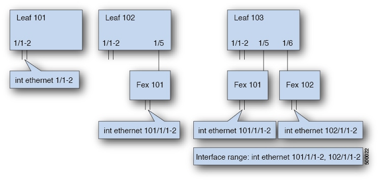
Interface Naming for Leaf and FEX Interfaces
In ACI fabric, most interface configuration is done for physical ports, port-channels, or vPCs (either directly connected to leaf nodes or connected through FEX modules). The general command syntax for each interface type is shown in the following table.
|
Interface Type |
Command Syntax |
Examples |
|---|---|---|
|
Port |
interface ethernet slot/port |
interface eth 1/1 |
|
FEX Port |
interface ethernet fex-id/slot/port |
interface eth 101/1/1 |
|
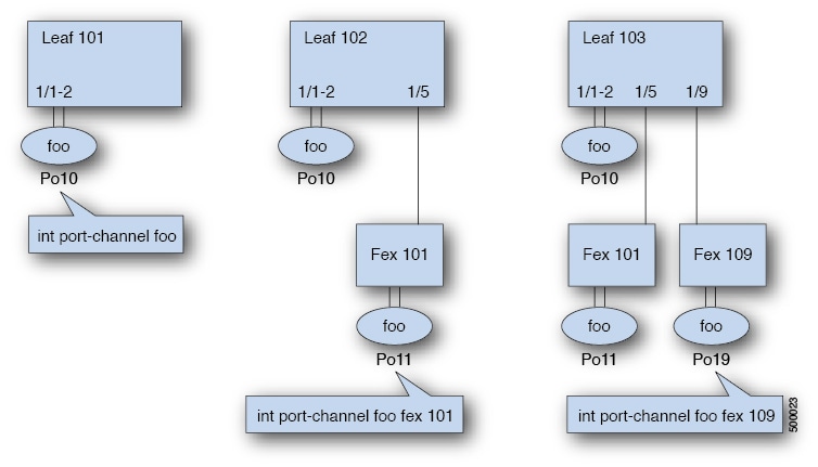
Port-channel |
interface port-channel name |
interface port-channel foo |
|
FEX Port-channel |
interface port-channel name fex fex-id |
interface port-channel foo fex 101 |
|
Virtual Port-channel (VPC) |
interface vpc name |
interface vpc foo |
|
vPC over FEX |
interface vpc name fex fex-a fex-b |
interface vpc foo fex 101 102 |
 Feedback