Overview
Cisco Application Policy Infrastructure Controller (APIC) release 6.1(4) added support for the Cisco APIC G5 Server.
Cisco APIC G5 Server—Small form-factor (SFF) drives, with 10-drive NVMe SSD HD back-plane, front panel configuration.
The documentation set for this product strives to use bias-free language. For the purposes of this documentation set, bias-free is defined as language that does not imply discrimination based on age, disability, gender, racial identity, ethnic identity, sexual orientation, socioeconomic status, and intersectionality. Exceptions may be present in the documentation due to language that is hardcoded in the user interfaces of the product software, language used based on RFP documentation, or language that is used by a referenced third-party product. Learn more about how Cisco is using Inclusive Language.
Cisco Application Policy Infrastructure Controller (APIC) release 6.1(4) added support for the Cisco APIC G5 Server.
Cisco APIC G5 Server—Small form-factor (SFF) drives, with 10-drive NVMe SSD HD back-plane, front panel configuration.
The Cisco Application Policy Infrastructure Controller (APIC) G5 Server has these considerations and restrictions:
The role of the Dual 1-Gb/10-Gb Ethernet ports (LAN1 and LAN2) in previous Cisco APIC Generations is now moved to the mLOM card and Ports available on that card.
The mLOM numbering doesn’t matter; APIC software creates a bond interface automatically.
 Note |
There is also an internal M.2 480G SSD boot disk. |
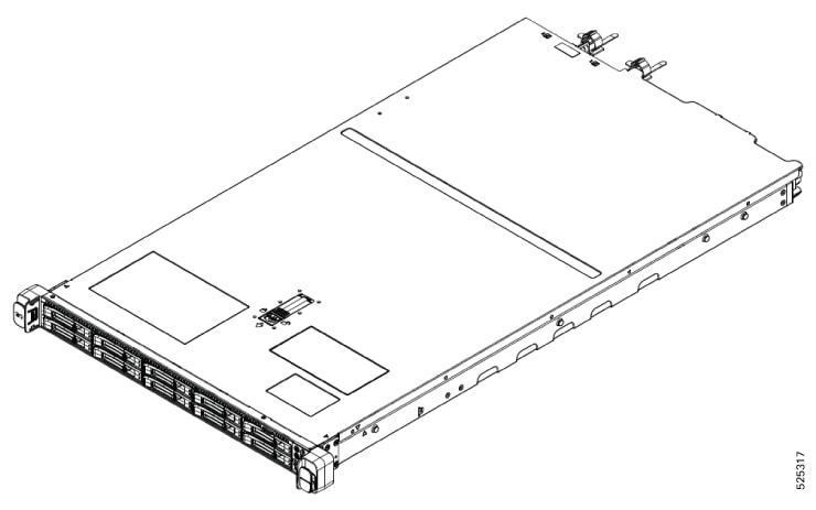
This topic shows the external features of the server versions.
The figure shows the APIC G5 server.
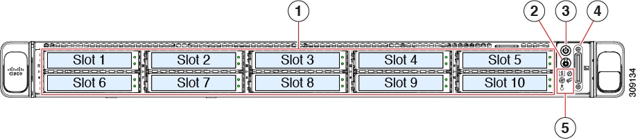
The figure shows the front panel features of the small form-factor drive versions of the server.
|
1 |
As an option, drive bays 1-10 can contain an NVMe drive each. APIC-G5-Server: Drive bays 1 and 2 support NVMe PCIe SSDs. |
2 |
Unit identification button/LED |
3 |
Power button/power status LED |
| 4 |
KVM connector (used with KVM cable that provides one DB-15 VGA, one DB-9 serial, and two USB 2.0 connectors) |
5 |
System LED cluster:
|
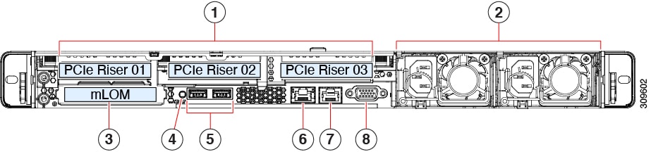
The rear panel features are the same for all versions of the server.
|
1 |
PCIe slots This is used for fabric connectivity. These PCIe Riser combinations are available:
One of these network interface cards should be installed in PCIe slot 1:
|
||
|
2 |
Power supply units (PSUs), two which can be redundant when configured in 1+1 power mode. |
3 |
Modular LAN-on-motherboard (mLOM) card bay (x16 PCIe lane). This is used for OOB management. Dual 1-Gb/10-Gb Ethernet ports (LAN1 and LAN2) The dual LAN ports can support 1 Gbps and 10 Gbps, depending on the link partner capability |
|
4 |
System identification button/LED |
5 |
USB 3.0 ports (two) |
|
6 |
Dedicated 1 GB Ethernet management port. This is used for CIMC management. |
7 |
COM port (RJ-45 connector) |
|
8 |
VGA video port (DB-15 connector) |
||
10/25GbE ports on Cisco UCS VIC 15425 Quad Port 10/25/50G CNA PCIE (UCSC-P-V5Q50G-D) can be used as either 10G or 25G ports. All ports must have the same speed.
The UCSC-P-V5Q50G-D supports 10G Base-T connectivity to the Cisco ACI TOR switch.
NIC supports SFP-10G-T-X for 10G Base-T connectivity to the Cisco ACI TOR switch.
Configure CL74 FEC in CIMC for bringing up the link between APIC-G5 and a leaf switch.
For a list of the 10G and 25G transceivers that are compatible with the APIC G5 server, please see Cisco Optics-to-Device Compatibility Matrix.
Note |
50G optics are not supported on APIC-G5 Cisco VIC 15425. Only 10G and 25G variants are supported for connections from APIC-G5 Cisco VIC 15425 to a leaf switch. |
|
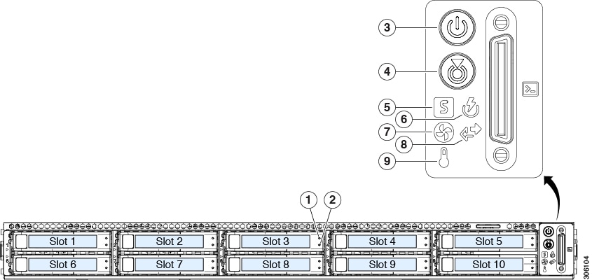
LED Name |
States |
|||
|
1 U.3 |
U.3 drive fault
|
|
||
|
2 U.3 |
U.3 drive activity LED |
|
||
|
3 |
Power button/LED |
|
||
|
4 |
Unit identification |
|
||
|
5 |
System health |
|
||
|
6 |
Power supply status |
|
||
|
7 |
Fan status |
|
||
|
8 |
Network link activity |
|
||
|
9 |
Temperature status |
|
|
LED Name |
States |
|
|---|---|---|
|
4 |
System Identification LED |
|
|
Power supply status (one LED each power supply unit) |
AC power supplies:
DC power supplies:
|
The server has internal fault LEDs for CPUs, DIMMs, and fan modules.
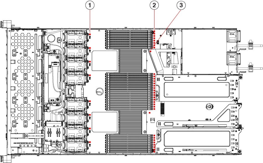
| Callout | Description |
|---|---|
|
1 |
Fan module fault LEDs (one behind each fan connector on the motherboard)
|
|
2 |
DIMM fault LEDs (one behind each DIMM socket on the motherboard) These LEDs operate only when the server is in standby power mode.
|
|
3 |
CPU fault LEDs (one behind each CPU socket on the motherboard). These LEDs operate only when the server is in standby power mode.
|
The table lists a summary of server features.
|
Feature |
Description |
||
|---|---|---|---|
|
Chassis |
One rack-unit (1RU) chassis |
||
|
Central Processor |
1x AMD EPYC 9354P 32-Core Processor |
||
|
Memory |
8x 32GB DDR5 5600 MHZ, total memory of the server is 256GB, with support for RDIMMs |
||
|
Multi-bit error protection |
Multi-bit error protection is supported |
||
|
Video |
The Cisco Integrated Management Controller (CIMC) provides video using the Matrox G200e video/graphics controller:
|
||
|
Baseboard management |
BMC, running Cisco Integrated Management Controller (Cisco IMC) firmware. Depending on your Cisco IMC settings, Cisco IMC can be accessed through the 1-Gb dedicated management port, the 1-Gb/10-Gb Ethernet LAN ports, or a Cisco virtual interface card. |
||
|
Network and management I/O |
Rear panel:
Front panel:
|
||
|
Modular LAN on Motherboard (mLOM)/ OCP3 3.0 slot |
The dedicated mLOM/OCP 3.0 slot on the motherboard can flexibly accommodate these cards:
|
||
|
WoL |
The two 1-Gb/10-Gb BASE-T Ethernet LAN ports support the wake-on-LAN (WoL) standard. |
||
|
Power |
Two of these hot-swappable power supplies:
One power supply is mandatory; add one more for 1 + 1 redundancy.
|
||
|
ACPI |
The advanced configuration and power interface (ACPI) 4.0 standard is supported. |
||
|
Front Panel |
The front panel controller provides status indications and control buttons |
||
|
Cooling |
Eight hot-swappable fan modules for front-to-rear cooling. |
||
|
PCIe I/O |
Horizontal PCIe expansion slots are supported by PCIe riser assemblies. The server supports either of the following configurations:
|
||
|
InfiniBand |
The PCIe bus slots in this server support the InfiniBand architecture. |
||
| Expansion Slots |
Three half-height riser slots
Two full-height riser slots
|
||
|
Interfaces |
Rear panel:
Front panel:
|
||
|
Storage, internal |
The server has these internal storage options:
|
||
|
Integrated Management Processor |
Baseboard Management Controller (BMC) running Cisco Integrated Management Controller (CIMC) firmware. Depending on your CIMC settings, the CIMC can be accessed through the 1GE dedicated management port, the 1GE/10GE mLOM ports, or a Cisco virtual interface card (VIC). CIMC manages certain components within the server, such as the Cisco 12G U.3 host bust adapter (HBA). |
||
|
Storage Controllers |
The Cisco 12G U.3 NVMe SSD storage plugs into a dedicated slot. Only one of these can be used at a time.
|
||
|
Integrated video |
Integrated VGA video. |
||
|
Intersight |
Intersight provides server management capabilities |
 Feedback