Release Notes for Connected Grid Switch 2520, Release 12.2(53)EX
Available Languages
Table of Contents
Release Notes for the Cisco CGS 2520, Cisco IOS Release 12.2(53)EX
Device Manager System Requirements
Finding the Software Version and Feature Set
Upgrading a Switch by Using the CLI
Recovering from a Software Failure
Configuring the Device Manager and HTTP Server Interface
Authentication Manager Commands and Earlier 802.1x Commands
Corrections for the Getting Started Guide
Corrections for the CGS 2520 Switch Software Configuration Guide, 12.2(53)EX
Updates for the Hardware Installation Guide
Update for the “Overview” Chapter
Corrections for the “Power Supply Installation” Chapter
Updates for the “Switch Installation” Chapter
Corrections for the Regulatory and Compliance Guide
Obtaining Documentation, Obtaining Support, and Security Guidelines
Release Notes for the Cisco CGS 2520, Cisco IOS Release 12.2(53)EX
Last Updated: December 12, 2019
Cisco IOS Release 12.2(53)EX runs on the Cisco Connected Grid Switch (CGS) 2520.
These release notes include important information about Cisco IOS Release 12.2(53)EX and any limitations, restrictions, and caveats that apply to the releases. Verify that these release notes are correct for your switch:
- If you are installing a new switch, see the Cisco IOS release label on the rear panel of your switch.
- If your switch is on, use the show version privileged EXEC command. See the “Finding the Software Version and Feature Set” section.
- If you are upgrading to a new release, see the software upgrade filename for the software version. See the “Deciding Which Files to Use” section.
For the complete list of CGS 2520 switch documentation, see the “Related Documentation” section.
You can download the switch software from this site (registered Cisco.com users with a login password):
http://www.cisco.com/cisco/web/download/index.html
System Requirements
Hardware Supported
Model |
Description |
|---|---|
24 10/100 Fast Ethernet ports, 2 dual-purpose ports (2 10/100/1000BASE-T copper ports and 2 SFP1 module slots), and 2 AC- and DC-power-supply module slots. |
|
16 100BASE-FX SFP-module slots; 8 10/100 Fast Ethernet PoE2 ports, 2 dual-purpose ports (2 10/100/1000BASE-T copper ports and 2 SFP module slots), and 2 AC- and DC-power-supply module slots. |
|
SFP modules3 |
Rugged and Industrial SFP modules
|
| Note For power supply module descriptions and supported configurations on switch models, see the hardware installation guide. |

Note![]() This model number is referenced in the documentation but is not available:
This model number is referenced in the documentation but is not available:
PWR-RGD-LOW-DC (low-voltage DC power supply)
Upgrading the Switch Software
These are the procedures for downloading software. Before downloading software, read this section for important information:
- Finding the Software Version and Feature Set
- Deciding Which Files to Use
- Archiving Software Images
- Upgrading a Switch by Using the CLI
- Recovering from a Software Failure
Finding the Software Version and Feature Set
The Cisco IOS image is stored as a bin file in a directory that is named with the Cisco IOS release. A subdirectory contains the files needed for web management. The image is stored on the compact flash memory card.
You can use the show version privileged EXEC command to see the software version that is running on your switch. The second line of the display shows the version.
You can also use the dir filesystem : privileged EXEC command to see the directory names of other software images that you might have stored in flash memory. For example, use the dir flash: command to display the images in the flash memory.
Deciding Which Files to Use
The upgrade procedures in these release notes describe how to perform the upgrade by using a combined tar file. This file contains the Cisco IOS image file and the files needed for the embedded device manager. You must use the combined tar file to upgrade the switch through the device manager. To upgrade the switch through the command-line interface (CLI), use the tar file and the archive download-sw privileged EXEC command.
Table 3 lists the filenames for this software release.
If you download the IP services image and plan to use Layer 3 functionality, you must use the Switch Database Management (SDM) routing template. To see which template is currently active template, enter the show sdm prefer privileged EXEC command. If necessary, entering the sdm prefer global configuration command to change the SDM template to a specific template. For example, if the switch uses Layer 3 routing, change the SDM template from the default to the routing template.You will need to reload the switch for the new template to take effect.
Archiving Software Images
Before upgrading your switch software, make sure that you have archived copies of the current Cisco IOS release and the Cisco IOS release to which you are upgrading. You should keep these archived images until you have upgraded all devices in the network to the new Cisco IOS image and until you have verified that the new Cisco IOS image works properly in your network.
Cisco routinely removes old Cisco IOS versions from Cisco.com. See Product Bulletin 2863 for information:
http://www.cisco.com/en/US/prod/collateral/iosswrel/ps8802/ps6969/ps1835/prod_bulletin0900aecd80281c0e.html
You can copy the bin software image file on the flash memory to the appropriate TFTP directory on a host by using the copy flash: tftp: privileged EXEC command.
Note![]() Although you can copy any file on the flash memory to the TFTP server, it is time consuming to copy all of the HTML files in the tar file. We recommend that you download the tar file from Cisco.com and archive it on an internal host in your network.
Although you can copy any file on the flash memory to the TFTP server, it is time consuming to copy all of the HTML files in the tar file. We recommend that you download the tar file from Cisco.com and archive it on an internal host in your network.
You can also configure the switch as a TFTP server to copy files from one switch to another without using an external TFTP server by using the tftp-server global configuration command. For more information about the tftp-server command, see the “Basic File Transfer Services Commands” section of the Cisco IOS Configuration Fundamentals Command Reference, Release 12.2 :
http://www.cisco.com/en/US/docs/ios/fundamentals/command/reference/cf_t1.html
Upgrading a Switch by Using the CLI
This procedure is for copying the combined tar file to the switch. You copy the file to the switch from a TFTP server and extract the files. You can download an image file and replace or keep the current image.
Note![]() Make sure that the compact flash card is inserted into the switch before downloading the software.
Make sure that the compact flash card is inserted into the switch before downloading the software.
To download software, follow these steps:
Step 1![]() Use Table 3 to identify the file that you want to download.
Use Table 3 to identify the file that you want to download.
Step 2![]() Download the software image file. If you have a SmartNet support contract, go to this URL, and log in to download the appropriate files:
Download the software image file. If you have a SmartNet support contract, go to this URL, and log in to download the appropriate files:
http://www.cisco.com/kobayashi/sw-center/sw-lan.shtml
To download the image for a CGS 2520 switch, click Cisco CGS 2520 software. To obtain authorization and to download the cryptographic software files, click CGS 2520 3DES Cryptographic Software.
Step 3![]() Copy the image to the appropriate TFTP directory on the workstation, and make sure that the TFTP server is properly configured.
Copy the image to the appropriate TFTP directory on the workstation, and make sure that the TFTP server is properly configured.
For more information, see the Cisco CGS 2520 Software Configuration Guide.
Step 4![]() Log into the switch through the console port or a Telnet session.
Log into the switch through the console port or a Telnet session.
Step 5![]() (Optional) Ensure that you have IP connectivity to the TFTP server by entering this privileged EXEC command:
(Optional) Ensure that you have IP connectivity to the TFTP server by entering this privileged EXEC command:
For more information about assigning an IP address and default gateway to the switch, see the software configuration guide for this release.
Step 6![]() Download the image file from the TFTP server to the switch. If you are installing the same version of software that is currently on the switch, overwrite the current image by entering this privileged EXEC command:
Download the image file from the TFTP server to the switch. If you are installing the same version of software that is currently on the switch, overwrite the current image by entering this privileged EXEC command:
The /overwrite option overwrites the software image in flash memory with the downloaded one.
The /reload option reloads the system after downloading the image unless the configuration has been changed and not saved.
For // location, specify the IP address of the TFTP server.
For / directory / image-name .tar, specify the directory (optional) and the image to download. Directory and image names are case sensitive.
This example shows how to download an image from a TFTP server at 198.30.20.19 and to overwrite the image on the switch:
You can also download the image file from the TFTP server to the switch and keep the current image by replacing the /overwrite option with the /leave-old-sw option.
Installation Notes
You can assign IP information to your switch by using these methods:
- The Express Setup program, as described in the switch getting started guide.
- The CLI-based setup program, as described in the switch hardware installation guide.
- The DHCP-based autoconfiguration, as described in the switch software configuration guide.
- Manually assigning an IP address, as described in the switch software configuration guide.
Limitations and Restrictions
You should review this section before you begin working with the switch. These are known limitations that will not be fixed, and there is not always a workaround. Some features might not work as documented, and some features could be affected by recent changes to the switch hardware or software.
These Cisco IOS limitations apply to the CGS 2520:
Configuration
- When a switch starts, SFP ports can become active before the Cisco IOS software loading process is complete. Packets arriving at these ports before the switch software is completely loaded are lost. This is a hardware limitation when the switch uses small form-factor pluggable (SFP) modules with copper connections.
The workaround is to use switch ports other than those specified for redundancy and for applications that immediately detect active links. (CSCeh70503)
- The switch might display tracebacks similar to this example when an EtherChannel interface port-channel type changes from Layer 2 to Layer 3 or the reverse (CSCsh12472):
15:50:11: %COMMON_FIB-4-FIBNULLHWIDB: Missing hwidb for fibhwidb Port-channel1 (ifindex 1632) -Traceback= A585C B881B8 B891CC 2F4F70 5550E8 564EAC 851338 84AF0C 4CEB50 859DF4 A7BF28 A98260 882658 879A58
- A ciscoFlashMIBTrap message appears during switch startup. This does not affect switch functionality. (CSCsj46992)
- When the configuration file is removed from the switch and the switch is rebooted, port status for VLAN 1 and the management port (Fast Ethernet 0) is sometimes reported as
upand sometimes asdown, resulting in conflicts. This status depends on when you respond to the reboot query:
Would you like to enter the initial configuration dialog?
–![]() After a reboot if you wait until the Line Protocol status of VLAN 1 appears on the console before responding, VLAN 1 line status is always shown as
After a reboot if you wait until the Line Protocol status of VLAN 1 appears on the console before responding, VLAN 1 line status is always shown as down. This is the correct state.
–![]() The problem (VLAN 1 reporting
The problem (VLAN 1 reporting up) occurs if you respond to the query before VLAN 1 line status appears on the console.
The workaround is to wait for approximately 1 minute after rebooting and until the VLAN 1 interface line status appears on the console before you respond to the query. (CSCsl02680)
–![]() Two-link ports on the same switch are connected with a crossover cable.
Two-link ports on the same switch are connected with a crossover cable.
–![]() The switch is running Cisco IOS 12.2(53)EX or later.
The switch is running Cisco IOS 12.2(53)EX or later.
The workaround is to connect the two ports with a straight-through cable. (CSCsr41271)
IP
- The switch does not create an adjacent table entry when the ARP timeout value is 15 seconds and the ARP request times out.
The workaround is to not set an ARP timeout value lower than 120 seconds. (CSCea21674)
- When the rate of received DHCP requests exceeds 2,000 packets per minute for a long time, the response time might be slow when you are using the console.
The workaround is to use rate limiting on DHCP traffic to prevent a denial of service attack from occurring. (CSCea21674)
IP Telephony
- After you change the access VLAN on a port that has IEEE 802.1x enabled, the IP phone address is removed. Because learning is restricted on IEEE 802.1x-capable ports, it takes approximately 30 seconds before the address is relearned.
No workaround is necessary. (CSCea85312)
The workaround is to enable PoE and to configure the switch to recover from the PoE error-disabled state. (CSCsf32300)
Fallback Bridging
- If a bridge group contains a VLAN to which a static MAC address is configured, all non-IP traffic in the bridge group with this MAC address destination is sent to all ports in the bridge group.
The workaround is to remove the VLAN from the bridge group or to remove the static MAC address from the VLAN. (CSCdw81955)
- Known unicast (secured) addresses are flooded within a bridge group if secure addresses are learned or configured on a port and the VLAN on this port is part of a bridge group. Non-IP traffic destined to the secure addresses is flooded within the bridge group.
The workaround is to disable fallback bridging or to disable port security on all ports in all VLANs participating in fallback bridging. To remove an interface from a bridge group and to remove the bridge group, use the no bridge-group bridge-group interface configuration command. To disable port security on all ports in all VLANs participating in fallback bridging, use the no switchport port-security interface configuration command. (CSCdz80499)
Multicasting
- Nonreverse-path forwarded (RPF) IP multicast traffic to a group that is bridged in a VLAN is leaked onto a trunk port in the VLAN even if the port is not a member of the group in the VLAN, but it is a member of the group in another VLAN. Because unnecessary traffic is sent on the trunk port, it reduces the bandwidth of the port.
There is no workaround for this problem because non-RPF traffic is continuous in certain topologies. As long as the trunk port is a member of the group in at least one VLAN, this problem occurs for the non-RPF traffic. (CSCdu25219)
- When you use the ip access-group interface configuration command with a router access control list (ACL) to deny access to a group in a VLAN, multicast data to the group that is received in the VLAN is always flooded in the VLAN, regardless of IGMP group membership in the VLAN. This provides reachability to directly connected clients, if any, in the VLAN.
The workaround is to not apply a router ACL set to deny access to a VLAN interface. Apply the security through other means; for example, apply VLAN maps to the VLAN instead of using a router ACL for the group. (CSCdz86110)
- If IP routing is disabled and IP multicast routing is enabled, IGMP snooping floods multicast packets to all ports in a VLAN.
The workaround is to enable IP routing or to disable multicast routing on the switch. You can also use the ip igmp snooping querier global configuration command if IP multicast routing is enabled for queries on a multicast router port. (CSCsc02995)
Routing
- A route map that has an ACL with a Differentiated Services Code Point (DSCP) clause cannot be applied to a Layer 3 interface. The switch rejects this configuration and displays a message that the route map is unsupported.
There is no workaround. (CSCea52915)
–![]() Port security is enabled with the violation mode set to protected.
Port security is enabled with the violation mode set to protected.
–![]() The maximum number of secure addresses is less than the number of switches connected to the port.
The maximum number of secure addresses is less than the number of switches connected to the port.
–![]() There is a physical loop in the network through a switch whose MAC address has not been secured, and its BPDUs cause a secure violation.
There is a physical loop in the network through a switch whose MAC address has not been secured, and its BPDUs cause a secure violation.
The workaround is to change any one of the listed conditions. (CSCed53633)
SPAN and RSPAN
- An egress SPAN copy of routed unicast traffic might show an incorrect destination MAC address on both local and remote SPAN sessions. This limitation does not apply to bridged packets.
The workaround for local SPAN is to use the replicate option. For a remote SPAN session, there is no workaround. (CSCdy72835)
- Egress SPAN routed packets (both unicast and multicast) show the incorrect source MAC address. For remote SPAN packets, the source MAC address should be the MAC address of the egress VLAN, but instead the packet shows the MAC address of the RSPAN VLAN. For local SPAN packets with native encapsulation on the destination port, the packet shows the MAC address of VLAN 1. This problem does not appear with local SPAN when the encapsulation replicate option is used. This limitation does not apply to bridged packets.
The workaround is to use the encapsulate replicate keywords in the monitor session global configuration command. Otherwise, there is no workaround. (CSCdy81521)
- The egress SPAN data rate might degrade when fallback bridging or multicast routing is enabled. The amount of degradation depends on the processor loading. Typically, the switch can egress SPAN at up to 40,000 packets per second (64-byte packets). As long as the total traffic being monitored is below this limit, there is no degradation. However, if the traffic being monitored exceeds the limit, only a portion of the source stream is spanned. When this occurs, the following console message appears:
Decreased egress SPAN rate. In all cases, normal traffic is not affected; the degradation limits only how much of the original source stream can be egress spanned. If fallback bridging and multicast routing are disabled, egress SPAN is not degraded.
There is no workaround. If possible, disable fallback bridging and multicast routing. If possible, use ingress SPAN to observe the same traffic. (CSCeb01216)
- Some IGMP report and query packets with IP options might not be ingress-spanned. Packets that are susceptible to this problem are IGMP packets containing 4 bytes of IP options (IP header length of 24). An example of such packets would be IGMP reports and queries having the router alert IP option. Ingress-spanning of such packets is not accurate and can vary with the traffic rate. Typically, very few or none of these packets are spanned.
VLAN
- A CPUHOG message sometimes appears when you configure a private VLAN. Enable port security on one or more of the ports affected by the private VLAN configuration.
There is no workaround. (CSCed71422)
- When you apply a per-VLAN quality of service (QoS), per-port policer policy-map to a VLAN Switched Virtual Interface (SVI), the second-level (child) policy-map in use cannot be re-used by another policy-map.
The workaround is to define another policy-map name for the second-level policy-map with the same configuration to be used for another policy-map. (CSCef47377)
- When dynamic ARP inspection is configured on a VLAN, and the ARP traffic on a port in the VLAN is within the configured rate limit, the port might go into an error-disabled state.
The workaround is to configure the burst interval to more than 1 second. (CSCse06827)
Important Notes
- Configuring the Device Manager and HTTP Server Interface
- Authentication Manager Commands and Earlier 802.1x Commands
Configuring the Device Manager and HTTP Server Interface
- We recommend this browser setting to speed up the time needed to display the device manager from Microsoft Internet Explorer.
From Microsoft Internet Explorer:
1. Choose Tools > Internet Options.
2. Click Settings in the “Temporary Internet files” area.
3. From the Settings window, choose Automatically.
5. Click OK to exit the Internet Options window.
- The HTTP server interface must be enabled to display the device manager. By default, the HTTP server is disabled on the switch. Use the show running-config privileged EXEC command to see if the HTTP server is enabled or disabled.
Beginning in privileged EXEC mode, follow these steps to configure the HTTP server interface:
- The device manager uses the HTTP protocol (the default is port 80) and the default method of authentication (the enable password) to communicate with the switch through any of its Ethernet ports and to allow switch management from a standard web browser.
If you change the HTTP port, you must include the new port number when you enter the IP address in the browser Location or Address field (for example, http://10.1.126.45:184 where 184 is the new HTTP port number). You should write down the port number through which you are connected. Use care when changing the switch IP information.
If you are not using the default method of authentication (the enable password), you need to configure the HTTP server interface with the method of authentication used on the switch.
Beginning in privileged EXEC mode, follow these steps to configure the HTTP server interface:
Authentication Manager Commands and Earlier 802.1x Commands
The authentication manager commands provide the same functionality as earlier 802.1x commands.
Open Caveats
A valid recursive static IPv6 route might not be added to the IP routing table even if the specified next hop resolves to a valid IPv6 output interface in the default route. This occurs when the default route is removed from the IP routing table and then added to the table. The recursive status route might not be removed from the table and the restored with the default route updates.
The workaround is to configure the recursive static IPv6 route with a specific interface.
After the web-based authentication feature with the default settings sends an HTML login page to a user and authentication succeeds, web-based authentication might not send a Login-Successful HTML page to the host.
The workaround is to close and open the browser window several times.
When the switch receives more than 1000 IPv6 prefixes from the Border Gateway Protocol (BGP), the CPU utilization increases.
The switch fails when it adds IPv6 routes to the ternary content addressable memory (TCAM).
The workaround is to reload the switch by entering the reload privileged EXEC command.
When a default gateway connects the switch to a TFTP server in a different network segment and the switch receives messages from the server, an ARP entry for the server is added to the switch ARP cache. If you replace the default gateway with another one, the switch and replaced default gateway cannot communicate with the TFTP server until the nonstatic ARP entries time out.
The workaround is to use the clear arp-cache privileged EXEC command to remove all nonstatic entries from the ARP cache.
Resolved Caveat
A vulnerability in the Internet Group Management Protocol (IGMP) version 3 implementation of Cisco IOS Software and Cisco IOS XE Software allows a remote unauthenticated attacker to cause a reload of an affected device. Repeated attempts to exploit this vulnerability could result in a sustained denial of service (DoS) condition. Cisco has released free software updates that address this vulnerability.
This advisory is posted at http://www.cisco.com/warp/public/707/cisco-sa-20100922-igmp.shtml.
Note: The September 22, 2010, Cisco IOS Software Security Advisory bundled publication includes six Cisco Security Advisories. Five of the advisories address vulnerabilities in Cisco IOS Software, and one advisory addresses vulnerabilities in Cisco Unified Communications Manager. Each advisory lists the releases that correct the vulnerability or vulnerabilities detailed in the advisory. The table at the following URL lists releases that correct all Cisco IOS Software vulnerabilities that have been published on September 22, 2010, or earlier:
http://www.cisco.com/warp/public/707/cisco-sa-20100922-bundle.shtml
Individual publication links are in “Cisco Event Response: Semiannual Cisco IOS Software Security Advisory Bundled Publication” at the following link:
http://www.cisco.com/web/about/security/intelligence/Cisco_ERP_sep10.html
Documentation Updates
- Corrections for the Getting Started Guide
- Corrections for the CGS 2520 Switch Software Configuration Guide, 12.2(53)EX
- Updates for the Hardware Installation Guide
- Corrections for the Regulatory and Compliance Guide
Corrections for the Getting Started Guide
This is the updated information:
Use twisted-pair copper wire (14- to 18-AWG) long enough to connect from the power-input terminal to the power source.
For power source connections, use wires rated for at least 194°F (90°C).
Corrections for the CGS 2520 Switch Software Configuration Guide, 12.2(53)EX
MAB + NEAT is not supported as noted in the following section: “802.1x Supplicant and Authenticator Switches with Network Edge Access Topology (NEAT)”
Update for the “Overview” Chapter
For a list of the supported SFPs, see this URL:
http://www.cisco.com/en/US/docs/switches/connectedgrid/cgs2520/hardware/installation/guide/higoverview.html#wp1394699
Corrections for the “Power Supply Installation” Chapter
This is the updated information:
Use twisted-pair copper wire (14- to 18-AWG) long enough to connect from the power-input terminal to the power source.
For power source connections, use wires rated for at least 194°F (90°C).
Rack Mounting
The Cisco CGS 2520 switches use 23-inch and ESTI brackets in addition to 19-inch brackets. The instructions for installing the 19-inch brackets are in the switch hardware guide.
You can order the 23-inch and ESTI brackets:
Figure 1 Attaching Brackets for 23-Inch Racks
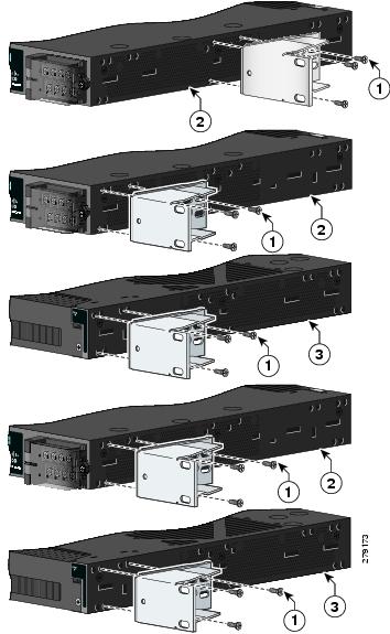
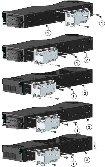
Figure 2 Attaching Brackets for ETSI Racks
For instructions on mounting the switch in rack:
http://www.cisco.com/en/US/docs/switches/connectedgrid/cgs2520/hardware/installation/guide/higinstall.html#wp1172376
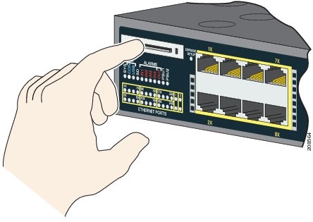
Replacing the SD Flash Memory Card
Step 1![]() Locate the SD flash memory card slot on the cable-side of the switch.
Locate the SD flash memory card slot on the cable-side of the switch.
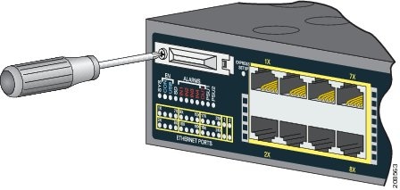
Step 2![]() Use a number-1 Phillips screwdriver to loosen the captive screw. See Figure 1-3.
Use a number-1 Phillips screwdriver to loosen the captive screw. See Figure 1-3.
Figure 1-3 Loosening the Captive Screw
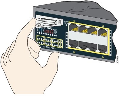
Step 3![]() Pull the cover open, and pull the cover tabs from the hinge. See Figure 1-4.
Pull the cover open, and pull the cover tabs from the hinge. See Figure 1-4.
Figure 1-4 Removing the SD Slot Cover
Step 4![]() Gently push the SD flash memory card to eject it out. See Figure 1-5. Place it in an antistatic bag to protect it from static discharge.
Gently push the SD flash memory card to eject it out. See Figure 1-5. Place it in an antistatic bag to protect it from static discharge.
Figure 1-5 Removing the SD Flash Memory Card
Step 5![]() Push the replacement card (upside down) into the slot, and press it firmly in place. The card is keyed so that you cannot insert it the wrong way.
Push the replacement card (upside down) into the slot, and press it firmly in place. The card is keyed so that you cannot insert it the wrong way.
Step 6![]() Place the SD slot cover tabs into the hinge.
Place the SD slot cover tabs into the hinge.
Step 7![]() Close the cover, and use a ratcheting torque number-1 Phillips screwdriver to torque the screw to
Close the cover, and use a ratcheting torque number-1 Phillips screwdriver to torque the screw to
4.5 in-lb.
Related Documentation
http://www.cisco.com/en/US/products/ps10978/tsd_products_support_series_home.html
- Cisco CGS 2520 Software Configuration Guide
- Cisco CGS 2520 Command Reference
- Cisco CGS 2520 System Message Guide
- Cisco CGS 2520 Hardware Installation Guide
- Cisco CGS 2520 Getting Started Guide —available in English, simplified Chinese, French, German, Italian, Japanese, Brazilian Portuguese, and Spanish
SFP module installation notes:
http://www.cisco.com/en/US/products/hw/modules/ps5455/prod_installation_guides_list.html
- Cisco Small Form-Factor Pluggable Modules Installation Notes
- Cisco CWDM GBIC and CWDM SFP Installation Note
Compatibility matrix documents:
http://www.cisco.com/en/US/products/hw/modules/ps5455/products_device_support_tables_list.html
Obtaining Documentation, Obtaining Support, and Security Guidelines
For information on obtaining documentation, submitting a service request, and gathering additional information, see the monthly What’s New in Cisco Product Documentation, which also lists all new and revised Cisco technical documentation:
http://www.cisco.com/en/US/docs/general/whatsnew/whatsnew.html
Subscribe to the What’s New in Cisco Product Documentation as a Really Simple Syndication (RSS) feed and set content to be delivered directly to your desktop using a reader application. The RSS feeds are a free service and Cisco currently supports RSS version 2.0.
This document is to be used in conjunction with the documents listed in the “Related Documentation” section.
 Feedback
Contact Cisco
- Open a Support Case

- (Requires a Cisco Service Contract)