- Overview
- Assigning the Switch IP Address and Default Gateway
- Configuring Switch Boot Optimization
- Administering the Switch
- Configuring the Switch Alarms
- Configuring SDM Templates
- Configuring Smartports Macros
- Configuring LLDP and LLDP-MED
- Configuring Port-Based Traffic Control
- Configuring CDP
- Configuring SPAN and RSPAN
- Configuring RMON
- Configuring System Message Logging
- Configuring SNMP
- Configuring Embedded Event Manager
- Configuring Cisco IOS IP SLAs Operations
- Configuring Ethernet OAM, CFM, and E-LMI
- Configuring Online Diagnostics
- Supported MIBs
Configuring the Switch Alarms
This chapter describes how to configure alarms on the Cisco Industrial Ethernet 2000U Series
(IE 2000U) and Connected Grid Switches, hereafter referred to as switch . This chapter includes the following sections:
- Information About Switch Alarms
- Prerequisites
- Guidelines and Limitations
- Default Settings
- Configuring External Alarms
- Configuring Switch Alarms
- Verifying Configuration
- Configuration Example
- Related Documents
- Feature History

Note![]() For complete syntax and usage information for the commands used in this chapter, see the switch command reference listed in the“Related Documents” section.
For complete syntax and usage information for the commands used in this chapter, see the switch command reference listed in the“Related Documents” section.
Note![]() For information about the alarm input and output ports, see theCisco IE 2000U Switch Hardware Installation Guide.
For information about the alarm input and output ports, see theCisco IE 2000U Switch Hardware Installation Guide.
Information About Switch Alarms
The switch software monitors switch conditions on a per-port or a switch basis. If the conditions present on the switch or a port do not match the set parameters, the switch software triggers an alarm or a system message. By default, the switch software sends the system messages to a system message logging facility, or a syslog facility. You can also configure the switch to send Simple Network Management Protocol (SNMP) traps to an SNMP server. You can configure the switch to trigger an external alarm device by using the alarm relay. For more information on how to configure the alarms, see the “Configuring Switch Alarms” section.
This section includes the following topics:
- Global Status Monitoring Alarms
- FCS Error Hysteresis Threshold
- Port Status Monitoring Alarms
- Triggering Alarm Options
Global Status Monitoring Alarms
The switch processes alarms related power supply conditions, referred to as global or facility alarms.
|
|
|
|---|---|
The switch monitors dual power supply levels. If there are two power supplies installed in the switch, an alarm triggers if a power supply fails. The alarm is automatically cleared when both power supplies are working. You can configure the power supply alarm to be connected to the hardware relays. For more information, see the “Configuring the Power Supply Alarms” section. |
FCS Error Hysteresis Threshold
The Ethernet standard calls for a maximum bit error rate of 10-8. On the switch, the bit error rate range is from 10-6 to 10-11. The bit error rate input to the switch is a positive exponent. If you want to configure the bit error rate of 10-9, enter the value 9 for the exponent. By default, the FCS bit error rate is 10-8.
You can set the FCS error hysteresis threshold to prevent the toggle of the alarm when the actual bit error rate fluctuates near the configured rate. The hysteresis threshold is defined as the ratio between the alarm clear threshold to the alarm set threshold, expressed as a percentage value.
For example, if the FCS bit error rate alarm value is configured to 10–8, that value is the alarm set threshold. To set the alarm clear threshold at 5*10-10, the hysteresis, value h , is determined as follows:
h = alarm clear threshold / alarm set threshold
h = 5*10-10 / 10-8 = 5*10-2 = 0.05 = 5 percent
The FCS hysteresis threshold is applied to all ports on the switch. The allowable range is from 1 to 10 percent. The default value is 10 percent. See the “Configuring the FCS Bit Error Rate Alarm” section for more information.
Port Status Monitoring Alarms
The switch can also monitor the status of the Ethernet ports and generate alarm messages based on the alarms listed in Table 5-2 . To save user time and effort, it supports changeable alarm configurations by using alarm profiles. You can create a number of profiles and assign one of these profiles to each Ethernet port.
Alarm profiles provide a mechanism for you to enable or disable alarm conditions for a port and associate the alarm conditions with one or both alarm relays. You can also use alarm profiles to set alarm conditions to send alarm traps to an SNMP server and system messages to a syslog server. The alarm profile defaultPort is applied to all interfaces in the factory configuration (by default).
Note![]() You can associate multiple alarms to one relay or one alarm to both relays.
You can associate multiple alarms to one relay or one alarm to both relays.
Table 5-2 lists the port status monitoring alarms and their descriptions and functions. Each fault condition is assigned a severity level based on the Cisco IOS System Error Message Severity Level.
|
|
|
|---|---|
The switch generates a link fault alarm when problems with a port physical layer cause unreliable data transmission. A typical link fault condition is loss of signal or clock. The link fault alarm is cleared automatically when the link fault condition is cleared. The severity for this alarm is error condition , level 3. |
|
The switch generates a port not forwarding alarm when a port is not forwarding packets. This alarm is cleared automatically when the port begins to forward packets. The severity for this alarm is warning , level 4. |
|
The switch generates a port not operating alarm when a port fails during the startup self-test. When triggered, the port not-operating alarm is only cleared when the switch is restarted and the port is operational. The severity for this alarm is error condition , level 3. |
|
The switch generates an FCS bit error rate alarm when the actual FCS bit error rate is close to the configured rate. You can set the FCS bit error rate by using the interface configuration CLI for each of the ports. See the “Configuring the FCS Bit Error Rate Alarm” section for more information. The severity for this alarm is error condition , level 3. |
Triggering Alarm Options
The switch supports these methods for triggering alarms:
The switch is equipped with one independent alarm relay that can be triggered by alarms for global and port status conditions. You can configure the relay to send a fault signal to an external alarm device, such as a bell, light, or other signaling device. You can associate any alarm condition with the alarm relay. Each fault condition is assigned a severity level based on the Cisco IOS System Error Message Severity Level.
See the “Configuring Switch Alarms” section for more information on configuring the relay.
SNMP is an application-layer protocol that provides a message format for communication between managers and agents. The SNMP system consists of an SNMP manager, an SNMP agent, and a management information base (MIB).
The snmp-server enable traps command can be changed so that the user can send alarm traps to an SNMP server. You can use alarm profiles to set environmental or port status alarm conditions to send SNMP alarm traps. See the “Enabling SNMP Traps” section for more information.
You can use alarm profiles to send system messages to a syslog server. See the “Configuring Switch Alarms” section for more information.
Prerequisites
Review the “Information About Switch Alarms” section.
Guidelines and Limitations
The snmp-server enable traps alarms command is used in conjunction with the snmp-server host command. Use the snmp-server host command to specify which host or hosts receive SNMP notifications. To send notifications, you must configure at least one snmp-server host command. See Chapter 14, “Configuring SNMP”.
Default Settings
|
|
|
|
|---|---|---|
Enabled in switch single power mode. No alarm. In dual-power supply mode, the default alarm notification is a system message to the console. |
||
Configuring External Alarms
You can connect up to four alarm inputs from external devices in your environment, such as a door, a temperature gauge, or a fire alarm, to the alarm input port on the switch front panel.
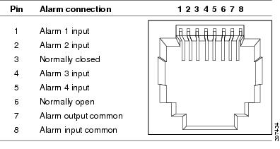
For each alarm input, you can configure an open or closed circuit to trigger an alarm and configure the severity of the alarm. A triggered alarm generates a system message. If you enter a descriptive name for the alarm, that name is included in the system message. A triggered alarm also turns on the LED display (the LED is normally off, meaning no alarm). See the Cisco IE 2000U Switch Hardware Installation Guide for information about the LEDs.
The alarm trigger setting is open or closed . If not set, the alarm is triggered when the circuit closes.
- Open means that the normal condition has current flowing through the contact (normally closed contact). The alarm is generated when the current stops flowing.
- Closed means that no current flows through the contact (normally open contact). The alarm is generated when current does flow.
You can set the alarm severity to minor , major , or critical . The severity is included in the alarm message and also sets the LED color when the alarm is triggered. The LED is amber for a minor alarm, red for a major alarm, and blinking red for a critical alarm. If not set, the default alarm severity is minor .
BEFORE YOU BEGIN
Review the “Global Status Monitoring Alarms” section.
DETAILED STEPS
|
|
|
|
|---|---|---|
(Optional) Configure a description for the alarm contact number. |
||
alarm contact { contact-number | all } { severity { critical | major | minor } | trigger { closed | open }} |
Configure the trigger and severity for an alarm contact number or for all contact numbers.
|
|
To delete the alarm description, enter the no alarm contact contact-number description privileged EXEC command. To set the alarm severity to minor (the default), enter the no alarm contact { contact-number | all } severity . To set the alarm contact trigger to closed (the default), enter the no alarm contact { contact-number | all } trigger.
To see the alarm configuration and status, enter the show env alarm-contact privileged EXEC command.
For more detailed information about the alarm commands, see the command reference listed in the “Related Documents” section.
Note![]() The switch supports the CISCO-ENTITY-ALARM-MIB for these alarms.
The switch supports the CISCO-ENTITY-ALARM-MIB for these alarms.
EXAMPLE
This example configures alarm input 2 named door sensor to assert a major alarm when the door circuit is closed and then displays the status and configuration for all alarms:
Configuring Switch Alarms
This section includes the following topics:
- Configuring the Power Supply Alarms
- Configuring the FCS Bit Error Rate Alarm
- Configuring Alarm Profiles
- Enabling SNMP Traps
Configuring the Power Supply Alarms
The presence of power supplies is dynamically detected. Use the show env power command in privileged EXEC or user EXEC mode to display power information for the switch.
Use the alarm facility power-supply rps global configuration command to associate the switch redundant power supply (RPS) alarm to the relay. You can also configure all alarms and traps associated with the RPS to be sent to syslog and the SNMP server.
BEFORE YOU BEGIN
Before you can use the notifies command to send alarm traps to an SNMP server, you must first set up the SNMP server by using the snmp-server enable traps alarms global configuration command. See the “Enabling SNMP Traps” section.
DETAILED STEPS
|
|
|
|
|---|---|---|
To disable sending the alarm to a relay, to syslog, or to an SNMP server, use the no alarm facility power-supply rps relay , no alarm facility power-supply rps notifies , or no alarm facility power-supply rps syslog global configuration commands.
EXAMPLE
This example sets the RPS monitoring alarm to the major relay:
Configuring the FCS Bit Error Rate Alarm
Setting the FCS Error Threshold
The switch generates an FCS bit error rate alarm when the actual rate is close to the configured rate. Use the fcs-threshold interface configuration command to set the FCS error threshold.
BEFORE YOU BEGIN
Review the “FCS Error Hysteresis Threshold” section.
DETAILED STEPS
|
|
|
|
|---|---|---|
Enter the interface to be configured, and enter interface configuration mode. |
||
| For value, the range is 6 to 11 to set a maximum bit error rate of 10-6 to 10-11. |
||
Use the no fcs-threshold interface configuration command to return to the default FCS threshold value.
EXAMPLE
This example shows how to set the FCS bit error rate for a port to 10-10:
Switch# configure terminal
Setting the FCS Error Hysteresis Threshold
The hysteresis setting prevents the toggle of an alarm when the actual bit error rate fluctuates near the configured rate. Use the alarm facility fcs-hysteresis global configuration command to set the FCS error hysteresis threshold.
Note![]() The FCS hysteresis threshold is applied to all ports of a switch.
The FCS hysteresis threshold is applied to all ports of a switch.
BEFORE YOU BEGIN
Review the “FCS Error Hysteresis Threshold” section.
DETAILED STEPS
|
|
|
|
|---|---|---|
Set the hysteresis percentage for the switch. For percentage, the range is 1 to 10. The default value is 10 percent. |
||
Use the no alarm facility fcs-hysteresis command to set the FCS error hysteresis threshold to its default value.
Note![]() Theshow running config command displays any FCS error hysteresis that is not the default value.
Theshow running config command displays any FCS error hysteresis that is not the default value.
EXAMPLE
This example shows how to set the FCS error hysteresis at 5 percent:
Configuring Alarm Profiles
Creating or Modifying an Alarm Profile
You can use the alarm profile global configuration command to create an alarm profile or to modify an existing profile. When you create a new alarm profile, none of the alarms are enabled.
Note![]() The only alarm enabled in thedefaultPort profile is the Port not operating alarm.
The only alarm enabled in thedefaultPort profile is the Port not operating alarm.
BEFORE YOU BEGIN
Before you use the notifies command to send alarm traps to an SNMP server, you must first set up the SNMP server by using the snmp-server enable traps alarms global configuration command. See the “Enabling SNMP Traps” section.
DETAILED STEPS
|
|
|
|
|---|---|---|
Create the new profile or identify an existing profile, and enter alarm profile configuration mode. |
||
Add or modify alarm parameters for a specific alarm (see Table 5-3 ). The values are 1 to 4. You can enter more than one alarm ID separated by a space. |
||
(Optional) Configure the alarm to send an SNMP trap to an SNMP server. |
||
(Optional) Configure the alarm to send an alarm trap to the relay. |
||
(Optional) Configure the alarm to send an alarm trap to a syslog server. |
||
To delete an alarm profile, use the no alarm profile name global configuration command.
Table 5-3 lists the alarmList IDs and their corresponding alarm definitions. For a description of these alarms, see the “Port Status Monitoring Alarms” section.
|
|
|
|---|---|
EXAMPLE
This example creates or modifies the alarm profile fastE for the Fast Ethernet port with link-down ( alarmList ID 3) alarm enabled. The link-down alarm is connected to the major relay. This alarm also send notifications to an SNMP server and sends system messages to a syslog server.
Attaching an Alarm Profile to a Specific Port
In interface configuration mode, you can use the alarm-profile command to attach an alarm profile to a specific port.
BEFORE YOU BEGIN
Review the “Port Status Monitoring Alarms” section.
DETAILED STEPS
|
|
|
|
|---|---|---|
Enter the number of the switch port to be configured, and the switch enters interface configuration mode. |
||
To detach an alarm profile from a specific port, use the no alarm-profile name interface configuration command.
EXAMPLE
This example attaches an alarm profile named fastE to a port:
This example detaches an alarm profile named fastE from a port:
Enabling SNMP Traps
Use the snmp-server enable traps alarms global configuration command to enable the switch to send alarm traps.
BEFORE YOU BEGIN
The snmp-server enable traps alarms command is used in conjunction with the snmp-server host command. Use the snmp-server host command to specify which host or hosts receive SNMP notifications. To send notifications, you must configure at least one snmp-server host command.
DETAILED STEPS
|
|
|
|
|---|---|---|
EXAMPLE
Verifying Configuration
|
|
|
|---|---|
Displays all alarm profiles in the system or a specified profile. |
|
Displays the status of environmental facilities on the switch. |
|
Configuration Example
This example configures alarm input 2 named door sensor to assert a major alarm when the door circuit is closed and then displays the status and configuration for all alarms:
This example sets the RPS monitoring alarm to the major relay:
This example shows how to set the FCS bit error rate for a port to 10-10:
Switch# configure terminal
This example shows how to set the FCS error hysteresis at 5 percent:
This example creates or modifies the alarm profile fastE for the Fast Ethernet port with link-down ( alarmList ID 3) alarm enabled. The link-down alarm is connected to the major relay. This alarm also send notifications to an SNMP server and sends system messages to a syslog server.
This example attaches an alarm profile named fastE to a port:
This example detaches an alarm profile named fastE from a port:
Related Documents
Feature History
|
|
|
|---|---|
 Feedback