Configuring HSRP
This chapter describes how to use the Cisco Hot Standby Router Protocol (HSRP) on the Cisco Industrial Ethernet 2000U Series Switches (IE 2000U) and Connected Grid switches, hereafter referred to as switch. HSRP provides routing redundancy for routing IP traffic without being dependent on the availability of any single router.
The switch must be running the IP services image to support HSRP.
Information About HSRP
HSRP is a standard method of providing high network availability by providing first-hop redundancy for IP hosts on an IEEE 802 LAN configured with a default gateway IP address. HSRP routes IP traffic without relying on the availability of any single router.
HSRP enables a set of router interfaces to work together to present the appearance of a single virtual router or default gateway to the hosts on a LAN. When you configure HSRP on a network or segment, it provides a virtual Media Access Control (MAC) address and an IP address that a group of configured routers share.
HSRP allows two or more HSRP-configured routers to use the MAC address and IP network address of a virtual router. The virtual router does not exist; rather, it represents the common target for routers that you configure to provide backup to each other. You configure one of the routers to be the active router and another to be the standby router, which assumes control of the group MAC address and IP address when the designated active router fails.

Note![]() Routers in an HSRP group can be any router interface that supports HSRP, including routed ports and switch virtual interfaces (SVIs) on the switch.
Routers in an HSRP group can be any router interface that supports HSRP, including routed ports and switch virtual interfaces (SVIs) on the switch.
HSRP provides high network availability by providing redundancy for IP traffic from hosts on networks. In a group of router interfaces, the active router is the router of choice for routing packets; and, the standby router is the router that takes over the routing duties when an active router fails or when preset conditions are met.
HSRP is useful for hosts that do not support a router discovery protocol and cannot switch to a new router when their selected router reloads or loses power. When HSRP is configured on a network segment, it provides a virtual MAC address and an IP address that is shared among router interfaces in a group of router interfaces running HSRP. The router selected by the protocol to be the active router receives and routes packets destined for the group’s MAC address. For n routers running HSRP, there are n +1 IP and MAC addresses assigned.
HSRP detects when the designated active router fails, and a selected standby router assumes control of MAC and IP addresses of the Hot Standby group. A new standby router is also selected at that time. Devices running HSRP send and receive multicast UDP-based hello packets to detect router failure and to designate active and standby routers. When HSRP is configured on an interface, Internet Control Message Protocol (ICMP) redirect messages are automatically enabled for the interface.
You can configure multiple Hot Standby groups among switches that are operating in Layer 3 to make more use of the redundant routers. To do so, specify a group number for each Hot Standby command group that you configure for an interface. For example, you might configure an interface on switch 1 as an active router and one on switch 2 as a standby router and also configure another interface on switch 2 as an active router with another interface on switch 1 as its standby router.
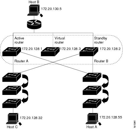
Figure 4-1 shows a segment of a network configured for HSRP. Each router is configured with the MAC address and IP network address of the virtual router. Instead of configuring hosts on the network with the IP address of Router A, you configure them with the IP address of the virtual router as their default router. When Host C sends packets to Host B, it sends them to the MAC address of the virtual router. If for any reason, Router A stops transferring packets, Router B responds to the virtual IP address and virtual MAC address and becomes the active router, assuming the active router duties. Host C continues to use the IP address of the virtual router to address packets destined for Host B, which Router B now receives and sends to Host B. Until Router A resumes operation, HSRP allows Router B to provide uninterrupted service to users on Host C’s segment that need to communicate with users on Host B’s segment and also continues to perform its normal function of handling packets between the Host A segment and Host B.
Figure 4-1 Typical HSRP Configuration
HSRP Versions
The switch supports these Hot Standby Router Protocol (HSRP) versions:
–![]() The HSRP group number can be from 0 to 255.
The HSRP group number can be from 0 to 255.
–![]() HSRPv1 uses the multicast address 224.0.0.2 to send hello packets, which can conflict with Cisco Group Management Protocol (CGMP) leave processing. You cannot enable HSRPv1 and CGMP at the same time; they are mutually exclusive.
HSRPv1 uses the multicast address 224.0.0.2 to send hello packets, which can conflict with Cisco Group Management Protocol (CGMP) leave processing. You cannot enable HSRPv1 and CGMP at the same time; they are mutually exclusive.
–![]() To match the HSRP group number to the VLAN ID of a subinterface, HSRPv2 can use a group number from 0 to 4095 and a MAC address from 0000.0C9F.F000 to 0000.0C9F.FFFF.
To match the HSRP group number to the VLAN ID of a subinterface, HSRPv2 can use a group number from 0 to 4095 and a MAC address from 0000.0C9F.F000 to 0000.0C9F.FFFF.
–![]() HSRPv2 uses the multicast address 224.0.0.102 to send hello packets. HSRPv2 and CGMP leave processing are no longer mutually exclusive, and both can be enabled at the same time.
HSRPv2 uses the multicast address 224.0.0.102 to send hello packets. HSRPv2 and CGMP leave processing are no longer mutually exclusive, and both can be enabled at the same time.
–![]() HSRPv2 has a different packet format than HRSPv1.
HSRPv2 has a different packet format than HRSPv1.
A switch running HSRPv1 cannot identify the physical router that sent a hello packet because the source MAC address of the router is the virtual MAC address.
HSRPv2 has a different packet format than HSRPv1. A HSRPv2 packet uses the type-length-value (TLV) format and has a 6-byte identifier field with the MAC address of the physical router that sent the packet.
If an interface running HSRPv1 gets an HSRPv2 packet, the type field is ignored.
HSRPv2 and HSRPv1 are mutually exclusive. HSRPv2 is not interoperable with HSRPv1 on an interface and the reverse.
Multiple HSRP
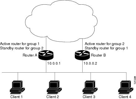
The switch supports Multiple HSRP (MHSRP), an extension of HSRP that allows load sharing between two or more HSRP groups. You can configure MHSRP to achieve load balancing and to use two or more standby groups (and paths) from a host network to a server network. In Figure 4-2, half the clients are configured for Router A, and half the clients are configured for Router B. Together, the configuration for Routers A and B establishes two HSRP groups. For group 1, Router A is the default active router because it has the assigned highest priority, and Router B is the standby router. For group 2, Router B is the default active router because it has the assigned highest priority, and Router A is the standby router. During normal operation, the two routers share the IP traffic load. When either router becomes unavailable, the other router becomes active and assumes the packet-transfer functions of the router that is unavailable.
See the “Enabling MHSRP” section for the example configuration steps.
Note![]() For MHSRP, you need to enter thestandby preempt interface configuration command on the HSRP interfaces so that if a router fails and then comes back up, preemption restores load sharing.
For MHSRP, you need to enter thestandby preempt interface configuration command on the HSRP interfaces so that if a router fails and then comes back up, preemption restores load sharing.
Prerequisites
Guidelines and Limitations
- You can configure HSRP on a maximum of 32 VLAN or routing interfaces.
- A specified interface must be one of these Layer 3 interfaces:
–![]() Routed port: a physical port configured as a Layer 3 port by entering the no switchport interface configuration command.
Routed port: a physical port configured as a Layer 3 port by entering the no switchport interface configuration command.
–![]() SVI: a VLAN interface created by using the interface vlan vlan_id global configuration command and by default a Layer 3 interface.
SVI: a VLAN interface created by using the interface vlan vlan_id global configuration command and by default a Layer 3 interface.
–![]() Etherchannel port channel in Layer 3 mode: a port-channel logical interface created by using the interface port-channel port- channel-number global configuration command and binding the Ethernet interface into the channel group. For more information, see the “Defining Layer 3 EtherChannels” section.
Etherchannel port channel in Layer 3 mode: a port-channel logical interface created by using the interface port-channel port- channel-number global configuration command and binding the Ethernet interface into the channel group. For more information, see the “Defining Layer 3 EtherChannels” section.
HSRPv1 and HSRPv2 on the Same Switch
- You configure HSRPv2 and HSRPv1 on the same switch when you configure HSRPv2 on different interfaces than those on which you configure HSRPv1.
- You can change the version of an HSRP group from HSRPv2 to HSRPv1 only when the group number is less than 256.
- If you change the HSRP version on an interface, each HSRP group resets because it now has a new virtual MAC address.
- Assigning a priority allows you to select the active and standby routers. If preemption is enabled, the router with the highest priority becomes the active router. If priorities are equal, the current active router does not change.
- The highest number (1 to 255) represents the highest priority (most likely to become the active router).
- When setting the priority, preempt, or both, you must specify at least one keyword ( priority , preempt , or both).
- The priority of the device can change dynamically if an interface is configured with the standby track command and another interface on the router goes down.
- The standby track interface configuration command ties the router hot standby priority to the availability of its interfaces and is useful for tracking interfaces that are not configured for HSRP. When a tracked interface fails, the hot standby priority on the device on which tracking has been configured decreases by 10. If an interface is not tracked, its state changes do not affect the hot standby priority of the configured device. For each interface configured for hot standby, you can configure a separate list of interfaces to be tracked.
- The standby track interface-priority interface configuration command specifies how much to decrement the hot standby priority when a tracked interface goes down. When the interface comes back up, the priority is incremented by the same amount.
- When multiple tracked interfaces are down and interface-priority values have been configured, the configured priority decrements are cumulative. If tracked interfaces that were not configured with priority values fail, the default decrement is 10, and it is noncumulative.
- When routing is first enabled for the interface, it does not have a complete routing table. If it is configured to preempt, it becomes the active router, even though it is unable to provide adequate routing services. To solve this problem, configure a delay time to allow the router to update its routing table.
HSRP Authentication and Timers
- The authentication string is sent unencrypted in all HSRP messages. You must configure the same authentication string on all routers and access servers on a cable to ensure interoperation. Authentication mismatch prevents a device from learning the designated Hot Standby IP address and timer values from other routers configured with HSRP.
- Routers or access servers on which standby timer values are not configured can learn timer values from the active or standby router. The timers configured on an active router always override any other timer settings.
- All routers in a Hot Standby group should use the same timer values. Normally, the holdtime is greater than or equal to 3 times the hellotime .
Default Settings
|
|
|
|---|---|
System assigned as: 0000.0c07.acXX, where XX is the HSRP group number |
|
Configuring HSRP
This section includes the following topics:
- Enabling HSRP
- Defining HSRP Priority
- Enabling MHSRP
- Defining HSRP Authentication and Timers
- Enabling HSRP Support for ICMP Redirect Messages
Enabling HSRP
Note The standby ip interface configuration command activates HSRP on the configured interface.
- When you specify an IP address, the router uses that address as the designated address for the Hot Standby group.
- When you do not specify an IP address, the router learns the address through the standby function.
You must configure at least one Layer 3 port on the LAN with the designated address. Configuring an IP address always overrides another designated address currently in use.
If you enable the standby ip command on a router interface and enable proxy ARP on that same interface, then proxy ARP requests are answered using the Hot Standby group MAC address when Hot Standby state is active on the interface. If the interface is in a different state, the router suppresses proxy ARP responses.
BEFORE YOU BEGIN
Review the Guidelines and Limitations for this feature. (See Guidelines and Limitations.)
DETAILED STEPS
EXAMPLE
This example shows how to activate HSRP for group 1 on an interface. The IP address used by the hot standby group is learned by using HSRP.
Defining HSRP Priority
HSRP Priority sets the characteristics for finding active and standby routers. It also defines the behavior for the standby router when it becomes the active router.
BEFORE YOU BEGIN
Review the HSRP Priority Guidelines and Limitations. (See Guidelines and Limitations.)
DETAILED STEPS
EXAMPLE
This example activates a port, sets an IP address and a priority of 120 (higher than the default value), and waits for 300 seconds (5 minutes) before attempting to become the active router:
Enabling MHSRP
To enable MHSRP and load balancing, you must configure two routers as active routers for their groups, with virtual routers as standby routers. This example shows how to enable the MHSRP configuration shown in Figure 4-2. You need to enter the standby preempt interface configuration command on each HSRP interface so that if a router fails and comes back up, the preemption occurs and restores load balancing.
Router A is configured as the active router for group 1, and Router B is configured as the active router for group 2. The HSRP interface for Router A has an IP address of 10.0.0.1 with a group 1 standby priority of 110 (the default is 100). The HSRP interface for Router B has an IP address of 10.0.0.2 with a group 2 standby priority of 110.
Group 1 uses a virtual IP address of 10.0.0.3 and group 2 uses a virtual IP address of 10.0.0.4.
Note![]() For detailed configuration steps, refer toEnabling HSRP and Defining HSRP Priority.
For detailed configuration steps, refer toEnabling HSRP and Defining HSRP Priority.
EXAMPLE
Defining HSRP Authentication and Timers
You can optionally configure an HSRP authentication string or change the hello-time interval and holdtime.
BEFORE YOU BEGIN
Review the HSRP Authentication and Timers Guidelines and Limitations. (See Guidelines and Limitations.)
DETAILED STEPS
EXAMPLE
This example shows how to configure word as the authentication string required to allow Hot Standby routers in group 1 to interoperate:
This example shows how to set the timers on standby group 1 with the time between hello packets at 5 seconds and the time after which a router is considered down to be 15 seconds:
Enabling HSRP Support for ICMP Redirect Messages
When you configure HSRP on an interface, the router automatically enables Internet Control Message Protocol (ICMP) redirect messages on those interfaces.
This feature filters outgoing ICMP redirect messages through HSRP, in which the next hop IP address might be changed to an HSRP virtual IP address. ICMP is a network layer Internet protocol that provides message packets to report errors and other information relevant to IP processing. ICMP provides diagnostic functions, such as sending and directing error packets to the host.
When the switch is running HSRP, make sure hosts do not discover the interface (or real) MAC addresses of routers in the HSRP group. If a host is redirected by ICMP to the real MAC address of a router and that router later fails, packets from the host are lost.
Verifying Configuration
This is a an example of output from the show standby privileged EXEC command, displaying HSRP information for two standby groups (group 1 and group 100):
Feature History
|
|
|
|---|---|
 Feedback