Cisco Smart+Connected Solutions with Signify Interact Office Wired Implementation Guide
The Cisco Smart+Connected Solutions with Signify Interact Office Wired system is an over-the-top (OTT) connected lighting system that uses Cisco's PoE switching products and the Signify Envision IP protocol to control networks of IP luminaires directly and to provide indoor lighting services on the enterprise network.
This document provides implementation and configuration details for the Cisco Smart+Connected Solutions with Signify Interact Office Wired system for the Signify network, as depicted in Figure 2.
Navigator
This document covers the following:
Audience and Scope
The audience of this guide comprises, but is not limited to, system architects, network/compute design engineers, systems engineers, field consultants, Cisco Advanced Services specialists, and customers. This document also provides high-level Signify Lighting use case implementation for the use cases defined in the design section for Signify Commissioning Engineers.
Detailed Signify Lighting use case implementation is beyond the scope of this document and it is the responsibility of Signify Commissioning Engineers to use appropriate Signify documentation that is referenced in this document.
Readers should be familiar with IPv4 and IPv6 dual stack networking concepts and protocols, Networking Layer 4 through Layer 7 services and Cisco Catalyst Series Switches, Cisco Unified Computing System (UCS), and VMware hypervisors.
Implementation Workflow
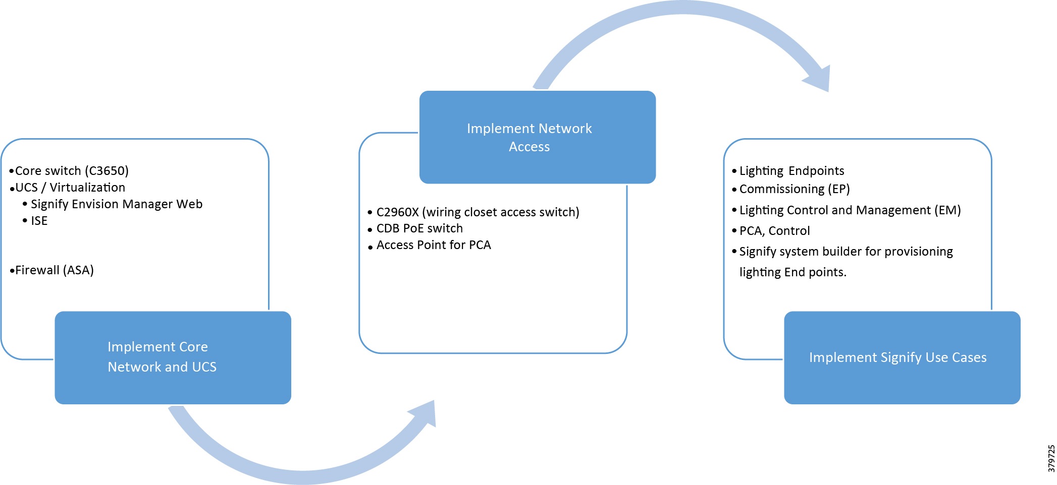
This section provides the high-level implementation flow for deploying the standalone Cisco Smart+Connected Solutions with Signify Interact Office Wired system described in System Overview. It is recommended to follow the implementation flow as shown in Figure 1.
Figure 1 Standalone Signify Lighting System Implementation Workflow
System Overview
This chapter, which provides an overview of the Cisco Smart+Connected Solutions with Signify Interact Office Wired system implementation, includes the following major topics:
Network Topology
This section describes the Cisco Smart+Connected Solutions with Signify Interact Office Wired deployment model physical connectivity as shown in Figure 2 and logical representation of the topology as shown in Figure 3.
Figure 2 Standalone Signify Lighting Network Star Topology—Physical Connectivity
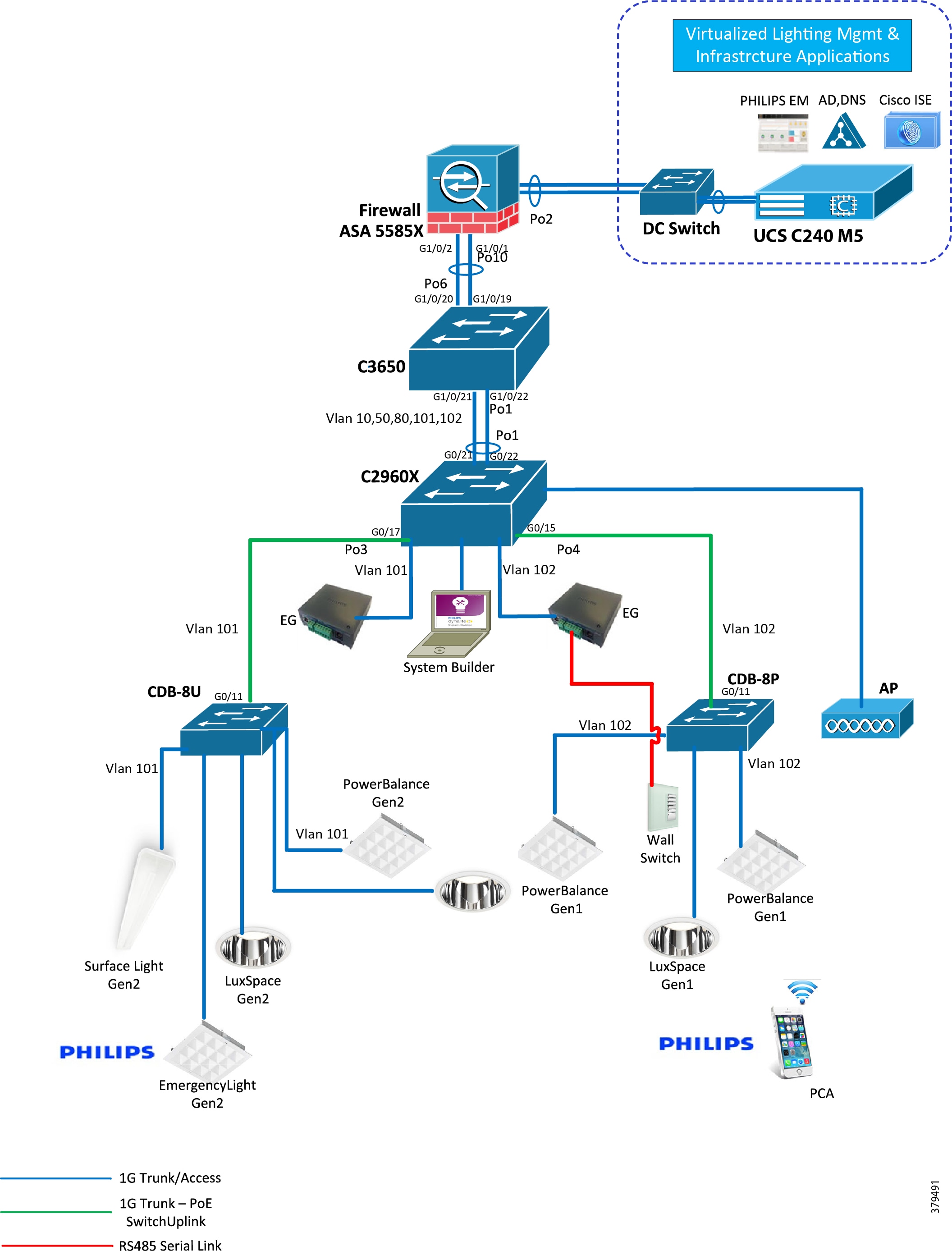
Figure 3 Standalone Signify Lighting Network Star Topology—Logical Topology
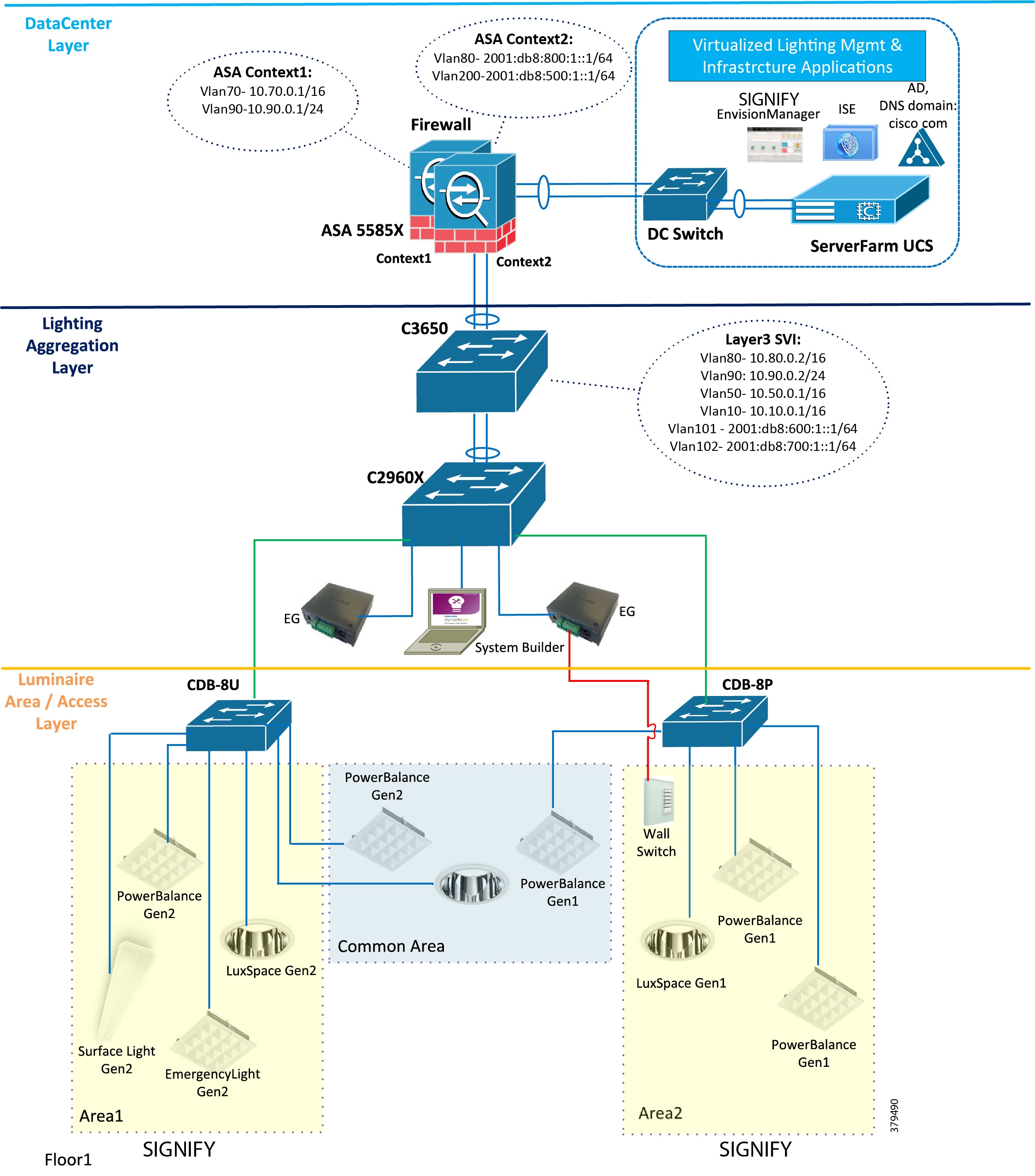
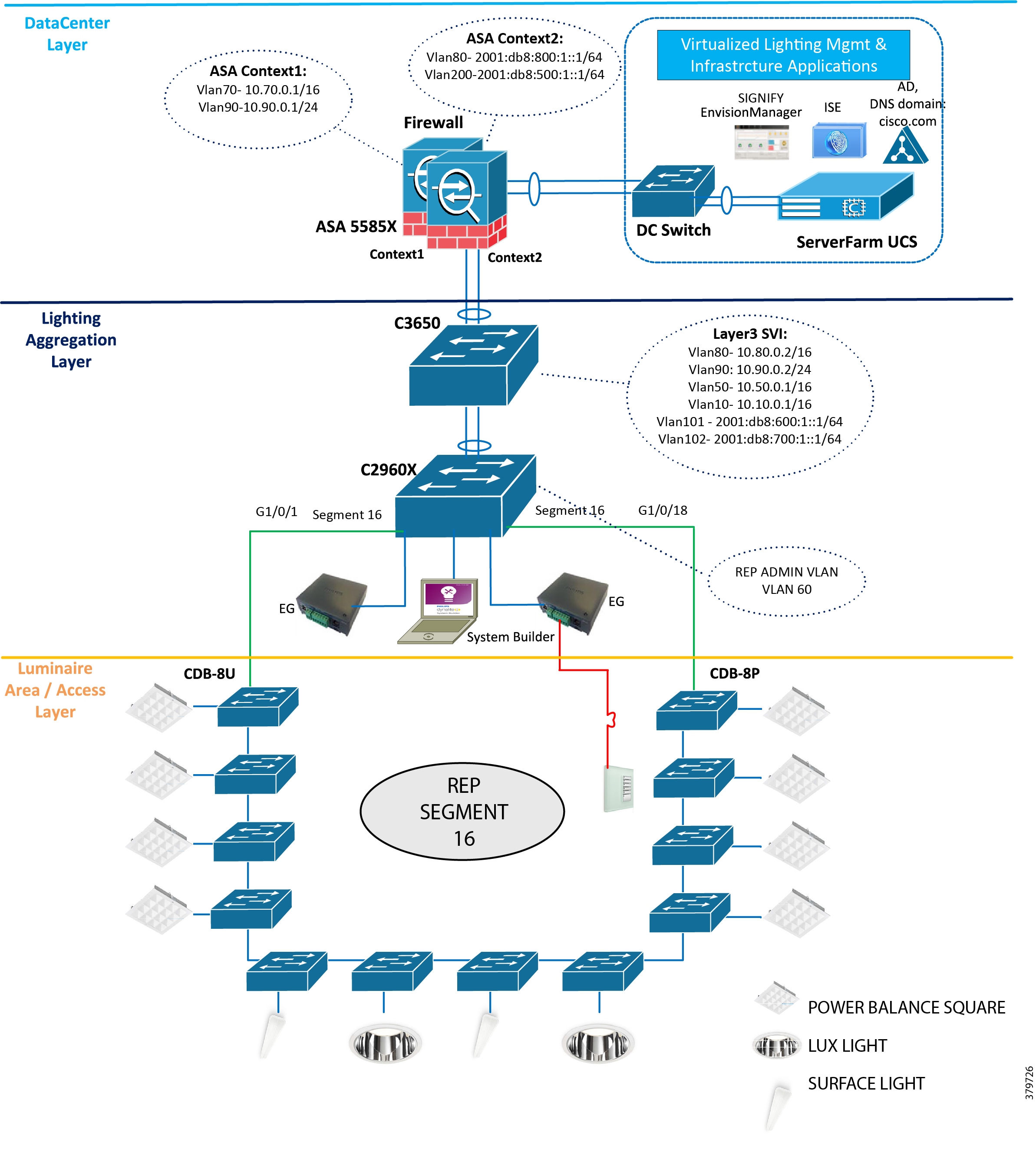
Figure 4 Standalone Signify Lighting Network—Ring Topology
System Components
The components validated within this system consist of a mix of Cisco products (Table 1) and Signify products (Table 2).
CDB-8U model provides up to 480W PoE power, 8 ports to connect to 8 luminaires; each require up to 60W PoE power. |
||
Table 3 provides the list of third party infrastructure components used in the system.
IP Addressing
This section summarizes the VLAN and IPv4 DHCP address pools in the system.
VLANs
Table 4 shows the Layer 2 and Layer 3 VLAN IP addressing of the system.
IPv4 Data Center Network VLAN for Signify Envision Manager Web IT network interface and other servers (ACS, AD/DNS) |
||
Signify Envision Manager Web Lighting Network IPv6 Interface VLAN |
Note: The VLANs and subnet mask shown in Table 4 are only examples that are used in the standalone Cisco Smart+Connected Solutions with Signify Interact Office Wired system deployment validation. VLAN numbering and mask may vary based on your actual deployment; follow best practices as recommended by enterprise IT network engineers.
Dynamic Host Configuration Protocol
Dynamic Host Configuration Protocol (DHCP) for the Signify luminaires IPv6 addressing is not needed since Signify uses Stateless Address Auto Configuration (SLAAC). In SLAAC, a router periodically advertises an IPv6 address prefix. Signify luminaires and Envision Gateway will get the IPv6 address that is built based on that prefix and device MAC address.
The IPv4 DHCP pools are created, as shown in Table 5, on the C3650 for management and wireless clients to enable PCA access to Signify Envision Manager Web.
Note: The DHCP pools and IP range shown in Table 5 are example pools used in the system for validation. Signify Personal Control Application (PCA) will be leveraging corporate IT wireless network. Follow the DHCP pool and IP range creation for appropriate VLANs during the deployment based on Enterprise IT network deployment when integrating a lighting network to an enterprise IT network.
Lighting Aggregation and Network Access
This chapter, which covers the implementation of networking Layer 2, Layer 3, and security features required for a Greenfield standalone lighting network deployment as specified in the Design Guide, includes the following major topics:
■![]() Wiring Closet Access Switch (C2960X)
Wiring Closet Access Switch (C2960X)
■![]() Cisco PoE Switch for Signify Luminaires (CDB)
Cisco PoE Switch for Signify Luminaires (CDB)
Lighting Aggregation Switch
VLAN numbering, IP addressing, and other configurations used in this chapter are the example configurations, as shown in the lighting network topology in Figure 3. However, the VLAN numbering and IP addressing scheme may vary based on network planning in your deployment.
The Catalyst 3650 switch is the lighting network aggregation switch providing IPv6 lighting network router prefix and network Layer 3 routing functionalities for the lighting network. The following sections cover the implementation of Layer 2, Layer 3, and security features as required on the C3650 switch.
Layer 2 and Layer 3 Configuration
This section defines the implementation of VLANs and Layer 3 logical interfaces on the C3650 switch.
1.![]() Configure VLANs, which must be created along with ports assignment on the 3650 switch:
Configure VLANs, which must be created along with ports assignment on the 3650 switch:
2.![]() Create Layer 3 switched virtual interface (SVI) for the VLANs 50, 80, 90, 101, and 102. The configuration below shows SVIs for the VLAN on the C3650 switch:
Create Layer 3 switched virtual interface (SVI) for the VLANs 50, 80, 90, 101, and 102. The configuration below shows SVIs for the VLAN on the C3650 switch:
3.![]() Enable IPv6 unicast routing features on the 3650 switch using the following command:
Enable IPv6 unicast routing features on the 3650 switch using the following command:
Note: Steps 2 and 3 above enable IPv6 routing and router IPv6 prefix advertisements for the IPv6 SLAAC address assignment to Signify Envision gateways and luminaires in a VLAN.
4.![]() Create port channel interfaces on the 3650 to 2960X, the UCS Server, and the Cisco Adaptive Security Appliance (ASA) firewall in the network as shown below:
Create port channel interfaces on the 3650 to 2960X, the UCS Server, and the Cisco Adaptive Security Appliance (ASA) firewall in the network as shown below:
5.![]() Enable EtherChannel on the appropriate physical switch ports connected to the 2960X, UCS server, and ASA. The following configuration shows the port channel assignment to switch physical ports:
Enable EtherChannel on the appropriate physical switch ports connected to the 2960X, UCS server, and ASA. The following configuration shows the port channel assignment to switch physical ports:
Physical Links to 2960X Switch
Physical Links to ASA5585 Firewall Switch
6.![]() Add IPv4 and IPv6 traffic static routes to the ASA with the VLAN80 default gateway as the VLAN80 bridges the lighting and IT network traffic between the ASA and the 3650. The following commands add static routes to the Data Center IPv4 and IPv6 destination networks on the 3650 switch:
Add IPv4 and IPv6 traffic static routes to the ASA with the VLAN80 default gateway as the VLAN80 bridges the lighting and IT network traffic between the ASA and the 3650. The following commands add static routes to the Data Center IPv4 and IPv6 destination networks on the 3650 switch:
7.![]() Enable rapid per-vlan spanning tree:
Enable rapid per-vlan spanning tree:
Security
This section defines the implementation of security features on the C3650 switch.
Disabling Telnet
Since Telnet is not secure, it should be disabled for accessing the device. The following commands disable Telnet and enable only Secure Shell (SSH) access to the 3650 switch.
SNMP Monitoring
Simple Network Management Protocol (SNMP) facilitates the exchange of management information among network devices. System administrators can remotely manage network performance, find and solve network problems, and plan for network growth by using SNMP. The SNMP agent gathers data from the MIB, which is the repository for information about device parameters and network data. The SNMP agent also can send traps (notifications) of certain events, to the SNMP manager.
SNMP v3 is used for monitoring the switches in the lighting network via traps upon switch ports status change and security violations. Enable and configure the SNMP v3 traps on switch to track ports up/down and security violations, as shown below:
Note: The IP address of the network management station (NMS) host is the IP address of the network management tool supporting SNMP v3 that is being used for monitoring the system.
Wiring Closet Access Switch (C2960X)
This section covers wiring closet access switch C2960X Layer 2, Layer 3 networking, and security configurations.
For Star Topology
Layer 2 and Layer 3 Configuration
This section defines the implementation of VLANs and Layer 3 logical interfaces on the C2960X switch.
1.![]() Configure VLANs, which must be created along with ports assignment on the 2960 switch. The following is an example VLAN creation configuration in this system:
Configure VLANs, which must be created along with ports assignment on the 2960 switch. The following is an example VLAN creation configuration in this system:
2.![]() Create Layer 3 SVI for the VLANs as required. The following is an example configuration of SVIs for the VLAN on the C2960 switch.
Create Layer 3 SVI for the VLANs as required. The following is an example configuration of SVIs for the VLAN on the C2960 switch.
3.![]() Create port channel interfaces on the 2960 to 3650 in the network. The following is an example port channel configuration for the network topology shown in Figure 3 above:
Create port channel interfaces on the 2960 to 3650 in the network. The following is an example port channel configuration for the network topology shown in Figure 3 above:
4.![]() Enable EtherChannel on the appropriate physical switch ports connected to the 3650 switch. The following configuration shows the port channel assignment to switch physical ports:
Enable EtherChannel on the appropriate physical switch ports connected to the 3650 switch. The following configuration shows the port channel assignment to switch physical ports:
Physical Links to C3650 Switch
5.![]() Add IPv4 default gateway on the switch as shown below:
Add IPv4 default gateway on the switch as shown below:
6.![]() Configure interfaces on the C2960X switch connected to CDB-1 and CDB-2 PoE switches, as shown below:
Configure interfaces on the C2960X switch connected to CDB-1 and CDB-2 PoE switches, as shown below:
7.![]() Configure interfaces on the C2960X connected to the Envision Gateway in appropriate access VLANs. For example, Envision Gateways shown in the network topology in Figure 3 are in VLAN 101 or VLAN 102 configured, as shown below:
Configure interfaces on the C2960X connected to the Envision Gateway in appropriate access VLANs. For example, Envision Gateways shown in the network topology in Figure 3 are in VLAN 101 or VLAN 102 configured, as shown below:
8.![]() Enable rapid per-vlan spanning tree.
Enable rapid per-vlan spanning tree.
Security
This section defines the implementation for disabling Telnet and enabling SNMP features on the C3650.
Disabling Telnet
Since Telnet is not secure, it should be disabled for accessing the device. The following commands disable Telnet and only enable SSH access to the 3650 switch.
SNMP facilitates the exchange of management information among the network devices. The system administrator can remotely manage the network performance, find and solve network problems, and plan for network growth by using the SNMP. The SNMP agent gathers data from the MIB, which is the repository for information about device parameter and network data. The SNMP agent also sends traps (notifications) of certain events, to the SNMP Manager.
SNMP v3 is used for monitoring the switches in the Lighting network via traps on switch port status change and security violations. Enable and configure SNMP traps on the port to monitor port change status and violations on the device.
Note: The IP address of the NMS host is the address of the network management tool supporting SNMP v3 that is being used for monitoring the system.
Configure and apply the following access-list on the interfaces connecting to the Envision Gateway:
Note: FF12::/16 range is the ipv6 multicast address used by the Signify Envision Gateway for spur connection.
Enable spanning tree BPDU Guard and PortFast on all interfaces connecting to the Envision Gateways.
For Ring Network Topology
Note: This section is optional and required only when the REP ring network topology is implemented in the deployment solutions.
Configurations Required for REP Ring on C2960
This section defines the implementation of VLANs and Layer 2 interfaces on the C2960X switch for the REP Ring Network topology.
Refer to Figure 4 for the topology.
1.![]() Configure VLANs, which must be created along with port assignments on the 2960 switch. The following is an example VLAN creation configuration in this system:
Configure VLANs, which must be created along with port assignments on the 2960 switch. The following is an example VLAN creation configuration in this system:
2.![]() Create the Layer 3 SVI for the VLANs as required. The following is an example configuration of SVIs for the VLAN on the C2960 switch:
Create the Layer 3 SVI for the VLANs as required. The following is an example configuration of SVIs for the VLAN on the C2960 switch:
3.![]() Create REP Admin VLAN on the C2960 switch:
Create REP Admin VLAN on the C2960 switch:
4.![]() Configure interfaces on the C2960X switches edge port connected to the CDB switches in the REP ring:
Configure interfaces on the C2960X switches edge port connected to the CDB switches in the REP ring:
5.![]() Disable spanning tree for VLANs, which are used in the REP network topology:
Disable spanning tree for VLANs, which are used in the REP network topology:
Cisco PoE Switch for Signify Luminaires (CDB)
This section covers the Cisco Catalyst Digital Building PoE switch Layer 2 and security configurations.
Layer 2 and Layer 3 Configuration
This section defines the implementation of VLANs and Layer 3 logical interfaces on the CDB-8U switch.
1.![]() Configure VLANs, which must be created along with ports assignment on the CDB switch:
Configure VLANs, which must be created along with ports assignment on the CDB switch:
2.![]() Create Layer 3 SVI for the VLAN 50 and assign an IP address using DHCP:
Create Layer 3 SVI for the VLAN 50 and assign an IP address using DHCP:
3.![]() Add the IPv4 default gateway on the switch:
Add the IPv4 default gateway on the switch:
4.![]() Configure interfaces on the CDB-8U connected to C2960:
Configure interfaces on the CDB-8U connected to C2960:
5.![]() Configure interfaces on the CDB-8U connected to the Signify luminaires, as shown below in VLAN 101 or 102:
Configure interfaces on the CDB-8U connected to the Signify luminaires, as shown below in VLAN 101 or 102:
The switch CLI command power inline port POE-HA enables Perpetual PoE and Fast PoE features on switch ports. The command power inline port 2-event enables 2-event classification on switch ports for Signify luminaires, to provide power up to 30W.
6.![]() Enable rapid per-vlan spanning tree.
Enable rapid per-vlan spanning tree.
Note: The following steps to enable MAC Authentication Bypass (MAB) are valid only if Cisco ISE is used for MAB-based device authentication MUD_URI visibility in the Cisco Identity Services Engine (ISE). The following steps can be ignored if you do not use ISE in your deployment. However, it is recommended to use ISE for device authentication and profiling for enhanced system network security.
8.![]() Enable MAB in interfaces where PoELC lights are connected:
Enable MAB in interfaces where PoELC lights are connected:
Note: It is recommended to enable MAB in switch ports for luminaires and network security. However, it can be disabled by using "no mab" under the interface configuration.
Note: By default, all the configuration required for Fast PoE, access session, and 2-event classifications are enabled in CDB.
Security
The following sections cover security configurations on the CDB switch for Signify luminaires.
Disabling Telnet
Since it is not secure, Telnet should be disabled for accessing the device:
Spanning Tree Security
Enable spanning tree BPDU Guard and PortFast on all interfaces connecting to the luminaires as shown below:
SNMP Monitoring
Enable and configure the following SNMP v3 traps on switch to track ports up/down and security violations:
Access Lists
Configure and apply the following access list on all the ports connecting to the luminaires:
For Ring Network Topology
Note: This section is optional and required only when REP ring network topology is implemented in the deployment solutions.
Configurations required for REP Ring on CDB
This section defines the implementation of VLANs on the CDB switch for the REP ring network topology.
1.![]() Configure VLANs, which must be created along with ports assignment on the 2960 switch. The following is an example VLAN creation configuration in this system:
Configure VLANs, which must be created along with ports assignment on the 2960 switch. The following is an example VLAN creation configuration in this system:
2.![]() Create Layer 3 SVI for the VLANs as required. The following is an example configuration of SVIs for the VLAN on the C2960 switch:
Create Layer 3 SVI for the VLANs as required. The following is an example configuration of SVIs for the VLAN on the C2960 switch:
3.![]() Create the REP Admin VLAN on the CDB switch:
Create the REP Admin VLAN on the CDB switch:
4.![]() Configure interfaces on the C2960X switch’s edge port connected to CDB switches in the REP ring:
Configure interfaces on the C2960X switch’s edge port connected to CDB switches in the REP ring:
5.![]() Configure VLAN 90 to reach to ISE via ASA:
Configure VLAN 90 to reach to ISE via ASA:
6.![]() Disable spanning tree for VLANs that are used in the REP network topology on CDB switches in the ring topology:
Disable spanning tree for VLANs that are used in the REP network topology on CDB switches in the ring topology:
Note: All the above configurations are required in all the CDB switches participating in the REP ring topology.
Firewall
This chapter, which covers firewall configuration on the ASA in the data center layer for Signify Envision Manager Web security, includes the following major topic:
Firewall (Cisco ASA 5585)
In the Cisco Smart+Connected Solutions with Signify Interact Office Wired solution, ASA acts as a firewall and protects the applications in the data center. Traffic coming into the data center from the network, along with traffic from lighting network, should pass through the ASA firewall.
The ASA is configured to operate as follows:
Several tasks are required to complete ASA configuration. The work flow is shown in Figure 5.
Figure 5 ASA Configuration Flow
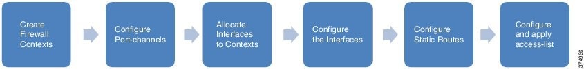
Creating Contexts
Two firewall contexts are created to separate the Lighting Network traffic from the Data Network traffic:
1.![]() Enable mode multi-context on the ASA firewall:
Enable mode multi-context on the ASA firewall:
2.![]() Create a new ASA context for the Lighting Network traffic:
Create a new ASA context for the Lighting Network traffic:
Port Channel to Network
1.![]() ASA is configured with a port channel having two member links to C3650 switch. The port channel includes the two 1 Gig interfaces available on the ASA 5585X. It is configured from the system context and no name or security-level is assigned.
ASA is configured with a port channel having two member links to C3650 switch. The port channel includes the two 1 Gig interfaces available on the ASA 5585X. It is configured from the system context and no name or security-level is assigned.
2.![]() VLAN subinterfaces provide access to different components in the network, such as the data center, management network, and Envision Manager Server. Subinterfaces based on VLANs are configured on the port channel from the system context.
VLAN subinterfaces provide access to different components in the network, such as the data center, management network, and Envision Manager Server. Subinterfaces based on VLANs are configured on the port channel from the system context.
The VLAN and subinterface configuration for server network access:
VLAN and subinterface configuration for data center access on the firewall:
VLAN and subinterface configuration for data network access on the firewall:
VLAN and subinterface configuration for the lighting network on the firewall:
Allocating Interfaces to Firewall Contexts
The port channel subinterfaces created in the previous section are assigned to the firewall contexts, as shown below. This segregates the lighting network traffic from the data network traffic into different security contexts on the firewall.
Interface Configuration
Within each of the security contexts, the interfaces are configured with names, security levels, and IP addresses. Table 6 summarizes the interface configuration used along with the zones each interface is part of in the contexts.
The firewall security level can be configured between 0 and 100; 0 is the least secure zone and 100 is the most secure zone. See Table 7.
Note: On port channel 10.80 in ASA, we enable router advertisement suppression.
Static Routes
The following static routes are configured on the ASA contexts:
Access Control Lists and Access Control List Entries
By default, ASA denies all traffic moving from a lower security level to a higher security level. Access control lists (ACLs) are configured to enable required traffic between interfaces. The access list entries (ACEs) follow.
ACE to allow traffic from the Envision Gateway to the Envision Manager in Lighting Management context:
Apply the access-list on the lighting network interface:
ISE enabling HTTP and HTTPS access to Envision Manager in admin context:
ACE allowing management network reachability to ISE in the Data Center through admin context:
Apply the access-list on the data network interface:
UCS and Virtualization
This chapter includes the following major topics:
■![]() UCS and Virtualization Infrastructure
UCS and Virtualization Infrastructure
■![]() VM Installation (ISE, Signify Envision Manager Web)
VM Installation (ISE, Signify Envision Manager Web)
Note: The Cisco Unified Computing System (UCS) C-Series server platform discussed in this chapter is used in the deployment of all data center applications (for example, Signify Envision Manager and applications like Cisco ISE) through server virtualization. However, any UCS server series or desktop server can be chosen for deployment based on the application's hardware requirements matching the server hardware resources.
UCS and Virtualization Infrastructure
This section describes how to deploy a Cisco UCS C220 M5 server to provide the virtualized infrastructure required to deploy virtual machines (VMs), for example, the Signify Envision Manager Web, ISE, and CA server. Where applicable, refer to the following Cisco and VMware documentation for details:
■![]() Cisco UCS C220 M5 Rack Server Installation Guide:
Cisco UCS C220 M5 Rack Server Installation Guide:
–![]() https://www.cisco.com/c/en/us/td/docs/unified_computing/ucs/c/hw/C220M5/install/C220M5/C220M5_chapter_01.html
https://www.cisco.com/c/en/us/td/docs/unified_computing/ucs/c/hw/C220M5/install/C220M5/C220M5_chapter_01.html
■![]() Cisco UCS C-Series Servers Integrated Management Controller GUI Configuration Guide, Release 4.0:
Cisco UCS C-Series Servers Integrated Management Controller GUI Configuration Guide, Release 4.0:
–![]() https://www.cisco.com/c/en/us/td/docs/unified_computing/ucs/c/sw/cli/config/guide/4_0/b_Cisco_UCS_C-Series_CLI_Configuration_Guide_40.html
https://www.cisco.com/c/en/us/td/docs/unified_computing/ucs/c/sw/cli/config/guide/4_0/b_Cisco_UCS_C-Series_CLI_Configuration_Guide_40.html
■![]() vSphere Installation and Setup:
vSphere Installation and Setup:
–![]() https://docs.vmware.com/en/VMware-vSphere/6.0/com.vmware.vsphere.install.doc/GUID-7C9A1E23-7FCD-4295-9CB1-C932F2423C63.html
https://docs.vmware.com/en/VMware-vSphere/6.0/com.vmware.vsphere.install.doc/GUID-7C9A1E23-7FCD-4295-9CB1-C932F2423C63.html
Figure 6 shows the virtualization configuration flow.
Figure 6 Flow Diagram for Virtualization Configuration
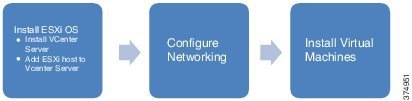
ESXi Installation and Configuration
To install and configure ESXi on a UCS C220 server, refer to the Installing & Setting Up ESXi sections in the vSphere Installation and Setup Guide.
Refer to the detailed vCenter server installation steps in the "Installing vCenter server" section of the vSphere Installation and Setup Guide at the following URL:
■![]() https://docs.vmware.com/en/VMware-vSphere/6.0/com.vmware.vsphere.install.doc/GUID-7C9A1E23-7FCD-4295-9CB1-C932F2423C63.html
https://docs.vmware.com/en/VMware-vSphere/6.0/com.vmware.vsphere.install.doc/GUID-7C9A1E23-7FCD-4295-9CB1-C932F2423C63.html
Note: We recommend immediately completing all licensing through the vCenter management application during the ESXi installation process.
ESXi Networking
This section covers the ESXi networking configuration for UCS C-Series server platform for the data center applications like Signify Envision Manager, and Cisco ISE as shown in Figure 6 above.
Note: The VMware vSwitch configurations for the UCS platform discussed in this section are example networking configurations for the Signify Envision Manager Web and other applications deployment for the topology shown in Figure 6. The data center networking switches and configurations may vary based on the Enterprise IT network data center deployment. Where applicable, follow the deployment procedures used for the enterprise data center deployment.
Refer to the following Vmware vSphere networking configuration to configure virtual machines ESXi networking on the UCS ESXi host:
■![]() https://docs.vmware.com/en/VMware-vSphere/6.0/com.vmware.vsphere.install.doc/GUID-7C9A1E23-7FCD-4295-9CB1-C932F2423C63.html
https://docs.vmware.com/en/VMware-vSphere/6.0/com.vmware.vsphere.install.doc/GUID-7C9A1E23-7FCD-4295-9CB1-C932F2423C63.html
Note: Make sure to create two port groups for Signify Envision Manager Web application VML: one for the IPv4 network (example: DC_Vlan70) and the other for the Lighting IPv6 network.
VM Installation (ISE, Signify Envision Manager Web)
The following sections describe procedures involved in deploying the virtual machines for ACS and a Window Server 2012 server for AD/DNS services.
Configuring Network Device Authentication (ISE) (Optional)
This section covers how to deploy Cisco ISE 2.0 on the UCS server platform in the data center for network devices authentication (RADIUS) and security.
Installation of Cisco Identity Services Engine
The prerequisites and the necessary information to install ISE can be found at the following URL:
■![]() https://www.cisco.com/c/en/us/td/docs/security/ise/2-4/install_guide/b_ise_InstallationGuide24/b_ise_InstallationGuide24_chapter_00.html
https://www.cisco.com/c/en/us/td/docs/security/ise/2-4/install_guide/b_ise_InstallationGuide24/b_ise_InstallationGuide24_chapter_00.html
This document describes different deployment scenarios with ISE. One should choose deployment scenario according to the use case needs.
Configuring Cisco Identity Services Engine
ISE 2.0 is used for providing device authentication and authorization in the network via RADIUS. ISE is deployed in a VM and assigned an IP address in the VLAN 70 residing behind the firewall. The firewall ports need to be opened for RADIUS communication from the VLAN 90 to ISE.
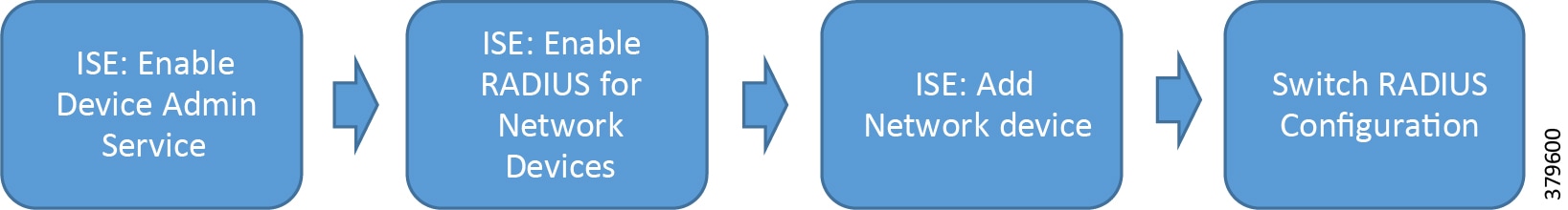
Figure 7 AAA Configuration Flow
Note: The deployment of ISE in the solution is optional for the MUD-URI feature. However, it is recommended to use ISE for devices authentication and enhanced network security.
The following configurations are required to implement MUD-URI visibility in ISE.
Perform the following steps on each switch in the network (for example, Cisco Catalyst 3650 and Cisco CDB and Cisco Catalyst 3650 switches in the deployment, as shown in Figure 3) to configure AAA.
1.![]() On the switches, configure ISE as the RADIUS server:
On the switches, configure ISE as the RADIUS server:
ISE is the name of the RADIUS defined. Any user-defined name can be used. The RADIUS server "ISE" defined is added to the AAA group-server.
2.![]() Create a local user with full privilege for fall back with the username command as shown here:
Create a local user with full privilege for fall back with the username command as shown here:
3.![]() Configure login authentication and exec and console authorization using the following commands, which show the different authentication groups that could be created.
Configure login authentication and exec and console authorization using the following commands, which show the different authentication groups that could be created.
4.![]() Use the Telnet Console method on Virtual Teletype (VTY) authentication and authorization:
Use the Telnet Console method on Virtual Teletype (VTY) authentication and authorization:
With this step, the different authentication groups that have been created should be attached to the respective login type.
ISE Configuration
Perform the following steps on the ISE server for enabling RADIUS-based device authentication and authorization:
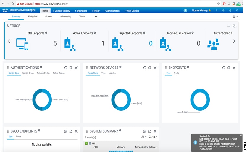
1.![]() Log in to ISE. Figure 8 shows ISE summary after successful login.
Log in to ISE. Figure 8 shows ISE summary after successful login.
Figure 8 ISE Login Success Page
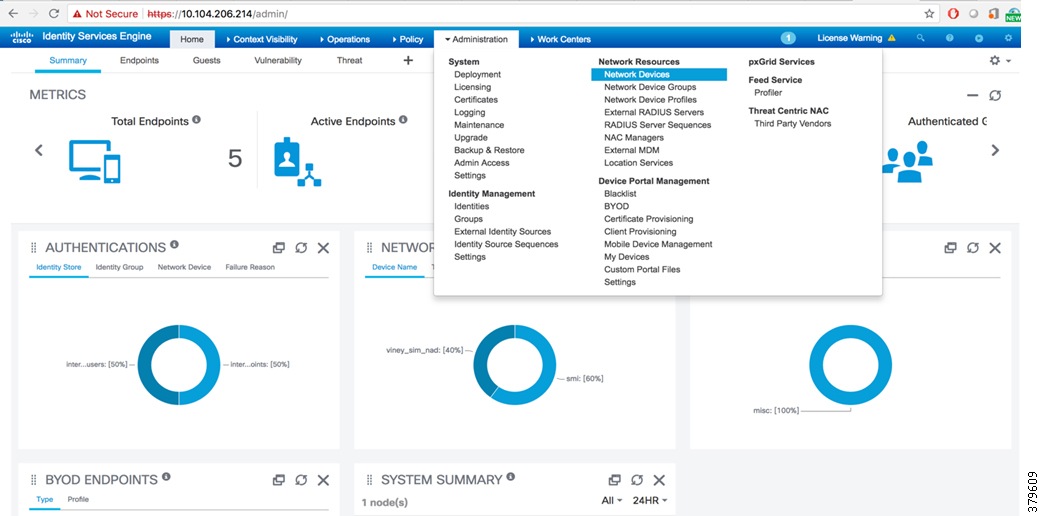
2.![]() Add the 3850 standalone switch or the stack as a network device to ISE. To add Network Device, select Network Devices from Administration > Network Resources, as shown in Figure 9.
Add the 3850 standalone switch or the stack as a network device to ISE. To add Network Device, select Network Devices from Administration > Network Resources, as shown in Figure 9.
Figure 9 Select Network Devices in ISE
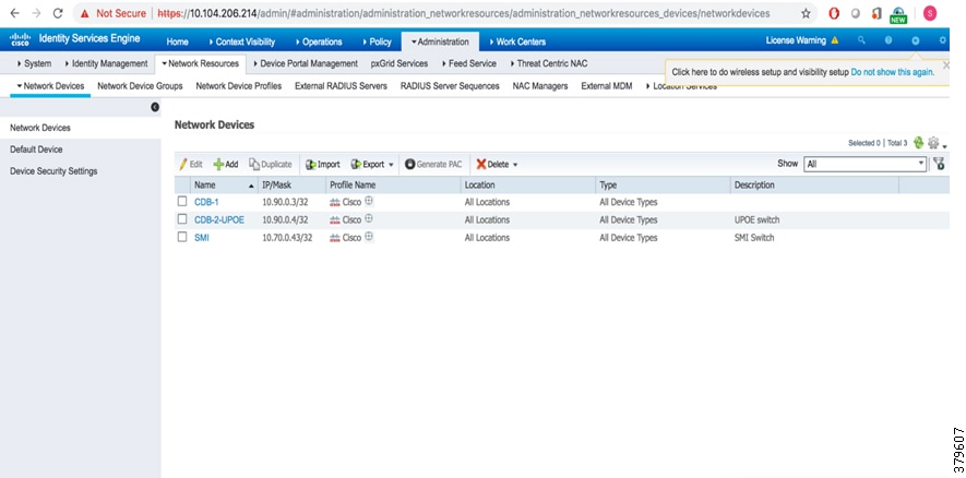
3.![]() On selecting Network Devices, the page should display devices (if any) that were added, as shown in Figure 10.
On selecting Network Devices, the page should display devices (if any) that were added, as shown in Figure 10.
Figure 10 Network Devices in ISE
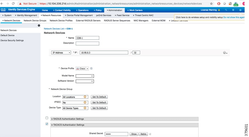
4.![]() To add network device to the list, click Add, enter the device name and the correct IP address. The IP address of the network device should be reachable from ISE. See Figure 11.
To add network device to the list, click Add, enter the device name and the correct IP address. The IP address of the network device should be reachable from ISE. See Figure 11.
Figure 11 Adding a Network Device in ISE
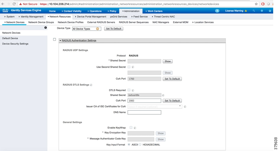
5.![]() After adding a network device, select the RADIUS authentication settings and then enter the pre-shared key that is common to the network device, as shown in Figure 12. This pre-shared key should be same as the key added in the AAA configuration of the network device.
After adding a network device, select the RADIUS authentication settings and then enter the pre-shared key that is common to the network device, as shown in Figure 12. This pre-shared key should be same as the key added in the AAA configuration of the network device.
Figure 12 RADIUS Authentication Settings
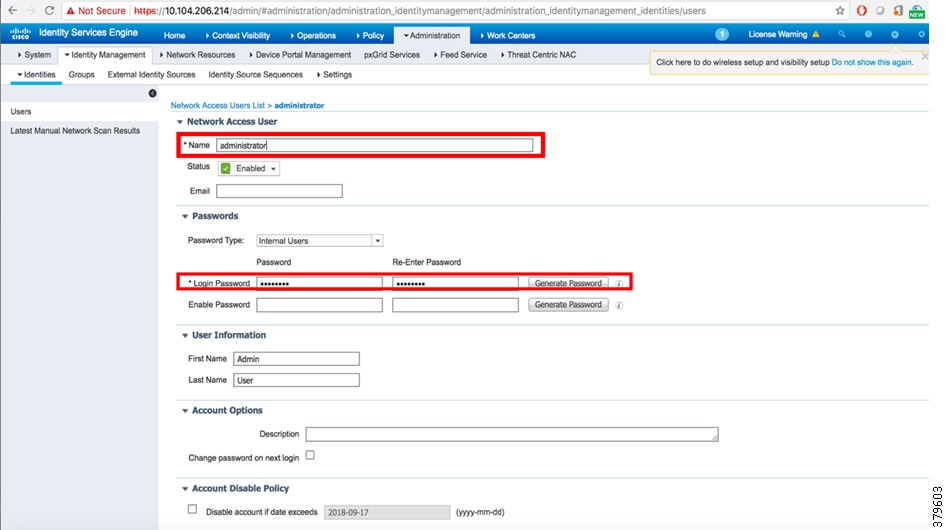
6.![]() To create an identity (user), go to Administration > Identity Management > Identities > Users. Add the Name and the login password, as shown in Figure 13 and Figure 14. These credentials will be used to log in to the network device from ISE.
To create an identity (user), go to Administration > Identity Management > Identities > Users. Add the Name and the login password, as shown in Figure 13 and Figure 14. These credentials will be used to log in to the network device from ISE.
Figure 13 Adding a User Identity in Identity Management
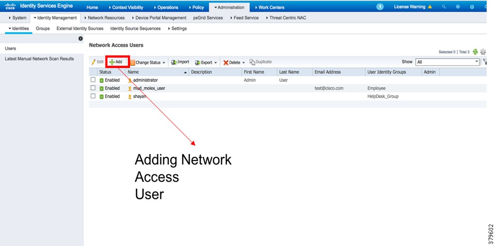
Figure 14 Creating a New User in Identity Management
This completes the ISE RADIUS configuration for network devices authentication and authorization.
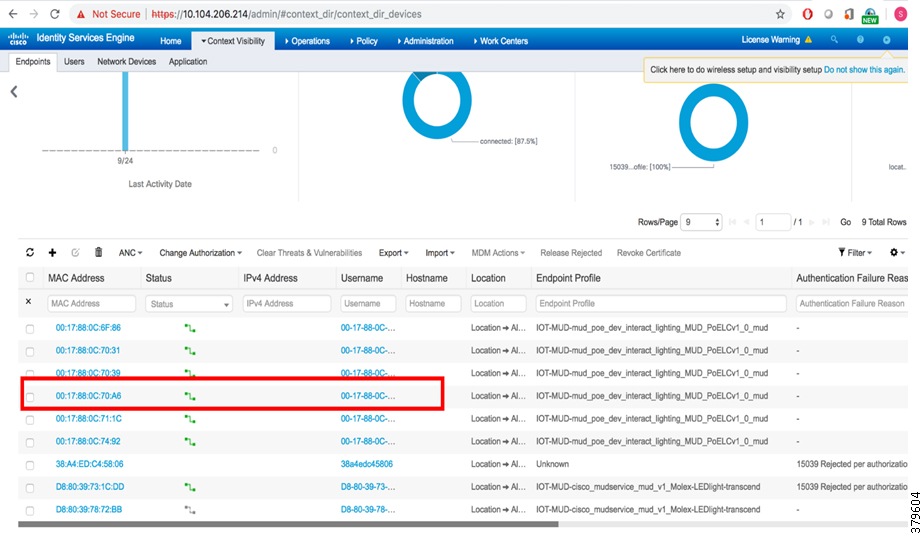
7.![]() After performing the above steps, the endpoints can be seen at Context Visibility > Endpoints (Figure 15).
After performing the above steps, the endpoints can be seen at Context Visibility > Endpoints (Figure 15).
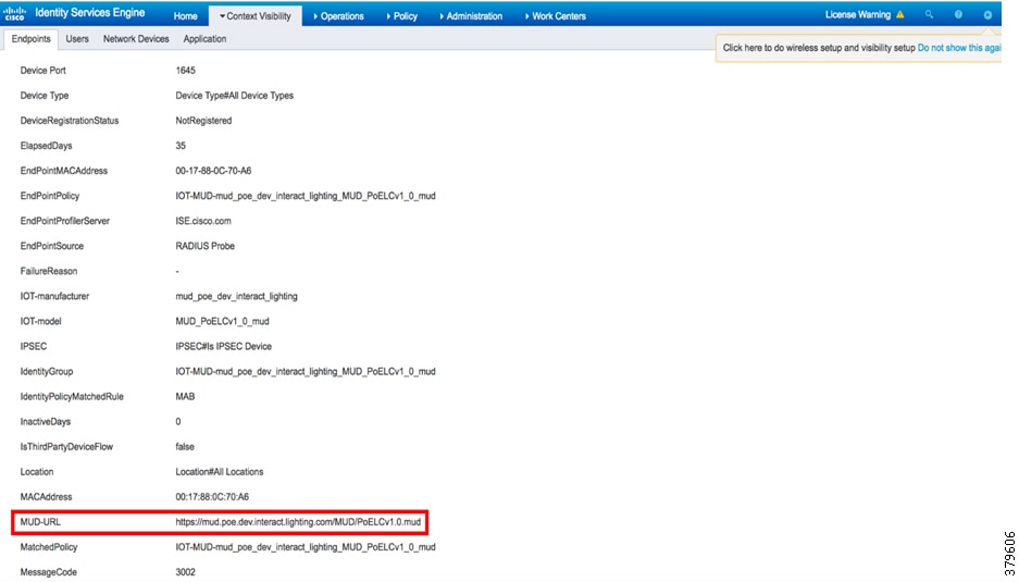
8.![]() On clicking one of the endpoints, scroll to the bottom of the Attributes tab and see the mud-uri. This is shown in Figure 16.
On clicking one of the endpoints, scroll to the bottom of the Attributes tab and see the mud-uri. This is shown in Figure 16.
Signify Envision Manager Web
This section covers high-level installation steps for Signify Envision Manager on a VM on the UCS Server.
Note: The steps covered in this section are a high-level sequence of steps to install Signify Envision Manager Web. The Signify EnvisionManagerWeb_Rel1-5-1_InstallationGuide_20180830_V3Fin, which is supplied by Signify, must be used for detailed steps for Envision Manager Web installation. Refer to this guide for these steps.
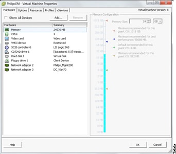
1.![]() Create a VM with the hardware and software requirements and configure two network adapters, as shown in Figure 17:
Create a VM with the hardware and software requirements and configure two network adapters, as shown in Figure 17:
Figure 17 Network Adapter Configuration for the Envision Manager VM
2.![]() Install the Envision Manager Web prerequisites.
Install the Envision Manager Web prerequisites.
Note: Make sure no other applications are running on the same machine using any port that is Signify referenced in Chapter 1.5.2 of the above mentioned installation guide. It is observed that if any other application server (for example, IIS) is running on the same Envision Manager machine with port clash (for example, port 80), the Envision Manager services do not start properly.
4.![]() Launch the Envision Manager.
Launch the Envision Manager.
Figure 18 shows the Envision Manager Web UI after the Envision Manager installation using the URL: https://<FQDN of EM>/em/login.
Figure 18 Envision Manager Web User Interface
Note: It is not recommended as mandatory to upload a trusted Certificate Authority (CA) provided SSL certificate for the Envision Manager server for securely accessing the Envision Manager server using HTTPS. Make sure the SSL certificate is obtained as per the certificate requirements provided by Signify.
This completes the Signify Envision Manager Web installation.
Signify Lighting Use Cases
This chapter, which covers high-level steps for Signify lighting use cases, includes the following major topics:
■![]() Luminaire Control and Management
Luminaire Control and Management
Note: The detailed implementation steps for commissioning, control, and management of lighting use cases described in this chapter are beyond the scope of this document and should be implemented by Signify system experts with relevant Signify documents.
Commissioning of Luminaires
This section describes high-level summary of steps to be followed for commissioning of Signify luminaires. Where applicable, the steps described in this section should be implemented using the Connected Lighting PoE Commissioning Guide supplied by the Signify Commissioning/support engineer.
Refer to the Connected Lighting PoE Commissioning Guide for the detailed step-by-step procedure for commissioning Signify Luminaries and Area Controllers (Envision Gateways).
Luminaire Control and Management
This section covers the high-level implementation steps for lighting control and management use cases using Signify Envision Manager, Personal Control Application (PCA), and the wall switch.
The steps described in this section provide a high-level summary of steps for implementing a lighting control and management for areas as prepared in the job file during on-site commissioning.
Refer to the Signify wEnvisionSuite Installation Guide v1.1 and wEnvisionManager User Guide v1.1 for detailed steps for implementation.
Envision Manager Web
Signify Envision Manager Web has a simple graphical interface, which makes it easy for building and facility managers to control the entire lighting system and to perform complex functions.
1.![]() Get a copy of the System Builder job file, which was prepared during commissioning, in the Signify Envision Manager server machine.
Get a copy of the System Builder job file, which was prepared during commissioning, in the Signify Envision Manager server machine.
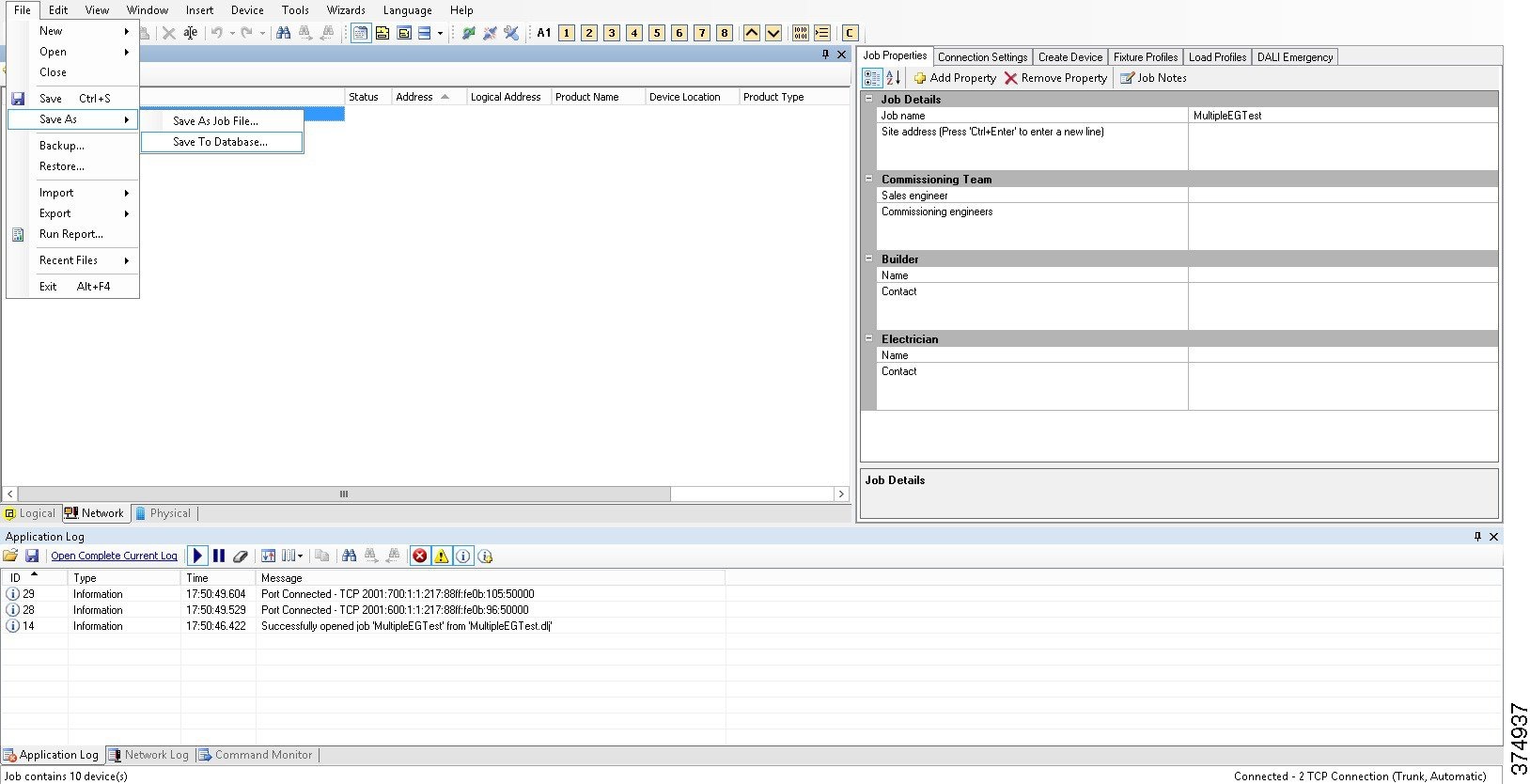
2.![]() Open the saved Job File in using System Builder application on the Envision Manager server and save it to the database, as shown in Figure 19.
Open the saved Job File in using System Builder application on the Envision Manager server and save it to the database, as shown in Figure 19.
Figure 19 Saving Job File to Database
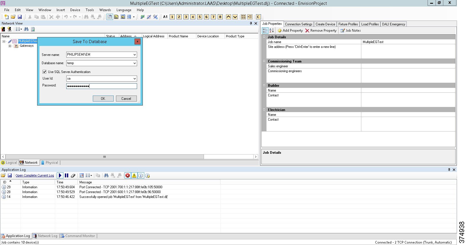
3.![]() Enter the appropriate database credentials, as shown in Figure 20.
Enter the appropriate database credentials, as shown in Figure 20.
Figure 20 SQL Authentication for Saving Job File to Database
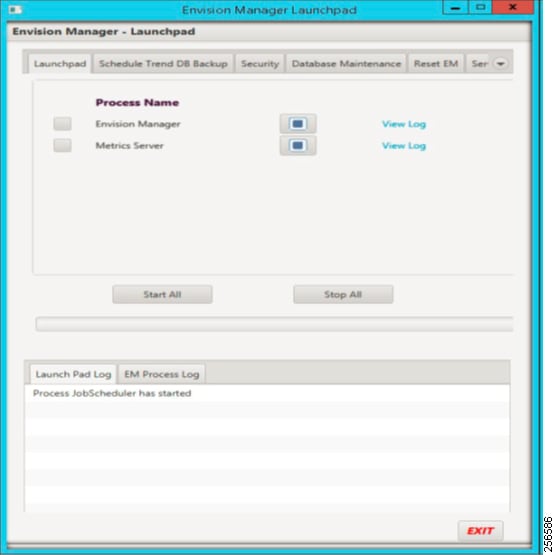
4.![]() Launch the Envision Suite and start all the services, as shown in Figure 21.
Launch the Envision Suite and start all the services, as shown in Figure 21.
Figure 21 Launching Envision Manager
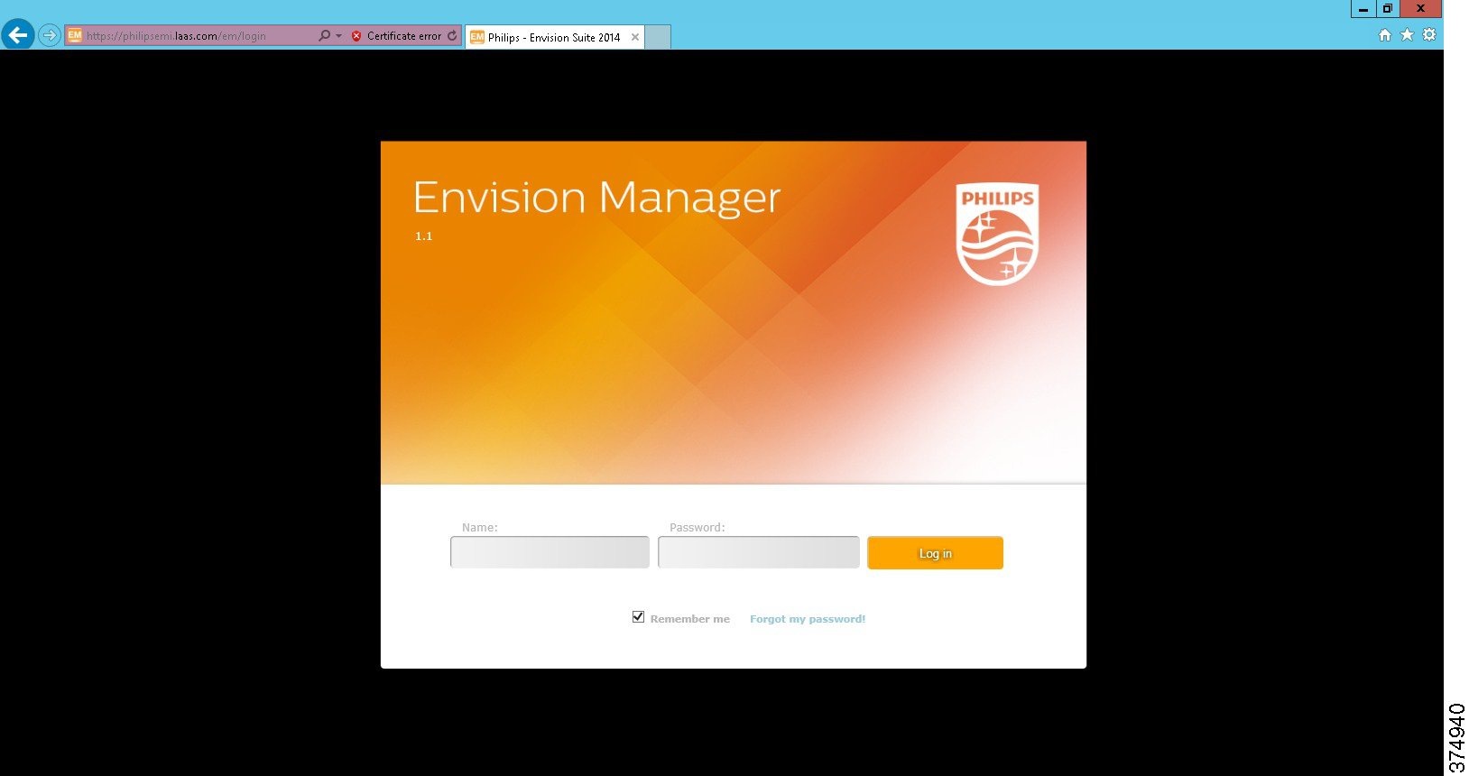
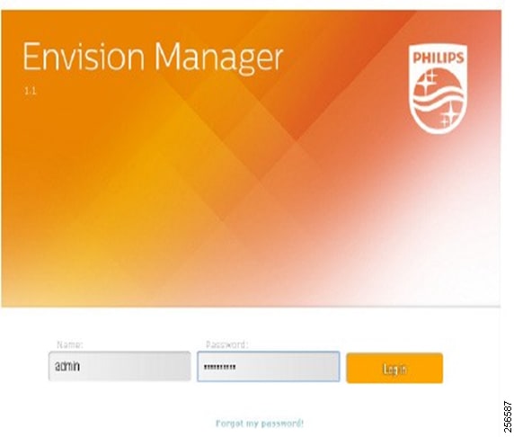
5.![]() After the services restart, open the Google Chrome browser on Envision Manager web and then log on to the Envision Manager Web UI using the appropriate user's login credentials, as shown in Figure 22.
After the services restart, open the Google Chrome browser on Envision Manager web and then log on to the Envision Manager Web UI using the appropriate user's login credentials, as shown in Figure 22.
Figure 22 User Authentication for EM
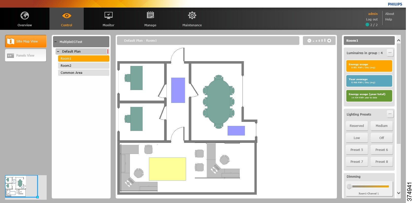
6.![]() Luminaire’s control operations on Envision Manager can be performed as required by navigating to the Control tab and selecting the appropriate area and control action, as shown in Figure 23.
Luminaire’s control operations on Envision Manager can be performed as required by navigating to the Control tab and selecting the appropriate area and control action, as shown in Figure 23.
Figure 23 Controlling Luminaires in an Area using the Various Presets
Personal Control Application
This section covers Signify Personal Control Application (PCA) provisioning for luminaire control in an area.
Prerequisites
■![]() You have the Apple iPhone or Android devices with the appropriate version of iOS and Android version as per Signify PCA requirements.
You have the Apple iPhone or Android devices with the appropriate version of iOS and Android version as per Signify PCA requirements.
■![]() Based on the Signify EnvisionManagerWeb_Rel1-5-1_InstallationGuide_20180830_V3Fin.pdf certificate requirements, you should have a valid SSL certificate issued by an official CA for Envision Manager server to which PCA is establishing a secure (HTTPS) connection. The certificate request should match the certificate requirements as specified by Signify.
Based on the Signify EnvisionManagerWeb_Rel1-5-1_InstallationGuide_20180830_V3Fin.pdf certificate requirements, you should have a valid SSL certificate issued by an official CA for Envision Manager server to which PCA is establishing a secure (HTTPS) connection. The certificate request should match the certificate requirements as specified by Signify.
Note: It is observed that THE SSL certificate issued for the Envision Manager should be a trusted root certificate for the corresponding iOS. For example, the list of trusted root certificates for iOS8 can be found at the following link:
–![]() https://support.apple.com/en-us/HT204132
https://support.apple.com/en-us/HT204132
■![]() You have uploaded the SSL certificate on the Envision Manager server by following the Signify EnvisionManagerWeb_Rel1-5-1_InstallationGuide_20180830_V3Fin.pdf.
You have uploaded the SSL certificate on the Envision Manager server by following the Signify EnvisionManagerWeb_Rel1-5-1_InstallationGuide_20180830_V3Fin.pdf.
Installation and Configuration
1.![]() Install PCA by following the procedure as mentioned by the Apple Store or Android Play Store.
Install PCA by following the procedure as mentioned by the Apple Store or Android Play Store.
2.![]() Steps for configuration and usage for PCA are available in the following Signify PCA user guides:
Steps for configuration and usage for PCA are available in the following Signify PCA user guides:
–![]() ConnectedOffice_PCA_IOS_UG_20160902_V3Fin.pdf or for Android
ConnectedOffice_PCA_IOS_UG_20160902_V3Fin.pdf or for Android
Related Documentation
This appendix lists Cisco and Signify documentation referred to in this document.
Cisco Documentation
■![]() Cisco Smart+Connected Solutions with Signify Interact Office Wired: A Design Guide:
Cisco Smart+Connected Solutions with Signify Interact Office Wired: A Design Guide:
–![]() https://docs.cisco.com/share/s/dID5vdxjTISQV1VrkB6a9Q
https://docs.cisco.com/share/s/dID5vdxjTISQV1VrkB6a9Q
■![]() Cisco UCS C220M5 Installation:
Cisco UCS C220M5 Installation:
–![]() https://www.cisco.com/c/en/us/td/docs/unified_computing/ucs/c/hw/C220M5/install/C220M5/C220M5_chapter_01.html
https://www.cisco.com/c/en/us/td/docs/unified_computing/ucs/c/hw/C220M5/install/C220M5/C220M5_chapter_01.html
■![]() Installation and Upgrade Guide for Cisco Identity Service Engine:
Installation and Upgrade Guide for Cisco Identity Service Engine:
–![]() https://www.cisco.com/c/en/us/td/docs/security/ise/2-3/install_guide/b_ise_InstallationGuide23/b_ise_InstallationGuide23_chapter_010.html
https://www.cisco.com/c/en/us/td/docs/security/ise/2-3/install_guide/b_ise_InstallationGuide23/b_ise_InstallationGuide23_chapter_010.html
■![]() Autonomous AP and Bridge Basic Configuration Template (Cisco Support Community):
Autonomous AP and Bridge Basic Configuration Template (Cisco Support Community):
–![]() https://supportforums.cisco.com/document/61936/autonomous-ap-and-bridge-basic-configuratio n-template
https://supportforums.cisco.com/document/61936/autonomous-ap-and-bridge-basic-configuratio n-template
–![]() http://www.cisco.com/c/en/us/td/docs/ios/12_2/configfun/configuration/guide/ffun_c/fcf014.html
http://www.cisco.com/c/en/us/td/docs/ios/12_2/configfun/configuration/guide/ffun_c/fcf014.html
Signify Documentation
Table 8 provides the list of Signify documentation.
EnvisionManagerWeb_Rel1-5-1_InstallationGuide_20180830_V3Fin.pdf |
|||
Glossary
Table 9 lists acronyms and initialisms used in this document.
 Feedback