- Preface
- Chapter 1: CPwE IDMZ Overview
- Chapter 2: System Design Considerations
- Chapter 3: Configuring the Infrastructure
- Chapter 4: CPwE IDMZ Troubleshooting
- Appendix A: References
- Appendix B: Test Hardware and Software
- Appendix C: Acronyms and Initialisms
- Appendix D: About the Cisco Validated Design (CVD) Program
- Configuring IDMZ Network Infrastructure
- Configuring Network Services
Configuring the Infrastructure
This chapter describes how to configure IDMZ infrastructure in the CPwE architecture based on the design considerations of the previous chapters. It covers the configuration of the network infrastructure, network services, data transfer, remote access services and network and application security, all from an IDMZ perspective. The included configurations have been validated during the testing effort.
Configuring IDMZ Network Infrastructure
This section describes validated configurations for the network infrastructure that establishes the IDMZ within the CPwE architecture, such as firewalls and switches.
Industrial Zone Firewall Configuration
The following firewall configuration steps are covered in this section:
Active/Standby Firewall Configuration

Note This guide assumes that the user has already performed the initial setup and hardening of the Cisco Firepower 2100. For more details on these configurations, refer to:
The following steps describe the initial configuration of the active and standby IDMZ firewalls:
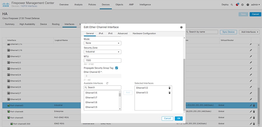
Step 1![]() Configure interfaces for the Industrial and Enterprise Zones (see Figure 3-1):
Configure interfaces for the Industrial and Enterprise Zones (see Figure 3-1):
a.![]() In Cisco FMC, select Devices > Device Management and click Edit for your FTD device. The Interfaces page is selected by default.
In Cisco FMC, select Devices > Device Management and click Edit for your FTD device. The Interfaces page is selected by default.
b.![]() Click Add Interfaces > Ether Channel Interface.
Click Add Interfaces > Ether Channel Interface.
c.![]() On the General tab, set the Ether Channel ID to a number between 1 and 48.
On the General tab, set the Ether Channel ID to a number between 1 and 48.
d.![]() In the Available Interfaces area, click an interface and then click Add to move it to the Selected Interfaces area. Repeat for all interfaces you want to make members.
In the Available Interfaces area, click an interface and then click Add to move it to the Selected Interfaces area. Repeat for all interfaces you want to make members.
Note![]() Make sure all interfaces are the same type and speed. The first interface you add determines the type and speed of the EtherChannel. Any non-matching interfaces you add will be put into a suspended state. The FMC does not prevent you from adding non-matching interfaces.
Make sure all interfaces are the same type and speed. The first interface you add determines the type and speed of the EtherChannel. Any non-matching interfaces you add will be put into a suspended state. The FMC does not prevent you from adding non-matching interfaces.
f.![]() Click Save. Make sure to Deploy changes when configuration is complete.
Click Save. Make sure to Deploy changes when configuration is complete.
Figure 3-1 FMC EtherChannel Interface Configuration
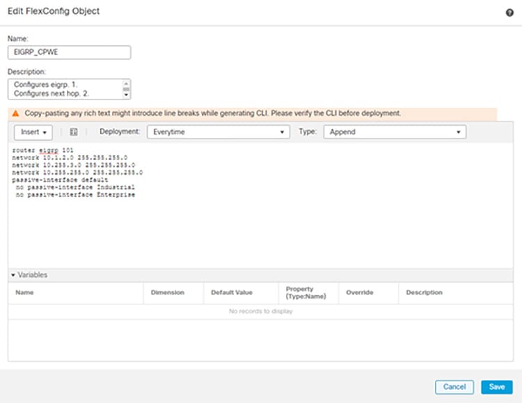
Step 2![]() Configure EIGRP as the dynamic routing protocol (see Figure 3-2):
Configure EIGRP as the dynamic routing protocol (see Figure 3-2):
Note![]() FlexConfig is used to allow you to implement features that are not yet directly supported through FMC policies and settings. FlexConfig can be a useful tool when migrating from ASA to FTD and there are compatible features you are using (and continuing to use) that FMC does not directly support.
FlexConfig is used to allow you to implement features that are not yet directly supported through FMC policies and settings. FlexConfig can be a useful tool when migrating from ASA to FTD and there are compatible features you are using (and continuing to use) that FMC does not directly support.
a.![]() In FMC, select Objects > Object Management and navigate to FlexConfig > FlexConfig Objec t.
In FMC, select Objects > Object Management and navigate to FlexConfig > FlexConfig Objec t.
b.![]() Click Add FlexConfig Object.
Click Add FlexConfig Object.
c.![]() Give a meaningful name to the object, and insert the desired EIGRP configuration for the FTD (see Figure 3-2 for an example).
Give a meaningful name to the object, and insert the desired EIGRP configuration for the FTD (see Figure 3-2 for an example).
Figure 3-2 FMC EIGRP FlexConfig Object
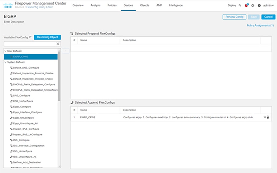
d.![]() Continuing in FMC, select Devices > FlexConfig and click New Policy.
Continuing in FMC, select Devices > FlexConfig and click New Policy.
e.![]() Give a meaningful name to the policy and in the Available Devices area, click an interface and then click Add to Policy to move it to the Selected Devices area. Repeat for all devices you want to make this policy to apply.
Give a meaningful name to the policy and in the Available Devices area, click an interface and then click Add to Policy to move it to the Selected Devices area. Repeat for all devices you want to make this policy to apply.
g.![]() In the Available FlexConfig tab, under User Defined, select the FlexConfig object for EIGRP and click > to move it to the Selected Append FlexConfigs area.
In the Available FlexConfig tab, under User Defined, select the FlexConfig object for EIGRP and click > to move it to the Selected Append FlexConfigs area.
h.![]() Click Save and Deploy changes to the FTD.
Click Save and Deploy changes to the FTD.
Figure 3-3 FMC EIGRP Configuration with FlexConnect
Step 3![]() Configure active/standby failover mode on each firewall and the failover link between the two (see Figure 3-4):
Configure active/standby failover mode on each firewall and the failover link between the two (see Figure 3-4):
a.![]() In FMC, navigate to Devices > Device Management.
In FMC, navigate to Devices > Device Management.
b.![]() From the Add drop-down menu, choose High Availability.
From the Add drop-down menu, choose High Availability.
c.![]() Enter a display Name for the high availability pair.
Enter a display Name for the high availability pair.
d.![]() Under Device Type, choose Firepower Threat Defense.
Under Device Type, choose Firepower Threat Defense.
e.![]() Choose the Primary Peer device for the high availability pair.
Choose the Primary Peer device for the high availability pair.
f.![]() Choose the Secondary Peer device for the high availability pair.
Choose the Secondary Peer device for the high availability pair.
h.![]() Under High Availability Link, choose an Interface with enough bandwidth to reserve for failover communications.
Under High Availability Link, choose an Interface with enough bandwidth to reserve for failover communications.
Note![]() Only interfaces that do not have a logical name and do not belong to a security zone,will be listed in the Interface drop-down menu in the Add High Availability Pair dialog.
Only interfaces that do not have a logical name and do not belong to a security zone,will be listed in the Interface drop-down menu in the Add High Availability Pair dialog.
i.![]() Type any identifying Logical Name.
Type any identifying Logical Name.
j.![]() Type a Primary IP address for the failover link on the active unit. This address should be on an unused subnet. This subnet can be 31-bits (255.255.255.254 or /31) with only two IP addresses.
Type a Primary IP address for the failover link on the active unit. This address should be on an unused subnet. This subnet can be 31-bits (255.255.255.254 or /31) with only two IP addresses.
Note![]() 169.254.1.0/24 and fd00:0:0:*::/64 are internally used subnets and cannot be used for the failover or state links.
169.254.1.0/24 and fd00:0:0:*::/64 are internally used subnets and cannot be used for the failover or state links.
k.![]() Optionally, choose Use IPv6 Address.
Optionally, choose Use IPv6 Address.
l.![]() Type a Secondary IP address for the failover link on the standby unit. This IP address must be in the same subnet as the primary IP address.
Type a Secondary IP address for the failover link on the standby unit. This IP address must be in the same subnet as the primary IP address.
m.![]() If IPv4 addresses are used, type a Subnet Mask that applies to both the primary and secondary IP addresses.
If IPv4 addresses are used, type a Subnet Mask that applies to both the primary and secondary IP addresses.
n.![]() Optionally, under Stateful Failover Link, choose the same Interface, or choose a different interface and enter the high availability configuration information. This subnet can be 31-bits (255.255.255.254 or /31) with only two IP addresses.
Optionally, under Stateful Failover Link, choose the same Interface, or choose a different interface and enter the high availability configuration information. This subnet can be 31-bits (255.255.255.254 or /31) with only two IP addresses.
Note![]() 169.254.1.0/24 and fd00:0:0:*::/64 are internally used subnets and cannot be used for the failover or state links.
169.254.1.0/24 and fd00:0:0:*::/64 are internally used subnets and cannot be used for the failover or state links.
o.![]() Optionally, choose Enabled and choose the Key Generation method for IPsec Encryption between the failover links.
Optionally, choose Enabled and choose the Key Generation method for IPsec Encryption between the failover links.
p.![]() Click Add. This process takes a few minutes as the process synchronizes system data.
Click Add. This process takes a few minutes as the process synchronizes system data.
Figure 3-4 FMC Failover Configuration
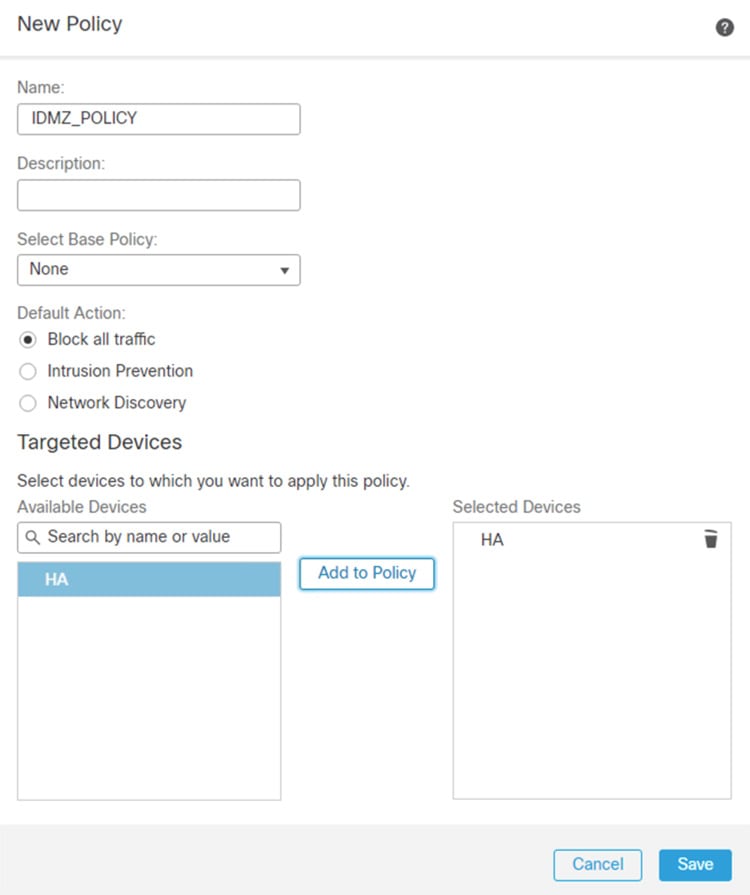
Step 4![]() Configure explicit Deny All rules between all zones (see Figure 3-5):
Configure explicit Deny All rules between all zones (see Figure 3-5):
a.![]() In FMC, navigate to Policies > Access Control.
In FMC, navigate to Policies > Access Control.
c.![]() Enter a unique Name and, optionally, a Description.
Enter a unique Name and, optionally, a Description.
d.![]() Specify the initial Default Action. Our intention is to Block all traffic which creates a policy with the Access Control: Block All Traffic default action.
Specify the initial Default Action. Our intention is to Block all traffic which creates a policy with the Access Control: Block All Traffic default action.
e.![]() Choose the Available Devices where you want to deploy the policy, then click Add to Policy to add the selected devices.
Choose the Available Devices where you want to deploy the policy, then click Add to Policy to add the selected devices.
Figure 3-5 FMC Access Rules Configuration
Note![]() Later sections in this chapter describe the configuration of firewall rules and policies for specific network applications and services.
Later sections in this chapter describe the configuration of firewall rules and policies for specific network applications and services.
IDMZ Network Interface Configuration
The following steps describe the configuration of the firewall interfaces for the IDMZ network. In the recommended architecture, the IDMZ network is segmented into several VLANs, each corresponding to a specific service in the IDMZ.
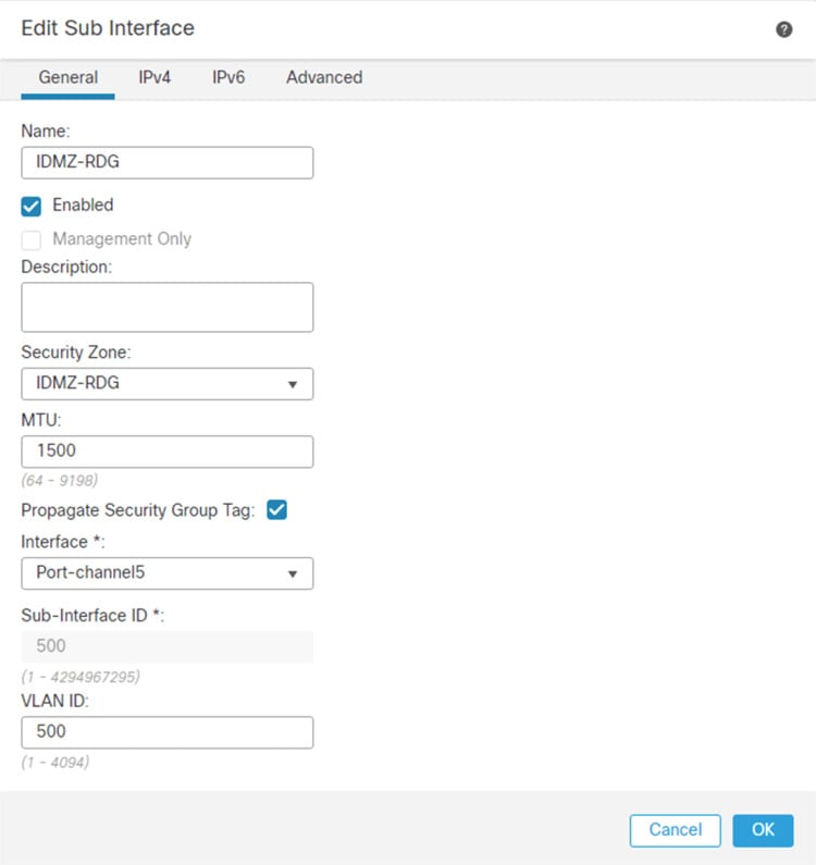
Step 1![]() Configure separate sub-interfaces for each network or application service hosted in the IDMZ (see Figure 3-6):
Configure separate sub-interfaces for each network or application service hosted in the IDMZ (see Figure 3-6):
Note![]() Before starting this procedure, confirm that the IDMZ-facing interface does not have an IP address, name, or security level configured. Otherwise, these configurations will be removed when the first sub-interface associated with that interface is created.
Before starting this procedure, confirm that the IDMZ-facing interface does not have an IP address, name, or security level configured. Otherwise, these configurations will be removed when the first sub-interface associated with that interface is created.
a.![]() In FMC, navigate to Devices > Device Management and Edit the device in which this VLAN applies.
In FMC, navigate to Devices > Device Management and Edit the device in which this VLAN applies.
b.![]() In the Interfaces tab, click Add Interfaces > Sub Interface.
In the Interfaces tab, click Add Interfaces > Sub Interface.
c.![]() Give a meaningful Name to the sub interface.
Give a meaningful Name to the sub interface.
d.![]() Assign a Security Zone for the sub interface.
Assign a Security Zone for the sub interface.
e.![]() Assign the Interface to which the sub interface belongs.
Assign the Interface to which the sub interface belongs.
f.![]() Assign the VLAN ID for the sub interface.
Assign the VLAN ID for the sub interface.
g.![]() Click OK to add the sub interface and then Save changes to the device.
Click OK to add the sub interface and then Save changes to the device.
h.![]() Define explicit Deny All rules for each sub-interface as described in the previous section to confirm isolation of each IDMZ service.
Define explicit Deny All rules for each sub-interface as described in the previous section to confirm isolation of each IDMZ service.
Figure 3-6 FMC Sub-interface Configuration
Industrial Zone Core Network Configuration
The following steps describe the configuration of the redundant network infrastructure between the Industrial Zone core network and the IDMZ firewall. The redundant core consisted of a pair of Cisco Catalyst 6500 switches in the VSS configuration.
Step 1![]() Enable Cisco StackWise Virtual on both switches and reload and configure Cisco StackWise Virtual link.
Enable Cisco StackWise Virtual on both switches and reload and configure Cisco StackWise Virtual link.
Note For information on VSS and detailed steps on performing this conversion process, refer to:
- https://www.cisco.com/c/en/us/td/docs/switches/lan/catalyst9500/software/release/16-9/configuration_guide/ha/b_169_ha_9500_cg/configuring_cisco_stackwise_virtual.html
Typical CLI output resulting from this conversion is shown below.
Step 2![]() Configure redundant EtherChannels between the VSS switch pair and the active and standby firewalls.
Configure redundant EtherChannels between the VSS switch pair and the active and standby firewalls.
a.![]() Configure two EtherChannel interfaces on the VSS switch pair, one for each firewall connection, using the commands below:
Configure two EtherChannel interfaces on the VSS switch pair, one for each firewall connection, using the commands below:
b.![]() Configure the members of both EtherChannel interfaces on the VSS switch pair using the commands below:
Configure the members of both EtherChannel interfaces on the VSS switch pair using the commands below:
IDMZ Server Network Configuration
The following steps describe the configuration of the redundant network infrastructure between the IDMZ switch and the IDMZ firewall.
Step 1![]() Configure EtherChannels between the IDMZ switch and the active and standby firewalls.
Configure EtherChannels between the IDMZ switch and the active and standby firewalls.
a.![]() Configure trunked EtherChannel interfaces on the IDMZ switch using the commands below:
Configure trunked EtherChannel interfaces on the IDMZ switch using the commands below:
b.![]() Configure the members of the EtherChannel interface on the IDMZ switch using the commands below:
Configure the members of the EtherChannel interface on the IDMZ switch using the commands below:
Step 2![]() Configure the IDMZ switch with VLANs for each service that will be hosted in the IDMZ, according to best practices for IDMZ segmentation. Assign switch ports to appropriate VLANs.
Configure the IDMZ switch with VLANs for each service that will be hosted in the IDMZ, according to best practices for IDMZ segmentation. Assign switch ports to appropriate VLANs.
Configuring Network Services
This section describes validated configurations for the network services that are allowed to traverse the IDMZ in order to provide necessary functions in both the Industrial and Enterprise Zones:
- Active Directory replication between Industrial and Enterprise Domain Controllers
- Time synchronization using NTP
- AAA Services
- Industrial and Enterprise ISE node synchronization traffic
- Tunneling of WLAN traffic between Industrial and Enterprise WLCs
Active Directory Configuration
Note This section shows only what is needed to enable replication through the IDMZ. For more generalized AD configuration steps, refer to the Deploying Identity Services within a Converged Plantwide Ethernet Architecture Design and Implementation Guide at:
Firewall Rules for AD Replication
The following steps describe the configuration of firewall rules to allow replication of AD services across the IDMZ.
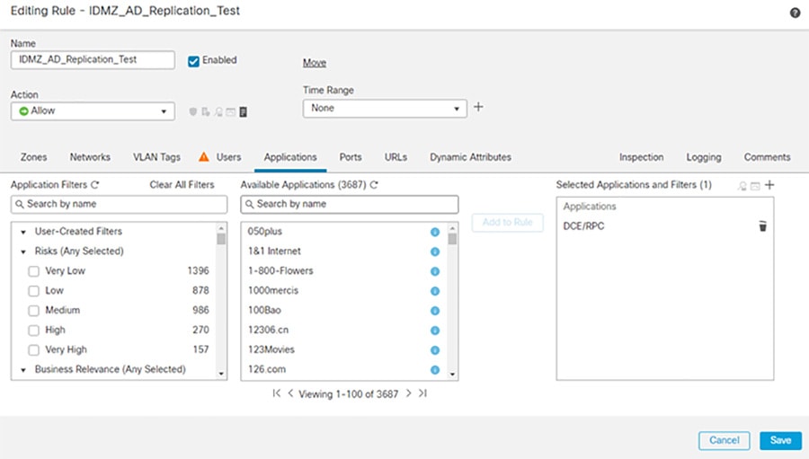
Step 1![]() Configure the firewall to allow RPC traffic between the Enterprise and Industrial AD data centers:
Configure the firewall to allow RPC traffic between the Enterprise and Industrial AD data centers:
a.![]() In FMC, navigate to Policies > Access Control.
In FMC, navigate to Policies > Access Control.
b.![]() Edit the rule assigned to the IDMZ firewall(s).
Edit the rule assigned to the IDMZ firewall(s).
d.![]() In the Zones tab, click Enterprise as the Source and Industrial as the Destination.
In the Zones tab, click Enterprise as the Source and Industrial as the Destination.
e.![]() In the Networks tab, enter the Enterprise AD IP Address object in the Source Network and the Industrial AD IP Address object in the Destination Network.
In the Networks tab, enter the Enterprise AD IP Address object in the Source Network and the Industrial AD IP Address object in the Destination Network.
f.![]() In the Applications tab, search for DCE/RPC and click Add to Rule.
In the Applications tab, search for DCE/RPC and click Add to Rule.
g.![]() In the Logging tab, click Log at Beginning of Connection to log connection events to FMC.
In the Logging tab, click Log at Beginning of Connection to log connection events to FMC.
h.![]() Repeat the rule in the reverse direction (Industrial to Enterprise)
Repeat the rule in the reverse direction (Industrial to Enterprise)
Figure 3-7 IDMZ AD Replication Access Control Rule
Step 2![]() Configure the firewall to allow additional protocols for replication ( Table 3-1 ). These protocols can be found in the Applications tab during policy creation.
Configure the firewall to allow additional protocols for replication ( Table 3-1 ). These protocols can be found in the Applications tab during policy creation.
Figure 3-8 Adding Additional Protocols for AD Replication
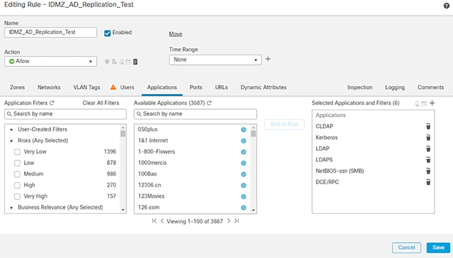
The access rules for AD replication are summarized in Table 3-1 ..
|
|
|
|
|
|---|---|---|---|
|
|
|||
|
|
Firewall Rules for AD Authentication in IDMZ
Certain firewall rules should be configured to allow hosts in the IDMZ to authenticate to the Enterprise AD. The examples of the IDMZ hosts are RD Gateway and Reverse Web Proxy servers, anti-virus, Windows Update and other services that are hosted in the IDMZ. These rules are listed in Table 3-2 .
NTP Configuration
This section describe configuration that is required to enable NTP in the CPwE IDMZ architecture.
NTP Synchronization for Network Devices
Network devices use NTP or sometimes SNTP to synchronize their clocks.
Note For best practices and sample configurations to enable NTP on network devices, refer to the product documentation at:
NTP Synchronization for Windows Servers
Microsoft Windows Servers use the Windows Time Service to synchronize their clocks. If a server is a domain member, it can receive time information directly from the DC. Otherwise, it can be configured to synchronize with a separate NTP server.
Note For more information and configuration guidelines, refer to Windows Time Service Technical Reference at:
NTP traffic should also be allowed between the Industrial and Enterprise DCs as part of the AD replication.
Firewall Rules for NTP Synchronization
The following steps describe the configuration of firewall rules to allow NTP traffic across the IDMZ (see Table 3-3 ):
Step 1![]() Configure the firewall to allow NTP synchronization between the Enterprise and Industrial Zone NTP servers, and between the Enterprise and Industrial DCs.
Configure the firewall to allow NTP synchronization between the Enterprise and Industrial Zone NTP servers, and between the Enterprise and Industrial DCs.
Step 2![]() Configure the firewall to allow synchronization (see Table 3-3 ) between IDMZ NTP clients (for example, Windows servers and IDMZ access/distribution switches) and the Enterprise Zone NTP server.
Configure the firewall to allow synchronization (see Table 3-3 ) between IDMZ NTP clients (for example, Windows servers and IDMZ access/distribution switches) and the Enterprise Zone NTP server.
|
|
|
|
|
|---|---|---|---|
|
|
|||
|
|
|||
|
|
The access rules can be applied using Cisco FDM or FMC (see Figure 3-8 in the Active Directory section as an example with FMC).
AAA Services Configuration
Some IDMZ network devices such as switches may need to communicate to the enterprise AAA servers to authenticate network administrators to allow remote login to the device. Table 3-4 lists the firewall rules that should be applied (depending on the AAA protocol in use):
|
|
|
|
|
|---|---|---|---|
|
|
ISE Configuration
As part of a distributed ISE setup, the nodes must be able to securely communicate to synchronize their policy configurations and centralize logs. Since ISE nodes exist in both the Industrial and Enterprise Zones, the following steps describe the configuration of the IDMZ firewall rules for the distributed ISE services across the IDMZ (see Table 3-5 ).
Note For information about ISE deployment in the CPwE, refer to the Deploying Identity Services within a Converged Plantwide Ethernet Architecture Design and Implementation Guide at:
Note For more information about ISE services and TCP/UDP ports that the distributed IES system may use, refer to:
- http://www.cisco.com/c/en/us/td/docs/security/ise/1-4/installation_guide/b_ise_InstallationGuide14/b_ise_InstallationGuide14_appendix_01010.html
Step 1![]() Configure the firewall to allow the ISE PSN in the Industrial Zone to synchronize its configuration with the PSN/PAN in the Enterprise Zone using HTTPS and JGroups protocols.
Configure the firewall to allow the ISE PSN in the Industrial Zone to synchronize its configuration with the PSN/PAN in the Enterprise Zone using HTTPS and JGroups protocols.
Step 2![]() Configure the firewall to allow the ISE PSN in the Industrial Zone to send its logs to the ISE MNT in the Enterprise Zone.
Configure the firewall to allow the ISE PSN in the Industrial Zone to send its logs to the ISE MNT in the Enterprise Zone.
|
|
|
|
|
|---|---|---|---|
|
|
|||
|
|
|||
|
|
HTTPS (TCP port 443) |
The access rules can be applied using Cisco FMC (see Figure 3-8 in the Active Directory section as an example).
Cisco Smart Software Manager (SSM) On-Prem Configuration
The following example will present a scenario and show the configuration steps to manage smart licensing in the Industrial Zone using an on-premise licensing server.
Note For details on the configuration of Cisco SSM On-Prem, refer to Cisco Smart Software Manager On-Prem Installation Guide at:
- https://www.cisco.com/web/software/286285517/147683/Smart_Software_Manager_On-Prem_7_Installation_Guide.pdf
Installing the Virtual Appliance
Step 1![]() Install the virtual appliance on ESXI:
Install the virtual appliance on ESXI:
b.![]() Log in to the VMWare vSphere web user interface console.
Log in to the VMWare vSphere web user interface console.
c.![]() From the side menu, right-click Virtual Machine and then choose Create/Register VM.
From the side menu, right-click Virtual Machine and then choose Create/Register VM.
d.![]() Choose Create a New Virtual Machine.
Choose Create a New Virtual Machine.
f.![]() In the Guest OS Family drop-down menu, choose Linux.
In the Guest OS Family drop-down menu, choose Linux.
g.![]() In the Guest OS Version drop-down menu, choose Other Linux (64-bit).
In the Guest OS Version drop-down menu, choose Other Linux (64-bit).
h.![]() Under CPUs, select the following settings: 2 or 4 Cores.
Under CPUs, select the following settings: 2 or 4 Cores.
i.![]() Under Memory, configure the supported memory size (8 gigabytes are recommended) for your deployment.
Under Memory, configure the supported memory size (8 gigabytes are recommended) for your deployment.
j.![]() Under New Hard Disk, configure 200 gigabytes (recommended).
Under New Hard Disk, configure 200 gigabytes (recommended).
k.![]() Under Network, allocate at least 1 virtual network interface card.
Under Network, allocate at least 1 virtual network interface card.
l.![]() Under SCSI Controller, select LSI Logic Parallel.
Under SCSI Controller, select LSI Logic Parallel.
m.![]() Under New CD/DVD Drive, select Datastore ISO file.
Under New CD/DVD Drive, select Datastore ISO file.
n.![]() Mount the ISO file for Cisco SSM.
Mount the ISO file for Cisco SSM.
o.![]() Once finished, power on the virtual appliance.
Once finished, power on the virtual appliance.
Step 2![]() Create an account on Cisco SSM:
Create an account on Cisco SSM:
a.![]() Open the Cisco SSM On-Prem Administration workspace using the URL: https://<ip_address>:8443/admin.
Open the Cisco SSM On-Prem Administration workspace using the URL: https://<ip_address>:8443/admin.
b.![]() When the login screen appears, login using these credentials: admin/CiscoAdmin!2345.
When the login screen appears, login using these credentials: admin/CiscoAdmin!2345.
Note![]() For security reasons, you will be required to immediately change the admin password or disable the account after you create a new local account to be used for administration.
For security reasons, you will be required to immediately change the admin password or disable the account after you create a new local account to be used for administration.
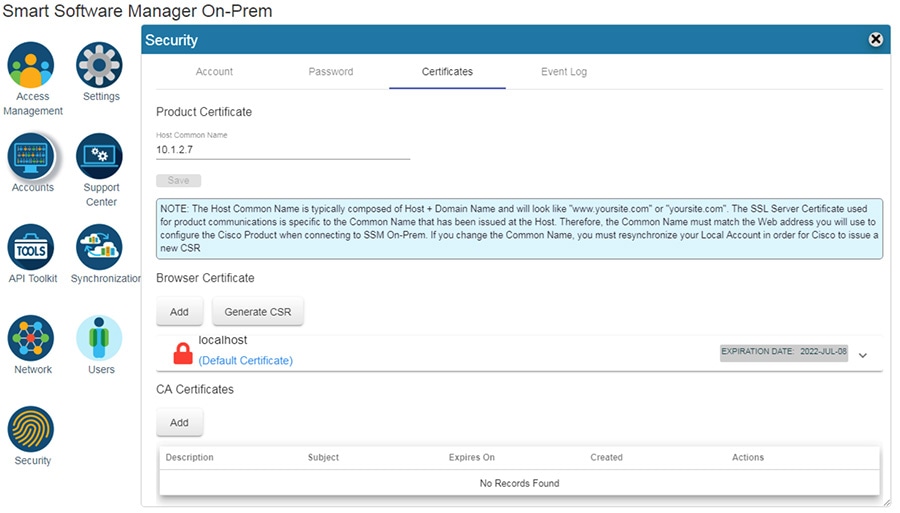
Step 3![]() Configure the Host Common Name:
Configure the Host Common Name:
The SSM ON-PREM-URL is the Common Name (CN) for the product. The CN is set in the Administration Workspace within the Security Widget, and is entered in the form of a Fully Qualified Domain Name (FQDN), hostname, or IP address of the SSM On-Prem. The CN must match what is used on the product as part of the call home configuration.
a.![]() In Cisco SSM, open the Security Widget.
In Cisco SSM, open the Security Widget.
b.![]() In the Certificates tab, enter the Host Common Name (IP Address).
In the Certificates tab, enter the Host Common Name (IP Address).
Figure 3-9 Adding Certificates to Cisco SSM On-Prem
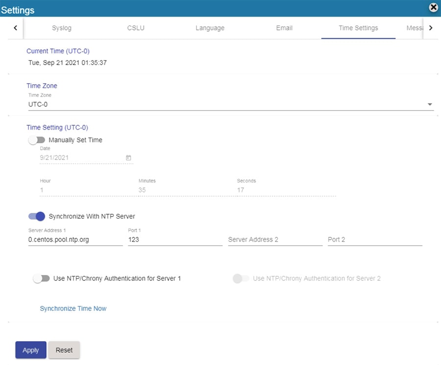
Step 4![]() Configure NTP settings.
Configure NTP settings.
Currently, you can set the time manually or allow it to synchronize with NTP. The time zone for your SSM On-Prem system can also be set with UTC+0 which allows for all the timestamps to be displayed in UTC time. UTC+offset enables the timestamp to be displayed in the system's local time.
a.![]() In Cisco SSM, open the Settings Widget and select the Time Settings tab.
In Cisco SSM, open the Settings Widget and select the Time Settings tab.
b.![]() Select Time Zone from the drop-down menu.
Select Time Zone from the drop-down menu.
c.![]() Turn on Synchronize with NTP server.
Turn on Synchronize with NTP server.
d.![]() Enter the NTP server address.
Enter the NTP server address.
Figure 3-10 Cisco SSM On-prem NTP Settings
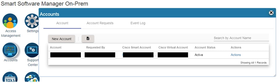
Step 5![]() Register On-Prem appliance with Cisco SSM Cloud.
Register On-Prem appliance with Cisco SSM Cloud.
It is necessary to register with Cisco Smart Software Manager (https://software.cisco.com) to use the Smart Software Manager On-Prem. To complete this process, ensure you meet the following requirements:
- Access to a Smart Account.
- A valid CCO User ID and Password to access the Smart Account.
- Either Smart Account or Virtual Account access to a Cisco Smart Account.
- Either an eligible existing or new Cisco Virtual Account.
With these requirements met, you will be able to proceed with the registration process by completing these steps to register (request) a local account.
a.![]() In Cisco SSM, open the Accounts widget.
In Cisco SSM, open the Accounts widget.
c.![]() Enter the required information:
Enter the required information:
e.![]() The Account request then is listed on the Account Requests tab in the Accounts widget.
The Account request then is listed on the Account Requests tab in the Accounts widget.
a.![]() In Cisco SSM, open the Accounts widget.
In Cisco SSM, open the Accounts widget.
b.![]() In the Account Requests tab, select Approve under the Actions drop-down menu.
In the Account Requests tab, select Approve under the Actions drop-down menu.
d.![]() When prompted, enter your CCO ID credentials to allow Cisco Smart Account/Virtual Account access on the Cisco SSM.
When prompted, enter your CCO ID credentials to allow Cisco Smart Account/Virtual Account access on the Cisco SSM.
f.![]() Verify that the local Account is listed as Active under the Accounts tab.
Verify that the local Account is listed as Active under the Accounts tab.
Figure 3-11 Account Management in Cisco SSM On-prem
Step 7![]() Synchronization with the Cloud.
Synchronization with the Cloud.
Online synchronization assumes there is an Internet connection to Cisco Smart Software Manager from SSM On-Prem. On each local Account, you can choose to perform either a Standard Synchronization Now action or Full Synchronization Now action. Manual synchronization is used when the customer network is not connected to the Internet. For details on that deployment see Smart Software Manager On-Prem Installation Guide.
a.![]() In Cisco SSM, click the Synchronization Widget.
In Cisco SSM, click the Synchronization Widget.
b.![]() On the local Account, under Actions, select Standard Syncronization Now or Full Synchronization Now.
On the local Account, under Actions, select Standard Syncronization Now or Full Synchronization Now.
c.![]() Enter your Cisco Smart Account credentials.
Enter your Cisco Smart Account credentials.
Configuring Firewall Rules for Cisco SSM On-Prem
The following steps describe the configuration of firewall rules for the Cisco SSM On-Prem to allow Industrial Clients to get licensed behind the IDMZ.
Note![]() If using a web proxy in the IDMZ a rule should already exist in the firewall for the web proxy to forward all HTTPS towards the enterprise zone.
If using a web proxy in the IDMZ a rule should already exist in the firewall for the web proxy to forward all HTTPS towards the enterprise zone.
Step 1![]() Configure the firewall to allow Cisco SSM On-Prem to synchronize with the Cloud and for clients to access Management portal from Enterprise zone (see Table 3-6 ).
Configure the firewall to allow Cisco SSM On-Prem to synchronize with the Cloud and for clients to access Management portal from Enterprise zone (see Table 3-6 ).
|
|
|
|
|
|---|---|---|---|
Step 2![]() Configure firewall to allow Industrial Clients to register with Cisco SSM On-Prem (see Table 3-7 ).
Configure firewall to allow Industrial Clients to register with Cisco SSM On-Prem (see Table 3-7 ).
|
|
|
|
|
|---|---|---|---|
WSUS Configuration
This section describe configuration that is required to enable WSUS in the CPwE IDMZ architecture.
Deploying WSUS
For information and configuration guidelines for planning and deploying WSUS refer to:
- https://docs.microsoft.com/en-us/windows-server/administration/windows-server-update-services/deploy/deploy-windows-server-update-services
In this design guide, the WSUS server in the IDMZ was set to automatically collect updates from Microsoft Update and for Industrial zone updates to be installed manually.
Firewall Rules for WSUS
To get updates from Microsoft Update, the WSUS server uses port 443 for the HTTPS protocol. It is assumed for this design guide that all traffic traversing port 80/443 will do so through a web proxy and therefore no additional firewall rules need to be deployed for the outbound interface.
For clients connecting from the Industrial zone to the WSUS, the following is required:
Step 1![]() Configure the firewall to allow Windows clients to pull updates from the WSUS (see Table 3-8 ).
Configure the firewall to allow Windows clients to pull updates from the WSUS (see Table 3-8 ).
|
|
|
|
|
|---|---|---|---|
Configuring Data Transfer through IDMZ
This section describes validated configurations that allow essential data to traverse the IDMZ between the Enterprise and Industrial Zones as described in System Design Considerations .
The following configuration steps are covered in this section:
- PI-to-PI Interface configuration and firewall rules for FactoryTalk Historian data transfer
- Firewall rules for secure managed file transfer using SolarWinds Serv-U solution as an example
FactoryTalk Historian Data Transfer Configuration
This section provides necessary steps to enable FactoryTalk Historian data transfer across the IDMZ.
Note For general information about FactoryTalk Historian installation and configuration, refer to:
PI to PI Interface Configuration
An overview of PI-to-PI installation and configuration steps is provided here.
Note For complete information, refer to the following documents:
–![]() http://literature.rockwellautomation.com/idc/groups/literature/documents/in/h2h-in001_-en-e.pdf
http://literature.rockwellautomation.com/idc/groups/literature/documents/in/h2h-in001_-en-e.pdf
–![]() http://literature.rockwellautomation.com/idc/groups/literature/documents/um/h2h-um001_-en-e.pdf
http://literature.rockwellautomation.com/idc/groups/literature/documents/um/h2h-um001_-en-e.pdf
Step 1![]() Install the FactoryTalk Services platform on the PI to PI server in the IDMZ.
Install the FactoryTalk Services platform on the PI to PI server in the IDMZ.
Step 2![]() Install FactoryTalk Historian To Historian Interface (PI-to-PI Interface) on the PI-to-PI server in the IDMZ.
Install FactoryTalk Historian To Historian Interface (PI-to-PI Interface) on the PI-to-PI server in the IDMZ.
Step 3![]() Obtain a PI-to-PI license activation file and activate the interface using FactoryTalk Activation Manager. Assign the license activation to the target server using the FactoryTalk Administration Console.
Obtain a PI-to-PI license activation file and activate the interface using FactoryTalk Activation Manager. Assign the license activation to the target server using the FactoryTalk Administration Console.
Step 4![]() Create a PI-to-PI Interface Instance in the Interface Configuration Utility (ICU).
Create a PI-to-PI Interface Instance in the Interface Configuration Utility (ICU).
a.![]() Go to Start > All Programs > Rockwell Software > FactoryTalk Historian SE > Interface Configuration Utility. The ICU dialog box appears.
Go to Start > All Programs > Rockwell Software > FactoryTalk Historian SE > Interface Configuration Utility. The ICU dialog box appears.
b.![]() Select Interface > New Windows Interface Instance from EXE. Click Browse to locate the executable file for the PI-to-PI Interface, for example C:\Program Files (x86)\Rockwell Software\FactoryTalk Historian\PIPC\Interfaces\FTPItoPI\FTPItoPI.exe.
Select Interface > New Windows Interface Instance from EXE. Click Browse to locate the executable file for the PI-to-PI Interface, for example C:\Program Files (x86)\Rockwell Software\FactoryTalk Historian\PIPC\Interfaces\FTPItoPI\FTPItoPI.exe.
c.![]() Under Host PI Server/Collective, select the Enterprise Zone Historian server. Complete the following information and then click Add.
Under Host PI Server/Collective, select the Enterprise Zone Historian server. Complete the following information and then click Add.
|
|
|
d.![]() Under Scan Classes, create one scan class at a 15 second frequency.
Under Scan Classes, create one scan class at a 15 second frequency.
e.![]() In the PI-to-PI sub menu, go to the Required tab, and type the Source host, which is the Industrial Zone FactoryTalk Historian SE server. It may be either a DNS name or an IP address.
In the PI-to-PI sub menu, go to the Required tab, and type the Source host, which is the Industrial Zone FactoryTalk Historian SE server. It may be either a DNS name or an IP address.
f.![]() In the Service tab, click Create.
In the Service tab, click Create.
Step 5![]() Create a Test Target Point on the Enterprise FactoryTalk Historian server.
Create a Test Target Point on the Enterprise FactoryTalk Historian server.
a.![]() Go to Start > All Programs > Rockwell Software > FactoryTalk Historian SE > System Management Tools. The System Management Tools dialog box appears.
Go to Start > All Programs > Rockwell Software > FactoryTalk Historian SE > System Management Tools. The System Management Tools dialog box appears.
b.![]() Under Collectives and Servers, select the Enterprise Zone FactoryTalk Historian server.
Under Collectives and Servers, select the Enterprise Zone FactoryTalk Historian server.
c.![]() Under System Management Tools, select Points > Point Builder. Click the toolbar icon to create anew point.
Under System Management Tools, select Points > Point Builder. Click the toolbar icon to create anew point.
d.![]() In the General tab, complete the following information:
In the General tab, complete the following information:
|
|
|
e.![]() In the Classic tab, complete the following information:
In the Classic tab, complete the following information:
|
|
|
Step 6![]() In order for the PI-to-PI Interface to be allowed to interact with either one of the FactoryTalk Historian Servers, a trust has to be created for its executable. Configure an application trust for FTPITOPI.exe with the PIadmin user on the Enterprise FactoryTalk Historian server.
In order for the PI-to-PI Interface to be allowed to interact with either one of the FactoryTalk Historian Servers, a trust has to be created for its executable. Configure an application trust for FTPITOPI.exe with the PIadmin user on the Enterprise FactoryTalk Historian server.
a.![]() On the Enterprise FactoryTalk Historian SE Server, go to Start > All Programs > Rockwell Software > FactoryTalk Historian SE > System Management Tools. The System Management Tools dialog box appears.
On the Enterprise FactoryTalk Historian SE Server, go to Start > All Programs > Rockwell Software > FactoryTalk Historian SE > System Management Tools. The System Management Tools dialog box appears.
b.![]() Under Collectives and Servers, select the Enterprise Zone FactoryTalk Historian server.
Under Collectives and Servers, select the Enterprise Zone FactoryTalk Historian server.
c.![]() Under System Management Tools, select Security > Mappings & Trust. Go to the Trusts tab. Click New Trust in the toolbar and then click Advanced.
Under System Management Tools, select Security > Mappings & Trust. Go to the Trusts tab. Click New Trust in the toolbar and then click Advanced.
d.![]() In the Add New Trust dialog box, provide the following information:
In the Add New Trust dialog box, provide the following information:
|
|
|
IP address of the server with the PI to PI interface installed |
|
Step 7![]() Configure an application trust for FTPITOPI.exe with the PIadmin user on the Industrial Zone FactoryTalk Historian server. The steps are same as for the Enterprise server above.
Configure an application trust for FTPITOPI.exe with the PIadmin user on the Industrial Zone FactoryTalk Historian server. The steps are same as for the Enterprise server above.
Step 8![]() Start and verify the PI-to-PI Interface:
Start and verify the PI-to-PI Interface:
a.![]() Go to Start > All Programs > Rockwell Software > FactoryTalk Historian SE > Interface Configuration Utility. The ICU dialog box appears.
Go to Start > All Programs > Rockwell Software > FactoryTalk Historian SE > Interface Configuration Utility. The ICU dialog box appears.
b.![]() Under Interface, select the interface you have just created. On the toolbar, click Start. The status of the interface at the bottom of the dialog box should change to Running.
Under Interface, select the interface you have just created. On the toolbar, click Start. The status of the interface at the bottom of the dialog box should change to Running.
c.![]() To verify that the PI-to-PI Interface is working properly, you need to check whether the current values of the tag at the Industrial Zone and Enterprise Zone FactoryTalk Historian servers match each other. This can be done using System Management Tools by selecting Data > Current Values and searching for the tag.
To verify that the PI-to-PI Interface is working properly, you need to check whether the current values of the tag at the Industrial Zone and Enterprise Zone FactoryTalk Historian servers match each other. This can be done using System Management Tools by selecting Data > Current Values and searching for the tag.
Firewall Rules for FactoryTalk Historian Data Transfer
The following steps describe the configuration of firewall rules to allow FactoryTalk Historian data across the IDMZ using a PI-to-PI Interface (see Table 3-9 ).
Step 1![]() Configure firewall to allow incoming connections from the Industrial Zone Historian to the PI-to-PI server using PI Server Client protocol (TCP port 5450) and RPC (TCP port 135).
Configure firewall to allow incoming connections from the Industrial Zone Historian to the PI-to-PI server using PI Server Client protocol (TCP port 5450) and RPC (TCP port 135).
Step 2![]() Configure firewall to allow incoming connections from the Enterprise Zone Historian to the PI-to-PI server on the same ports.
Configure firewall to allow incoming connections from the Enterprise Zone Historian to the PI-to-PI server on the same ports.
Step 3![]() Configure firewall to allow incoming connections from the PI-to-PI server to both Historians.
Configure firewall to allow incoming connections from the PI-to-PI server to both Historians.
|
|
|
|
|
|---|---|---|---|
|
|
|||
|
|
|||
|
|
In addition to Steps 1-3, the PI-to-PI server needs to authenticate to the DC through the firewall, therefore it should be included in the list of IDMZ hosts that are allowed to do so (see Active Directory Configuration sections).
Secure File Transfer Configuration
To facilitate secure file transfer (SFT) between the Enterprise and Industrial Zones via the IDMZ, many implementations are available to choose from.
In the context of the IDMZ, a client based in the Industrial Zone can upload to and download files from the SFT Server (located in the Enterprise Zone) via the Gateway (located in the IDMZ). As per IDMZ best practices, no direct connections are opened between the Industrial and Enterprise Zones, and no data resides permanently in the IDMZ. In a similar manner, an enterprise client can upload to and download files from the Industrial SFT Server via the IDMZ Gateway.
The following steps describe the configuration of firewall rules to allow SFT services across the IDMZ, using FTP as the mode of transport (see Table 3-10 and Table 3-11 ):
Step 1![]() Configure the firewall to allow incoming client connections from the Industrial Zone clients to the IDMZ-based gateway server. The clients use the FTP protocol, which can be configured in an application rule.
Configure the firewall to allow incoming client connections from the Industrial Zone clients to the IDMZ-based gateway server. The clients use the FTP protocol, which can be configured in an application rule.
Step 2![]() Configure the firewall to allow incoming client connections from Enterprise Zone clients to the IDMZ-based gateway server. The clients use the FTP protocol.
Configure the firewall to allow incoming client connections from Enterprise Zone clients to the IDMZ-based gateway server. The clients use the FTP protocol.
Note![]() If using SFTP for file transfer, the connection must be decrypted so the file contents can be checked. For information on doing decryption using Cisco FTD. See Understanding Traffic Decryption at:
If using SFTP for file transfer, the connection must be decrypted so the file contents can be checked. For information on doing decryption using Cisco FTD. See Understanding Traffic Decryption at:
https://www.cisco.com/c/en/us/td/docs/security/firepower/70/configuration/guide/fpmc-config-guide-v70/understanding_traffic_decryption.html
|
|
|
|
|
|---|---|---|---|
|
|
|
|
|
|
|
|---|---|---|---|
|
|
The access rules can be applied using Cisco FMC web interface (see Figure 3-8 in the Active Directory section as an example).
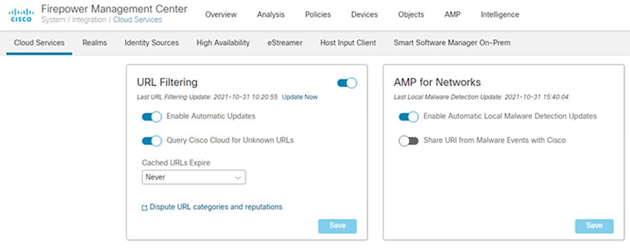
Step 3![]() Connect to the AMP Cloud.
Connect to the AMP Cloud.
a.![]() In FMC, navigate to System > Integration.
In FMC, navigate to System > Integration.
c.![]() Select Enable Automatic Local Malware Detection Updates to stay up to date with the latest signatures updates.
Select Enable Automatic Local Malware Detection Updates to stay up to date with the latest signatures updates.
d.![]() Configure the firewall to allow outgoing connections from the IDMZ to the cloud. By default, Firepower uses port 443/HTTPS to communicate with the AMP public cloud to obtain file disposition date. Note: If using a web proxy in the IDMZ, forward all traffic through the web proxy.
Configure the firewall to allow outgoing connections from the IDMZ to the cloud. By default, Firepower uses port 443/HTTPS to communicate with the AMP public cloud to obtain file disposition date. Note: If using a web proxy in the IDMZ, forward all traffic through the web proxy.
Figure 3-12 FMC URL Filtering Updates
a.![]() In FMC, navigate to Policies > Access Control > Malware & File.
In FMC, navigate to Policies > Access Control > Malware & File.
c.![]() Give a Name and optional Description. Click Save.
Give a Name and optional Description. Click Save.
e.![]() In the Action drop down list, choose Block Files.
In the Action drop down list, choose Block Files.
f.![]() Under File Type Categories, click all categories you wish to block and click Add.
Under File Type Categories, click all categories you wish to block and click Add.
Note Note: The order of precedence of file-rule action is:
i.![]() In the Action drop down list, choose Block Malware.
In the Action drop down list, choose Block Malware.
Note![]() Block Malware rules allow you to calculate the SHA-256 hash value of specific file types, query the AMP cloud to determine if files traversing your network contain malware, then block files that represent threats.
Block Malware rules allow you to calculate the SHA-256 hash value of specific file types, query the AMP cloud to determine if files traversing your network contain malware, then block files that represent threats.
j.![]() Under File Type Categories, click all categories you wish to allow into the Industrial zone and click Add.
Under File Type Categories, click all categories you wish to allow into the Industrial zone and click Add.
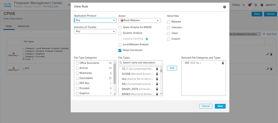
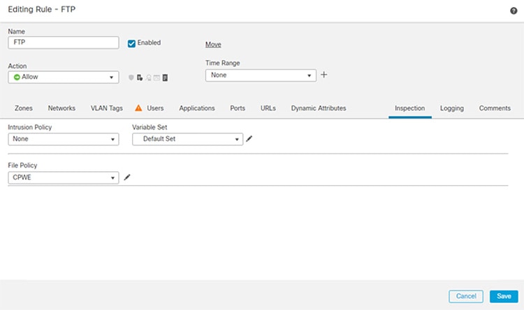
Step 5![]() Add File Policy to Access Control Rule:
Add File Policy to Access Control Rule:
a.![]() In FMC, navigate to Policies > Access Control.
In FMC, navigate to Policies > Access Control.
b.![]() Edit the access control rule created earlier for allowing FTP.
Edit the access control rule created earlier for allowing FTP.
c.![]() Go to the Inspection tab, and in the File Policy drop down menu, choose the File Policy created in Step 4.
Go to the Inspection tab, and in the File Policy drop down menu, choose the File Policy created in Step 4.
e.![]() Save the policy and Deploy changes.
Save the policy and Deploy changes.
Figure 3-14 Editing Access Rule in FMC for FTP
Configuring Remote Access Services
This section describes validated configurations that allow remote users securely access desktop applications that are hosted in the Industrial Zone via the IDMZ.
The following configuration steps are covered in this section:
–![]() Client-based SSL VPN (Cisco AnyConnect) to the Enterprise firewall
Client-based SSL VPN (Cisco AnyConnect) to the Enterprise firewall
SSL VPN Configuration
This section provides configuration steps for the firewall to implement SSL VPN access for remote users.
https://www.cisco.com/c/en/us/td/docs/security/firepower/670/configuration/guide/fpmc-config-guide-v67/firepower_threat_defense_remote_access_vpns.html
Note Additional information about VPN configuration on the FTD can be found in Remote Access VPNs for Firepower Threat Defense at:
- https://www.cisco.com/c/en/us/td/docs/security/firepower/670/configuration/guide/fpmc-config-guide-v67/firepower_threat_defense_remote_access_vpns.html
Client-based SSL VPN Configuration
The following steps describe the configuration of client-based (Cisco AnyConnect) SSL VPN on the Enterprise edge firewall to allow remote access from the Internet.
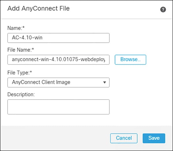
Step 1![]() Load the AnyConnect client images to the FMC (images are downloaded from Cisco):
Load the AnyConnect client images to the FMC (images are downloaded from Cisco):
a.![]() In FMC, navigate to Objects > Object Management.
In FMC, navigate to Objects > Object Management.
b.![]() Click on VPN > AnyConnect File.
Click on VPN > AnyConnect File.
d.![]() Give a meaningful name to the AnyConnect File, add the headend package using the Browse button, and on the File Type drop down menu click AnyConnect Client Image.
Give a meaningful name to the AnyConnect File, add the headend package using the Browse button, and on the File Type drop down menu click AnyConnect Client Image.
e.![]() Repeat for all packages that have been downloaded (Windows, Mac, etc.).
Repeat for all packages that have been downloaded (Windows, Mac, etc.).
Figure 3-15 Loading AnyConnec Files in FMC
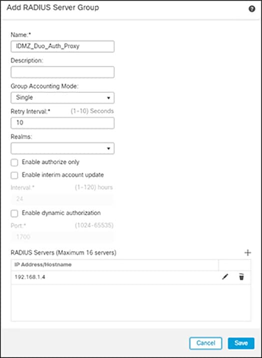
Step 2![]() Add Duo Authentication Proxy as RADIUS Server in FMC:
Add Duo Authentication Proxy as RADIUS Server in FMC:
a.![]() In FMC, navigate to Objects > Object Management > AAA Server > RADIUS Server Group.
In FMC, navigate to Objects > Object Management > AAA Server > RADIUS Server Group.
b.![]() Click Add RADIUS Server Group.
Click Add RADIUS Server Group.
c.![]() Give a meaningful name to the server group and add the IP Address/Hostname where the Duo Authentication Proxy resides.
Give a meaningful name to the server group and add the IP Address/Hostname where the Duo Authentication Proxy resides.
Figure 3-16 Add RADIUS Server to FMC
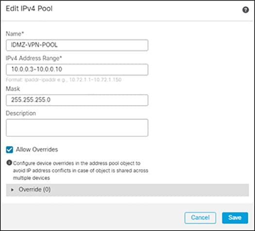
Step 3![]() Create VPN Address Pool:
Create VPN Address Pool:
a.![]() In FMC, navigate to Objects > Object Management > Address Pools > IPv4 Pools.
In FMC, navigate to Objects > Object Management > Address Pools > IPv4 Pools.
c.![]() Give a meaningful name to the address pool and add the IPv4 Address Range you wish to assign to VPN users.
Give a meaningful name to the address pool and add the IPv4 Address Range you wish to assign to VPN users.
Figure 3-17 Editing IPv4 address pool for remotes access VPN
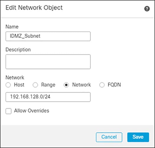
Step 4![]() Add a VPN Split Tunnel List:
Add a VPN Split Tunnel List:
a.![]() In FMC, navigate to Objects > Object Management > Network.
In FMC, navigate to Objects > Object Management > Network.
b.![]() In the Add Network drop down, click Add Object.
In the Add Network drop down, click Add Object.
c.![]() Add the Network subnet that you would like roaming users to reach through the tunnel. In this design guide, roaming users will only use the VPN tunnel to access private subnets.
Add the Network subnet that you would like roaming users to reach through the tunnel. In this design guide, roaming users will only use the VPN tunnel to access private subnets.
d.![]() Repeat for each subnet or host that you would like to be reachable by roaming users.
Repeat for each subnet or host that you would like to be reachable by roaming users.
Figure 3-18 Configuring Network Range for Split Tunnel Configuration
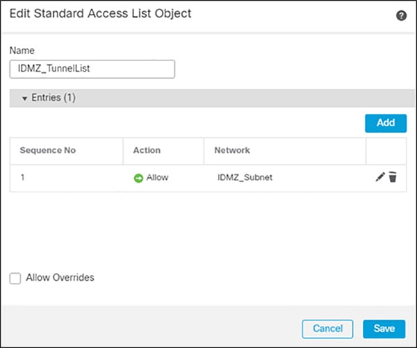
a.![]() Navigate to Objects > Object Management > Access List > Standard.
Navigate to Objects > Object Management > Access List > Standard.
b.![]() Click Add Standard Access List.
Click Add Standard Access List.
c.![]() Give a meaningful name to the split tunnel and add the network object(s) from the previous steps.
Give a meaningful name to the split tunnel and add the network object(s) from the previous steps.
Figure 3-19 Editing Access List for VPN Access
Step 5![]() Complete the AnyConnect VPN wizard:
Complete the AnyConnect VPN wizard:
a.![]() In FMC, navigate to Devices > VPN > Remote Access.
In FMC, navigate to Devices > VPN > Remote Access.
c.![]() Add a meaningful name and click the FTD(s) that this policy will apply. Click Next.
Add a meaningful name and click the FTD(s) that this policy will apply. Click Next.
d.![]() Under Authentication Server, choose the Duo Authentication Proxy that was configured in a previous step.
Under Authentication Server, choose the Duo Authentication Proxy that was configured in a previous step.
e.![]() Add the IPv4 Address Pool that was created for VPN users.
Add the IPv4 Address Pool that was created for VPN users.
f.![]() Under Group Policy, click +.
Under Group Policy, click +.
g.![]() Give a meaningful name to the policy.
Give a meaningful name to the policy.
h.![]() In the General > DNS/WINS tab, add the DNS server for the internal network. Note: If this network object does not already exist in FMC, it can be added using the + button.
In the General > DNS/WINS tab, add the DNS server for the internal network. Note: If this network object does not already exist in FMC, it can be added using the + button.
i.![]() In the General > Split Tunneling tab, click IPv4 Split Tunneling drop down and choose Tunnel networks specified below. Repeat for IPv6 if applicable.
In the General > Split Tunneling tab, click IPv4 Split Tunneling drop down and choose Tunnel networks specified below. Repeat for IPv6 if applicable.
j.![]() Under Standard Access List, choose the Split Tunneling list that was created in a previous step. This will ensure that only the traffic that has been specified will use the tunnel.
Under Standard Access List, choose the Split Tunneling list that was created in a previous step. This will ensure that only the traffic that has been specified will use the tunnel.
k.![]() Under DNS Request Split Tunneling, click DNS Requests drop down and choose Send only specified domains over tunnel.
Under DNS Request Split Tunneling, click DNS Requests drop down and choose Send only specified domains over tunnel.
l.![]() Enter the domain list for the internal network. All other DNS requests will be sent to Umbrella (when configured).
Enter the domain list for the internal network. All other DNS requests will be sent to Umbrella (when configured).
m.![]() Click Next on the Remote Access VPN wizard.
Click Next on the Remote Access VPN wizard.
n.![]() Select the AnyConnect Client images that were uploaded in a previous step. Click Next.
Select the AnyConnect Client images that were uploaded in a previous step. Click Next.
o.![]() On the Interface group/Security Zone drop-down menu, choose the FTD interface that users will access for VPN connections.
On the Interface group/Security Zone drop-down menu, choose the FTD interface that users will access for VPN connections.
p.![]() In the Certificate Enrollment drop-down menu, choose the device certificate that will be used to authenticate the VPN gateway. Note: This design guide used a self-signed certificate that was created using the + button.
In the Certificate Enrollment drop-down menu, choose the device certificate that will be used to authenticate the VPN gateway. Note: This design guide used a self-signed certificate that was created using the + button.
r.![]() Validate the policy information and click Finish.
Validate the policy information and click Finish.
s.![]() Click Deploy to send remote access policy to the FTD.
Click Deploy to send remote access policy to the FTD.
Note![]() While out of scope for this guide, it is recommended to create access control rules on the firewall to limit access to VPN users. This can be achieved by using the IPv4 address pool reserved for VPN users and creating an allow list of services they should be able to reach on the network.
While out of scope for this guide, it is recommended to create access control rules on the firewall to limit access to VPN users. This can be achieved by using the IPv4 address pool reserved for VPN users and creating an allow list of services they should be able to reach on the network.
Microsoft Remote Desktop Gateway Configuration
The following example will present a scenario and show the configuration steps to achieve the requirements. It is assumed that the user has completed the initial setup of the RD Gateway role server in the IDMZ.
Note For details on the configuration of the RD Gateway feature on the Microsoft Windows Server, refer to Deploying Remote Desktop Gateway Step-by-Step Guide at:
Defining User Groups and Remote Access Rules
In our scenario, we have the following actors shown in Table 3-12 that will be assigned to the following Active Directory User Groups:
We will now define the Industrial Zone assets each AD user group will be allowed to access through the RD Gateway. Duo Authentication for Remote Desktop Gateway adds two-factor authentication to your RemoteApp Access logons and blocks any connections to your Remote Desktop Gateway server(s) from users who have not completed two-factor authentication when all connection requests are proxied through a Remote Desktop Gateway. Users automatically receive a 2FA prompt in the form of a push request in Duo Mobile or a phone call when logging in. This configuration does not support passcodes or inline self-enrollment.
Installing Duo’s RD Gateway plugin disables Remote Desktop Connection Authorization Policies (RD CAP) and Resource Authorization Policies (RD RAP). The CAPs and RAPs become inaccessible from the Remote Desktop Gateway Manager and previously configured policy settings are ignored by Remote Desktop Gateway. If operational requirements mandate continued use of RD CAPs/RAPs, you may want to consider installing Duo for Windows Logon at your RDS session hosts instead.
With this in mind, the remainder of the document will focus on the use of RD CAPs/RAPs. For prerequisites, installation instructions and troubleshooting tips for MFA with the RD gateway, see Duo Authentication for Microsoft Remote Desktop Gateway on Windows 2012 or later.
Now that we have defined the computer groups, users, user groups and what each group is authorized to access through the RD Gateway, we will show the configuration steps to meet these requirements.
It is worthwhile mentioning that FactoryTalk Security is discussed in this guide as a means to secure Rockwell Automation applications. Application security can also be achieved by limiting the applications available to each user or user group(s) desktop.
Configuring Active Directory
Before we configure the RD Gateway, we want to leverage the AD users and groups we have planned in the previous section so configuring these users within AD is our first step. The section assumes the reader has some familiarity with AD and how to create users, user groups and computer groups.
Note For more detailed information on the Microsoft AD functionality, refer to Active Directory Users and Computers at:
- https://docs.microsoft.com/en-us/previous-versions/windows/it-pro/windows-server-2008-R2-and-2008/cc754217(v=ws.11)?redirectedfrom=MSDN
Step 1![]() Create AD users and groups as described in Table 17 using the Active Directory Users and Computers management console.
Create AD users and groups as described in Table 17 using the Active Directory Users and Computers management console.
a.![]() Create AD users groups (Operators, Engineers, Maintenance, OEM1, OEM2 and ProdAdmins).
Create AD users groups (Operators, Engineers, Maintenance, OEM1, OEM2 and ProdAdmins).
b.![]() Create AD users and assign to the corresponding groups.
Create AD users and assign to the corresponding groups.
c.![]() Create an AD group that will be allowed to access Industrial Zone assets. In our example it will be named IDMZ RD Gateway Users.
Create an AD group that will be allowed to access Industrial Zone assets. In our example it will be named IDMZ RD Gateway Users.
d.![]() Add user groups from Step 1 (Engineers, Maintenance, OEM1, OEM2 and ProdAdmins) to the IDMZ RD Gateway Users group.
Add user groups from Step 1 (Engineers, Maintenance, OEM1, OEM2 and ProdAdmins) to the IDMZ RD Gateway Users group.
–![]() Note that the Operators group will not be added since our policy does not allow remote access for operators.
Note that the Operators group will not be added since our policy does not allow remote access for operators.
Step 2![]() Create computer groups as described in Table 3-12 .
Create computer groups as described in Table 3-12 .
a.![]() Create IDMZ RD Gateway Remote Hosts computer group.
Create IDMZ RD Gateway Remote Hosts computer group.
b.![]() Add the IACS Terminal Server (TERM01) to the IDMZ RD Gateway Remote Hosts group.
Add the IACS Terminal Server (TERM01) to the IDMZ RD Gateway Remote Hosts group.
c.![]() Create IACS Hosts computer group that will contain Industrial Zone assets for remote access.
Create IACS Hosts computer group that will contain Industrial Zone assets for remote access.
d.![]() Add the appropriate servers to the IACS Hosts group per Table 3-12 . The exact list of servers for remote access will depend on the environment and business needs.
Add the appropriate servers to the IACS Hosts group per Table 3-12 . The exact list of servers for remote access will depend on the environment and business needs.
Configuring RD Gateway Policies
After defining remote access rules and creating corresponding users, user groups and computer groups in the AD, the administrator should configure the RD Gateway policies (CAPs and RAPs) to match the rules.
In our example, we will configure two CAPs and RAPs to support the scenario in Table 3-12 .
- A CAP and RAP will exist to allow users to connect to the terminal server in the Industrial Zone.
- A CAP and RAP will also exist to allow Production Administrators and Engineers to access all the IACS servers.
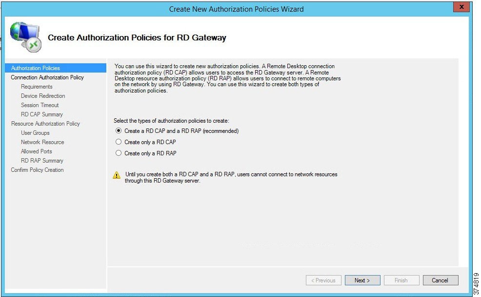
Step 1![]() Configure IDMZ RDG Remote Host CAP using the RDG Manager. The IDMZ RDG Remote Host scenario will allow the authorized users to access the terminal server in the Industrial Zone.
Configure IDMZ RDG Remote Host CAP using the RDG Manager. The IDMZ RDG Remote Host scenario will allow the authorized users to access the terminal server in the Industrial Zone.
a.![]() From the RDG Manager, the Policies folder and select Create New Authorization Policies. In the dialog box (see Figure 3-20), select Create RD CAP and a RD RAP (recommended) and then click Next.
From the RDG Manager, the Policies folder and select Create New Authorization Policies. In the dialog box (see Figure 3-20), select Create RD CAP and a RD RAP (recommended) and then click Next.
b.![]() Name the CAP as IDMZ RDG CAP and then click Next to proceed to the Requirements page.
Name the CAP as IDMZ RDG CAP and then click Next to proceed to the Requirements page.
c.![]() Each CAP allows the administrator to select a Password, a Smartcard or both as an authentication method. In our example, we are allowing the user to use a password (see Figure 3-21).
Each CAP allows the administrator to select a Password, a Smartcard or both as an authentication method. In our example, we are allowing the user to use a password (see Figure 3-21).
Figure 3-21 CAP Requirements - Authentication Method
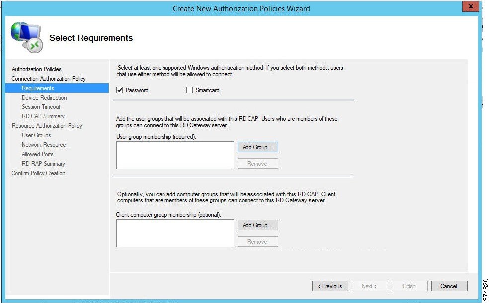
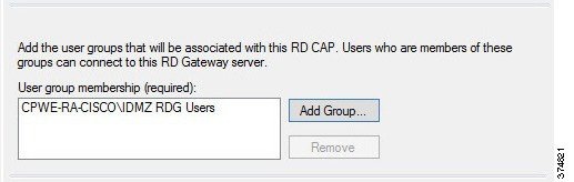
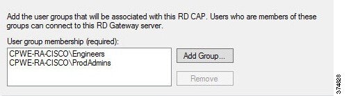
d.![]() With the Password option selected, we will now add user groups that will be associated with this CAP. Click Add Group in the User Group Membership section. In the Selection Group dialog box, find and select IDMZ RDG Users group to associate it with the RDG CAP (see Figure 3-22). Click Next.
With the Password option selected, we will now add user groups that will be associated with this CAP. Click Add Group in the User Group Membership section. In the Selection Group dialog box, find and select IDMZ RDG Users group to associate it with the RDG CAP (see Figure 3-22). Click Next.
Figure 3-22 CAP Requirements—User Group
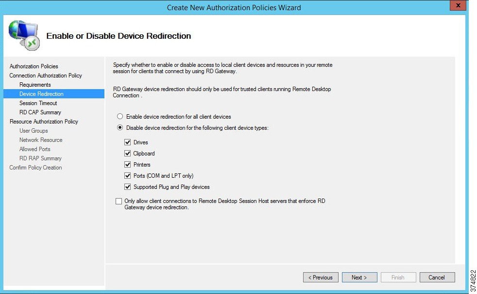
e.![]() The CAP also allows the administrator to enable or disable device redirection. Device redirection controls access to devices and resources on a client computer in RDP sessions. For instance, Drives redirection specifies whether to prevent the mapping of client drives in an RDP session. For our example, we will disable device redirection to bolster security (see Figure 3-23). After disabling device redirection, click Next to continue.
The CAP also allows the administrator to enable or disable device redirection. Device redirection controls access to devices and resources on a client computer in RDP sessions. For instance, Drives redirection specifies whether to prevent the mapping of client drives in an RDP session. For our example, we will disable device redirection to bolster security (see Figure 3-23). After disabling device redirection, click Next to continue.
Figure 3-23 CAP - Device Redirection
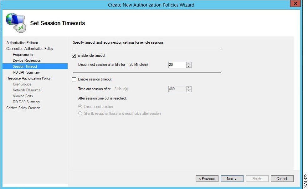
f.![]() The CAP allows the administrator to specify idle timeout and automatic session disconnection. In our example, we have chosen to disconnect if the session has been idle for 20 minutes. Your security policy will dictate the idle timeout and session timeout parameters. After the timeout parameters have been entered, click Next to continue.
The CAP allows the administrator to specify idle timeout and automatic session disconnection. In our example, we have chosen to disconnect if the session has been idle for 20 minutes. Your security policy will dictate the idle timeout and session timeout parameters. After the timeout parameters have been entered, click Next to continue.
Figure 3-24 CAP—Idle and Session Timeouts
g.![]() Once the CAP configuration steps are completed, the administrator can review the entire details of the configuration before submitting the content.
Once the CAP configuration steps are completed, the administrator can review the entire details of the configuration before submitting the content.
Step 2![]() Configure IDMZ RDG Remote Host RAP using the RDG Manager. The RAP will specify what resources the authorized remote users can access in the Industrial Zone.
Configure IDMZ RDG Remote Host RAP using the RDG Manager. The RAP will specify what resources the authorized remote users can access in the Industrial Zone.
a.![]() In Step 1, we completed our CAP configuration. We will now continue the wizard to configure a Resource Authorization Policy. Name the RAP as IDMZ RDG RAP and then click Next.
In Step 1, we completed our CAP configuration. We will now continue the wizard to configure a Resource Authorization Policy. Name the RAP as IDMZ RDG RAP and then click Next.
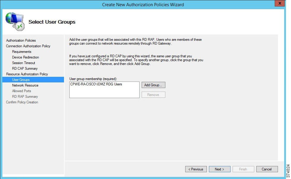
b.![]() The RAP allows the administrator to specify the user groups that can have access to the Industrial Zone resources. We specified the IDMZ RDG Users group in the CAP so the RAP is prepopulated with the same group (see Figure 3-25). This group will be allowed to access the terminal server in the next step. Click Next to continue.
The RAP allows the administrator to specify the user groups that can have access to the Industrial Zone resources. We specified the IDMZ RDG Users group in the CAP so the RAP is prepopulated with the same group (see Figure 3-25). This group will be allowed to access the terminal server in the next step. Click Next to continue.
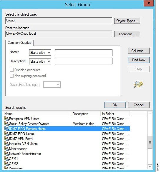
c.![]() The Network Resource page allows the administrator to specify the network resources that the IDMZ RDG Users can access. Previously, we defined a computer group named IDMZ RDG Remote Hosts that included our terminal server TERM01. Click Browse, find and select IDMZ RDG Remote Hosts computer group to add to this RAP (see Figure 3-26 and Figure 3-27).
The Network Resource page allows the administrator to specify the network resources that the IDMZ RDG Users can access. Previously, we defined a computer group named IDMZ RDG Remote Hosts that included our terminal server TERM01. Click Browse, find and select IDMZ RDG Remote Hosts computer group to add to this RAP (see Figure 3-26 and Figure 3-27).
Figure 3-26 RAP—Network Resources
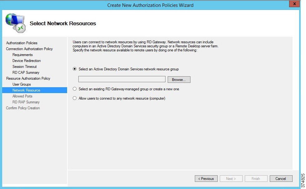
Figure 3-27 RDG Remote Hosts Computer Group
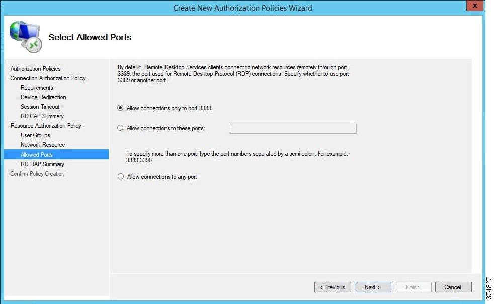
d.![]() By default, the RDG connects to IACS resources on port 3389 (RDP). For this example, we have not changed the default connection port number (see Figure 3-28). If a different port or group of ports is selected, make sure that the firewall rules reflect that. Click Next.
By default, the RDG connects to IACS resources on port 3389 (RDP). For this example, we have not changed the default connection port number (see Figure 3-28). If a different port or group of ports is selected, make sure that the firewall rules reflect that. Click Next.
e.![]() The CAP and RAP configuration is now complete. In Steps 1 and 2, we defined policies for remote access to the terminal server in the Industrial Zone via RD Gateway.
The CAP and RAP configuration is now complete. In Steps 1 and 2, we defined policies for remote access to the terminal server in the Industrial Zone via RD Gateway.
Step 3![]() Configure IACS Remote Host CAP using the RD Gateway Manager. The IACS Remote Host scenario will allow the production administrators and engineers to access the Industrial Zone servers in the IACS Hosts group (Table 19). Configuration of this CAP is similar to Step 1.
Configure IACS Remote Host CAP using the RD Gateway Manager. The IACS Remote Host scenario will allow the production administrators and engineers to access the Industrial Zone servers in the IACS Hosts group (Table 19). Configuration of this CAP is similar to Step 1.
a.![]() Start the wizard to create a new CAP and a RAP. In our example, the CAP will be named RDG IACS Remote Hosts CAP.
Start the wizard to create a new CAP and a RAP. In our example, the CAP will be named RDG IACS Remote Hosts CAP.
b.![]() Select the authentication method (password or smartcard) depending on the security policy.
Select the authentication method (password or smartcard) depending on the security policy.
c.![]() Add user groups that will be associated with this CAP. In our example, Engineers and ProdAdmins groups will be selected.
Add user groups that will be associated with this CAP. In our example, Engineers and ProdAdmins groups will be selected.
Figure 3-29 Remote Host CAP User Groups
d.![]() Configure Device Redirection policy to control access to devices and resources on a client computer in remote desktop sessions. For our example, we will disable device redirection to bolster security.
Configure Device Redirection policy to control access to devices and resources on a client computer in remote desktop sessions. For our example, we will disable device redirection to bolster security.
e.![]() Specify idle and session timeout parameters.
Specify idle and session timeout parameters.
Step 4![]() Configure IACS Remote Host RAP using the RDG Manager after the CAP is created. Configuration of this CAP is similar to Step 2.
Configure IACS Remote Host RAP using the RDG Manager after the CAP is created. Configuration of this CAP is similar to Step 2.
a.![]() Name the policy (RDG IACS Remote Hosts RAP is used in our example).
Name the policy (RDG IACS Remote Hosts RAP is used in our example).
b.![]() Same user groups that we associated in the CAP should be prepopulated in the RAP. In our example, Engineers and ProdAdmins groups will have access to the Industrial Zone resources.
Same user groups that we associated in the CAP should be prepopulated in the RAP. In our example, Engineers and ProdAdmins groups will have access to the Industrial Zone resources.
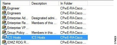
c.![]() Specify the network resources that Engineers and ProdAdmins groups can access. Previously, we defined a computer group named IACS Hosts that included our Industrial Zone servers and computers. This group will be added to the RAP.
Specify the network resources that Engineers and ProdAdmins groups can access. Previously, we defined a computer group named IACS Hosts that included our Industrial Zone servers and computers. This group will be added to the RAP.
Figure 3-30 ICS Hosts Computer Group
d.![]() Accept the default RDP port 3389. This completes the RAP configuration.
Accept the default RDP port 3389. This completes the RAP configuration.
Verifying the RD Gateway Policies
In order to verify the functionality of the RD Gateway, the appropriate SSL certificates must be installed on the computers that will be used in conjunction with the RD Gateway. CPwE IDMZ does not cover PKI in depth nor does it recommend how to properly implement or manage PKI. For test purposes, firewalls and other devices used self-signed certificates as PKI management was beyond the scope of this CPwE DIG.
Configuring Firewall Rules for RD Gateway
The following steps describe the configuration of firewall rules for the Microsoft RD Gateway to allow secure RDP sessions from Enterprise clients to Industrial servers:
Step 1![]() Configure the firewall to allow RDP sessions to traverse the IDMZ via the RD Gateway (see Table 3-13 ).
Configure the firewall to allow RDP sessions to traverse the IDMZ via the RD Gateway (see Table 3-13 ).
|
|
|
|
|
|---|---|---|---|
|
|
|||
|
|
Step 2![]() Configure the firewall to allow RD Gateway to authenticate to the Enterprise DC (see AD configuration section for details). Normally the RD Gateway would be part of the firewall object for IDMZ hosts that authenticate to the DC.
Configure the firewall to allow RD Gateway to authenticate to the Enterprise DC (see AD configuration section for details). Normally the RD Gateway would be part of the firewall object for IDMZ hosts that authenticate to the DC.
ThinManager Remote Desktop Gateway Configuration
Configuring Firewall Rules for ThinManager with RD Gateway
The following steps describe the configuration of firewall rules for the Microsoft RD Gateway to allow secure RDP sessions from Enterprise thin clients to Industrial servers:
Step 1![]() Configure the firewall to allow RDP sessions from thin clients to traverse the IDMZ via the RD Gateway (see Table 3-14 ).
Configure the firewall to allow RDP sessions from thin clients to traverse the IDMZ via the RD Gateway (see Table 3-14 ).
|
|
|
|
|
|---|---|---|---|
|
|
|
|
|
|
Note![]() Table 3-15 citing optional access rules for ThinManager with Remote Desktop Gateway does not have an IDMZ brokered connection and requires direct access through the IDMZ. This may not be acceptable based on risk tolerance and user policies.
Table 3-15 citing optional access rules for ThinManager with Remote Desktop Gateway does not have an IDMZ brokered connection and requires direct access through the IDMZ. This may not be acceptable based on risk tolerance and user policies.
Step 2![]() Configure the firewall to allow RD Gateway to authenticate to the Enterprise DC (see AD configuration section for details). Normally the RD Gateway would be part of the firewall object for IDMZ hosts that authenticate to the DC.
Configure the firewall to allow RD Gateway to authenticate to the Enterprise DC (see AD configuration section for details). Normally the RD Gateway would be part of the firewall object for IDMZ hosts that authenticate to the DC.
ThinManager Configuration for Use with RDG
Access to an RD Gateway is configured in the Display Server and Display Client in ThinManager with the assumption that a device on the industrial or enterprise network might need to access resources across the network security boundary such as the IDMZ. The below sections regarding Remote Desktop Gateway and ThinManager explain how to use the Microsoft RD Gateway with ThinManager and thin clients. These steps assume the following:
Configure the Remote Desktop Server Group
Step 1![]() Create Remote Desktop Server Group by navigating to Display Servers in ThinManager, right clicking on RDS Servers and selecting Add Remote Desktop Server Group.
Create Remote Desktop Server Group by navigating to Display Servers in ThinManager, right clicking on RDS Servers and selecting Add Remote Desktop Server Group.
Figure 3-31 Add Remote Desktop Server Group
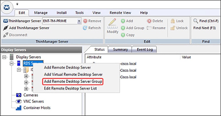
Step 2![]() Enter a name for the Remote Desktop Server Group in the Name field and select the Gateway button to open the RDP Gateway window.
Enter a name for the Remote Desktop Server Group in the Name field and select the Gateway button to open the RDP Gateway window.
Figure 3-32 RDP Gateway Window
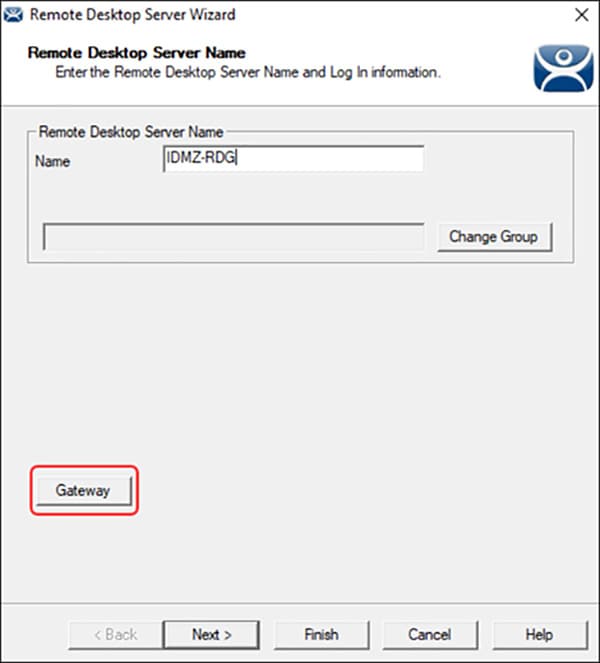
Step 3![]() Enter the Fully Qualified Domain Name (FQDN) of the RD Gateway in the Gateway Name field.
Enter the Fully Qualified Domain Name (FQDN) of the RD Gateway in the Gateway Name field.
Step 4![]() Enter an administrative account and password in the Username and Password fields, if desired. The administrative account should be entered in the User Principal Name (UPN) format.
Enter an administrative account and password in the Username and Password fields, if desired. The administrative account should be entered in the User Principal Name (UPN) format.
- If credentials are provided all the terminals will use those credentials to log into the RD Gateway.
- If left blank the terminal with use the terminal username and password to log into the RD Gateway.
Step 5![]() Select the OK button to accept.
Select the OK button to accept.
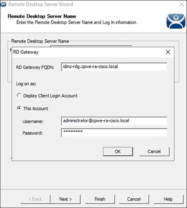
The Remote Desktop Server Group will be empty and will need member servers. These are added from the Remote Desktop Server wizard of each server. Add the Remote Desktop Servers to the Remote Desktop Server Group.
Step 6![]() On the Display Server branch of the ThinManager tree, right click on a RDS Server icon, and select Modify to open the Remote Desktop Server wizard.
On the Display Server branch of the ThinManager tree, right click on a RDS Server icon, and select Modify to open the Remote Desktop Server wizard.
Figure 3-34 Remote Desktop Server Wizard
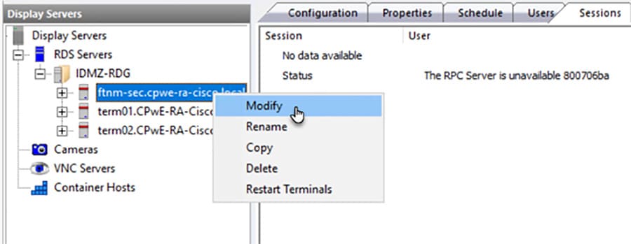
Note![]() Servers will show a red status and the RPC Server error shown above if the optional access rules in Table 3-15 are not configured
Servers will show a red status and the RPC Server error shown above if the optional access rules in Table 3-15 are not configured
Step 7![]() Select the Change Group button to open the Select Parent Remote Desktop Server Group window.
Select the Change Group button to open the Select Parent Remote Desktop Server Group window.
Figure 3-35 Select Parent Remote Desktop Server Group Window
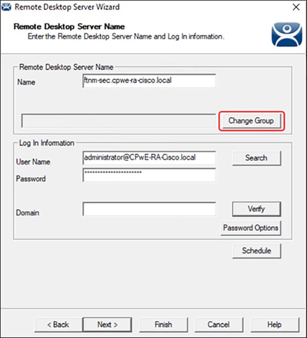
Step 8![]() On the Parent Remote Desktop Server Group window select the Remote Desktop Server Group and select the OK button.
On the Parent Remote Desktop Server Group window select the Remote Desktop Server Group and select the OK button.
Figure 3-36 Select Parent Remote Desktop Server Group
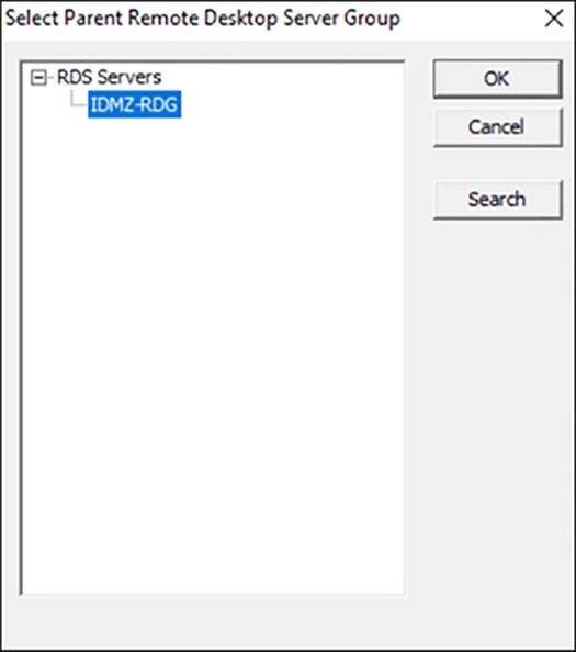
Step 9![]() This will put the Remote Desktop Server into the Remote Desktop Server Group once you select the Finish button to close the wizard. The new status will show in the Group field.
This will put the Remote Desktop Server into the Remote Desktop Server Group once you select the Finish button to close the wizard. The new status will show in the Group field.
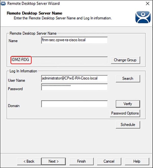
Step 10![]() Once the Remote Desktop Server wizard is closed the ThinManager tree will reflect the changes to the membership in the tree.
Once the Remote Desktop Server wizard is closed the ThinManager tree will reflect the changes to the membership in the tree.
Configure the Display Client
Access to the RD Gateway is assigned in the Display Client wizard:
Step 1![]() Open the Display Client branch of the ThinManager tree, right click on the Remote Desktop Server icon, and select Add Display Client to open the Display Client wizard.
Open the Display Client branch of the ThinManager tree, right click on the Remote Desktop Server icon, and select Add Display Client to open the Display Client wizard.
Figure 3-38 Display Client Wizard
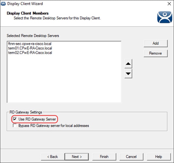
The RD Gateway settings are on the Display Client Members page of the Display Client wizard. Assign the Remote Desktop Servers by selecting the Remote Desktop Server Group. There are two RD Gateway settings:
- Use RD Gateway —This checkbox, if selected, prompts the Display Client to use the Microsoft RD Gateway
- Bypass RD Gateway server for local address —This checkbox, if selected, allows the Display Client to use a Remote Desktop Server without going through the RD Gateway if the terminal and Remote Desktop Server are on the same subnet.
- Leaving both unchecked will create a display client without access to the RD Gateway or the other network or subnet.
Step 2![]() Once the desired RD Gateway Settings have been configured click Finish.
Once the desired RD Gateway Settings have been configured click Finish.
Note For more information on ThinManager configuration see ThinManager Manuals and Guides at:
Configuring Application Security
This section contains guidelines for configuring application security in the CPwE IDMZ, specifically FactoryTalk Security and Microsoft Windows hardening.
FactoryTalk Security Configuration
FactoryTalk Security is not a separate product - it is fully integrated into the FactoryTalk Directory - you will not find it on the Start menu, or in the Add or Remove Programs list in Control Panel.
The FactoryTalk Administration Console is your tool for working with FactoryTalk Security. Using this tool, you can:
- Browse your FactoryTalk system and view the applications, servers, and devices within it
- Create system-wide security settings, and security settings that affect all instances of FactoryTalk-enabled products
- Secure the FactoryTalk Network Directory or FactoryTalk Local Directory
- Secure resources in your FactoryTalk system, including applications and data
- Secure hardware networks and devices
In order to better describe how to configure FactoryTalk Security, we will walk through a scenario and configure FactoryTalk Security to meet the scenario's requirements. In this small example, we will configure the “Deny Privileges” shown in Table 3-16 for users of Studio 5000® software:
|
|
|
|---|---|
|
|
|
|
|
|
|
|
|
|
|
|
|
|
|
|
|
The following section will show how to configure FactoryTalk Security to accomplish these requirements. This example will be configuring a ControlLogix controller named CLX_C.
FactoryTalk Security User Groups Configuration
You can add two different types of user accounts to your FactoryTalk system:
- FactoryTalk User or Group Accounts—These accounts are separate from the user's Microsoft Windows account. This allows you to specify the account’s identity (for example, the user name), set up how the account operates (for example, whether the password expires), and specify the groups the account belongs to.
- Windows-linked User or Group Accounts—These accounts are managed and authenticated by the Windows operating system, but linked into the FactoryTalk Security services. A Windows-linked user account is added to the FactoryTalk system from a Windows domain or workgroup. You cannot change any Windows-linked account information, but you can change the groups the user belongs to. Adding Windows linked accounts to FactoryTalk means you maintain only one identity for users while still having separate Windows and FactoryTalk security parameters.
The Windows-linked user group Windows Administrators account is added to the FactoryTalk Administrators group, giving all Windows Administrators accounts on a local computer full access to the FactoryTalk Network Directory.
Note![]() You can remove the default level of access for Windows Administrators after installation. Typically, different groups are responsible for managing FactoryTalk and Windows security parameters.
You can remove the default level of access for Windows Administrators after installation. Typically, different groups are responsible for managing FactoryTalk and Windows security parameters.
The Windows-linked user group Authenticated Users is added to the FactoryTalk Network Directory and FactoryTalk Local Directory if you install the FactoryTalk Services Platform on a new computer. You can remove this level of access after installation.
In our example, we are going to add the Windows users groups Operators, Engineers, Maintenance, Production Administrators, OEM1 and OEM2 ( Table 3-12 ).
Step 1![]() Add Windows-linked users groups to the FactoryTalk Network Directory.
Add Windows-linked users groups to the FactoryTalk Network Directory.
a.![]() Open the FactoryTalk Administration Console: Start > All Programs > Rockwell Software > FactoryTalk Administration Console and then log on to the FactoryTalk Network Directory.
Open the FactoryTalk Administration Console: Start > All Programs > Rockwell Software > FactoryTalk Administration Console and then log on to the FactoryTalk Network Directory.
b.![]() Right-click User Groups and select Windows Linked User Group (see Figure 3-39).
Right-click User Groups and select Windows Linked User Group (see Figure 3-39).
Figure 3-39 FactoryTalk Administration Console—Add User Group
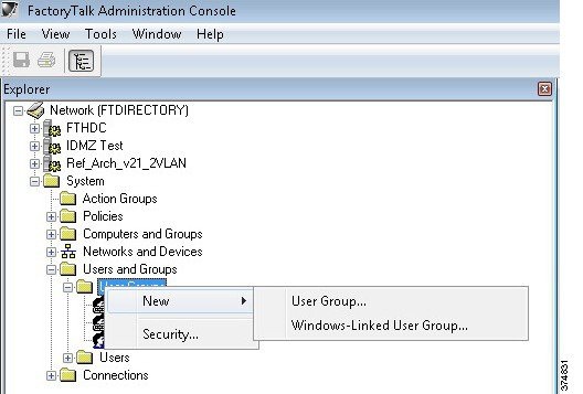
c.![]() In the New Windows Linked User Group dialog box, click Add > Locations > Entire Directory > OK. The Select Groups dialog box will reappear with the From this location field changed from the local computer name to the entire directory (see Figure 3-40).
In the New Windows Linked User Group dialog box, click Add > Locations > Entire Directory > OK. The Select Groups dialog box will reappear with the From this location field changed from the local computer name to the entire directory (see Figure 3-40).
Figure 3-40 Select Groups—Location
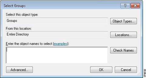
d.![]() Click Advanced > Find Now to search all of the User Group within the domain. Select Engineers, Maintenance, Operators, OEM1, OEM2 and ProdAdmins groups (see Figure 3-41). Click OK.
Click Advanced > Find Now to search all of the User Group within the domain. Select Engineers, Maintenance, Operators, OEM1, OEM2 and ProdAdmins groups (see Figure 3-41). Click OK.
Figure 3-41 Select Groups—Advanced
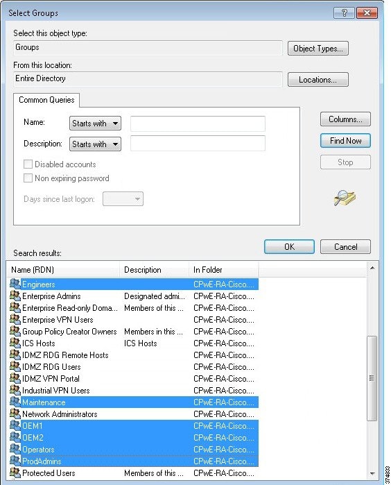
e.![]() Verify that the correct groups were added and click OK. The FactoryTalk New Windows-Linked User Group dialog box will show the domain users that are to be added. Click OK to complete the configuration.
Verify that the correct groups were added and click OK. The FactoryTalk New Windows-Linked User Group dialog box will show the domain users that are to be added. Click OK to complete the configuration.
f.![]() Once the user groups are added, you will see them listed under the User Groups folder in the FactoryTalk Administration Console.
Once the user groups are added, you will see them listed under the User Groups folder in the FactoryTalk Administration Console.
Figure 3-42 FactoryTalk Administration Console—User Groups Created
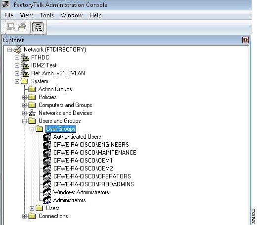
Studio 5000 Product Policies Configuration
FactoryTalk Security allows the security administrator fine granularity of actions that can be secured for Studio 5000, FactoryTalk View SE and other Rockwell Automation products. In our example, we will start by configuring the Studio 5000 product policies, in particular who can secure and unsecure a controller.
- A policy is a setting that applies across the entire FactoryTalk IACS system. For example, all FactoryTalk products that share a single FactoryTalk Directory use the same audit policy setting that records a user's failure to access a secured object or feature because the user has insufficient security permissions. If you disable this policy, none of the FactoryTalk products in your system will record failed attempts to access secured objects or features.
- A product policy secures either a system-wide feature or system-wide configuration data that is specific to a particular product. Each FactoryTalk product provides its own set of product-specific policies, which means that the product policies available on your system vary, depending on which FactoryTalk products you have installed.
Step 1![]() Configure Studio 5000 policies to align with the User Groups requirements in Table 3-12.
Configure Studio 5000 policies to align with the User Groups requirements in Table 3-12.
a.![]() Under System > Policies > Product Policies, right-click RSLogix 5000 and select Configure Feature Security (see Figure 3-43).
Under System > Policies > Product Policies, right-click RSLogix 5000 and select Configure Feature Security (see Figure 3-43).
Figure 3-43 FactoryTalk Administration Console—Product Policies
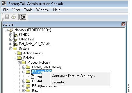
b.![]() First we need to add the User Groups and then assign permissions. On the Feature Security dialog box, select Add to display the list of available user groups. Remember that we have added Windows-linked users in a previous step so they will be included in the list of users. Select PRODADMINS and click OK (see Figure 3-44).
First we need to add the User Groups and then assign permissions. On the Feature Security dialog box, select Add to display the list of available user groups. Remember that we have added Windows-linked users in a previous step so they will be included in the list of users. Select PRODADMINS and click OK (see Figure 3-44).
Figure 3-44 Feature Security—Select User Group
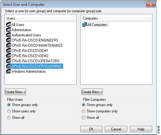
c.![]() The PRODADMINS group is now added to the user list in the Feature Security dialog box. We will now assign Studio 5000 product policy permissions to this group. We want to allow the Production Administrators unrestricted security access, so we select Allow on all Studio 5000 actions (see Figure 3-45).
The PRODADMINS group is now added to the user list in the Feature Security dialog box. We will now assign Studio 5000 product policy permissions to this group. We want to allow the Production Administrators unrestricted security access, so we select Allow on all Studio 5000 actions (see Figure 3-45).
Figure 3-45 Feature Security—Allow All
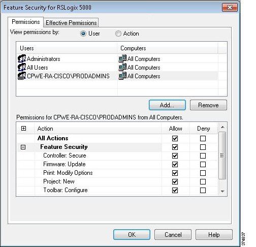
d.![]() Repeat the same step for each user group according to Table 3-12. In our example, the Maintenance group should not be allowed to update the firmware. We can select Deny for Firmware: Update action to achieve this requirement.
Repeat the same step for each user group according to Table 3-12. In our example, the Maintenance group should not be allowed to update the firmware. We can select Deny for Firmware: Update action to achieve this requirement.
e.![]() We also wanted to stricter control over the OEM1 and OEM2 group. We can simply select Deny for additional actions to meet our requirements (see Figure 3-46).
We also wanted to stricter control over the OEM1 and OEM2 group. We can simply select Deny for additional actions to meet our requirements (see Figure 3-46).
Figure 3-46 Feature Security—Deny
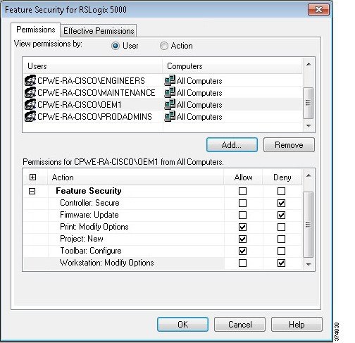
f.![]() Once permissions for all groups have been configured and applied, a Security Settings warning dialog will appear. It reminds that Deny entries take precedence over Allow entries if a user is a member of two groups.
Once permissions for all groups have been configured and applied, a Security Settings warning dialog will appear. It reminds that Deny entries take precedence over Allow entries if a user is a member of two groups.
Controller Security Configuration
Now that we have created FactoryTalk user groups and assigned Studio 5000 product policies, it is time to set the granular security permissions for each group specific to a controller. Actions such as Tag: Force or Tag: Create can be secured through FactoryTalk Security.
Step 1![]() Add a logical name to the controller. It is recommended that security settings be applied to the controller's logical name. The logical name is the same as the name shown on the controller properties dialog. Security settings for a logical name apply to the offline project as well as when the project is downloaded to the controller.
Add a logical name to the controller. It is recommended that security settings be applied to the controller's logical name. The logical name is the same as the name shown on the controller properties dialog. Security settings for a logical name apply to the offline project as well as when the project is downloaded to the controller.
a.![]() To set the logical name in the FactoryTalk Administration Console, expand the Networks and Devices topology and navigate to the controller. In our example, the controller is named CLX_C. Right-click the controller and select Properties.
To set the logical name in the FactoryTalk Administration Console, expand the Networks and Devices topology and navigate to the controller. In our example, the controller is named CLX_C. Right-click the controller and select Properties.
b.![]() Select the Logical name that coincides with your controller's name. If the name does not appear in the Networks and Devices tree, you need to manually update the path information for the controller.
Select the Logical name that coincides with your controller's name. If the name does not appear in the Networks and Devices tree, you need to manually update the path information for the controller.
Figure 3-47 Controller Properties—Logical Name
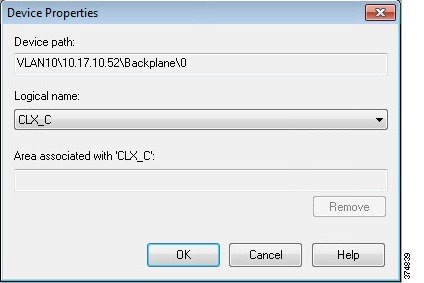
Step 2![]() Assign Studio 5000 permissions to the controller based on the user group. In our example, we will assign all Studio 5000 permissions on the CLX_C controller to the Production Administrators group (PRODADMIN) while setting a Deny permission to the Tag: Force to the OEM1 group.
Assign Studio 5000 permissions to the controller based on the user group. In our example, we will assign all Studio 5000 permissions on the CLX_C controller to the Production Administrators group (PRODADMIN) while setting a Deny permission to the Tag: Force to the OEM1 group.
a.![]() Select the controller in the Network and Devices branch of the FactoryTalk Administration console. In our example, this is CLX_C. Right-click and select Security.
Select the controller in the Network and Devices branch of the FactoryTalk Administration console. In our example, this is CLX_C. Right-click and select Security.
b.![]() The Security Settings screen allows the security administrator to add users and user groups and assign permissions to each. Click Add to find and select the Production Administrators (PRODADMINS) user group.
The Security Settings screen allows the security administrator to add users and user groups and assign permissions to each. Click Add to find and select the Production Administrators (PRODADMINS) user group.
c.![]() The Security Settings screen will now show the PRODADMINS group. We want to allow all actions to the CLX_C controller for this group so select Allow in the All Actions row (see Figure 3-48).
The Security Settings screen will now show the PRODADMINS group. We want to allow all actions to the CLX_C controller for this group so select Allow in the All Actions row (see Figure 3-48).
Figure 3-48 Controller Permissions—Allow All
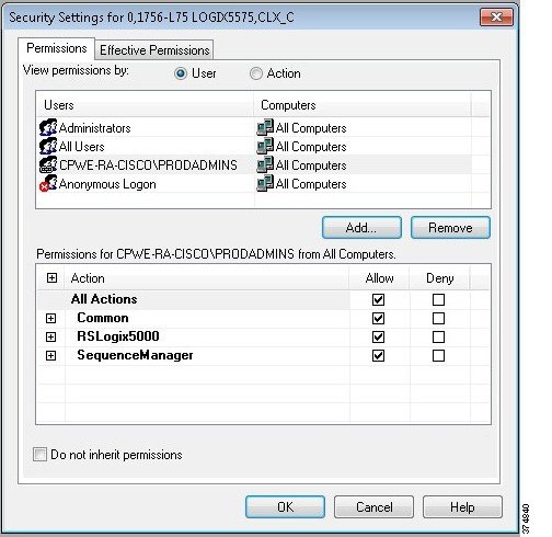
d.![]() Now we will deny the Tag: Force permission for the OEM1 group. From the Security Settings screen, click Add and select the OEM1 group to add to the configuration list. Expand the RSLogix 5000 permission set and select Deny for the Tag: Force action (see Figure 3-49).
Now we will deny the Tag: Force permission for the OEM1 group. From the Security Settings screen, click Add and select the OEM1 group to add to the configuration list. Expand the RSLogix 5000 permission set and select Deny for the Tag: Force action (see Figure 3-49).
Figure 3-49 Controller Permissions—Deny
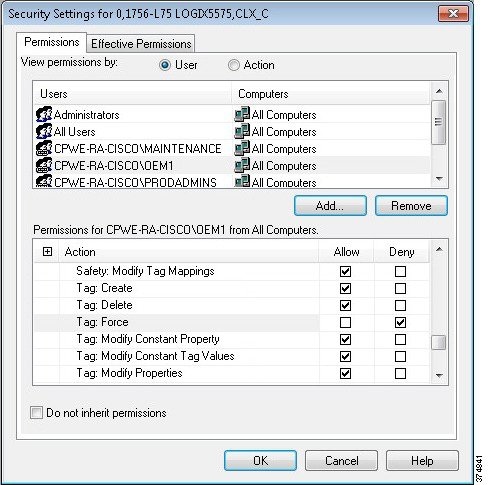
Step 3![]() Verify effective permissions for the groups. FactoryTalk Security is very flexible and allows users and user groups to inherit security permissions. Because of this flexibility, tools exist to check the effective permission for each user, user group and device. In this step, we will check the effective permissions of the OEM1 group to verify they are not allowed to “Tag: Force” on the CLX_C controller.
Verify effective permissions for the groups. FactoryTalk Security is very flexible and allows users and user groups to inherit security permissions. Because of this flexibility, tools exist to check the effective permission for each user, user group and device. In this step, we will check the effective permissions of the OEM1 group to verify they are not allowed to “Tag: Force” on the CLX_C controller.
a.![]() Select the controller in the Network and Devices branch of the FactoryTalk Administration console. Right-click and select Security.
Select the controller in the Network and Devices branch of the FactoryTalk Administration console. Right-click and select Security.
b.![]() Once the Security Settings dialog box opens, select the Effective Permissions tab. Browse to the desired user group (in our example, OEM1). The Effective Permissions will be shown for the OEM1 group. In our example, we see that Tag: Force action is not allowed (see Figure 3-50).
Once the Security Settings dialog box opens, select the Effective Permissions tab. Browse to the desired user group (in our example, OEM1). The Effective Permissions will be shown for the OEM1 group. In our example, we see that Tag: Force action is not allowed (see Figure 3-50).
Figure 3-50 Controller Security—Effective Permissions
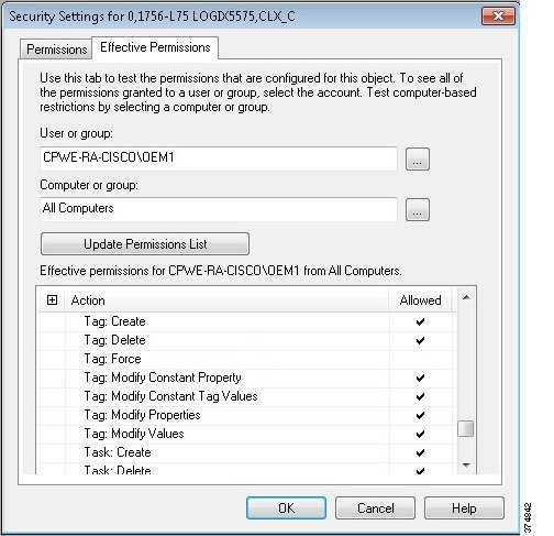
Step 4![]() Apply FactoryTalk Security to the controller in Studio 5000.
Apply FactoryTalk Security to the controller in Studio 5000.
a.![]() Open the CLX_C project with Studio 5000. Right-click the Controller folder and select Properties. Within the Controller Properties screen, select the Security tab. You will notice that the Security Authority will be set to No Protection (see Figure 3-51).
Open the CLX_C project with Studio 5000. Right-click the Controller folder and select Properties. Within the Controller Properties screen, select the Security tab. You will notice that the Security Authority will be set to No Protection (see Figure 3-51).
Figure 3-51 Controller Properties—No Protection
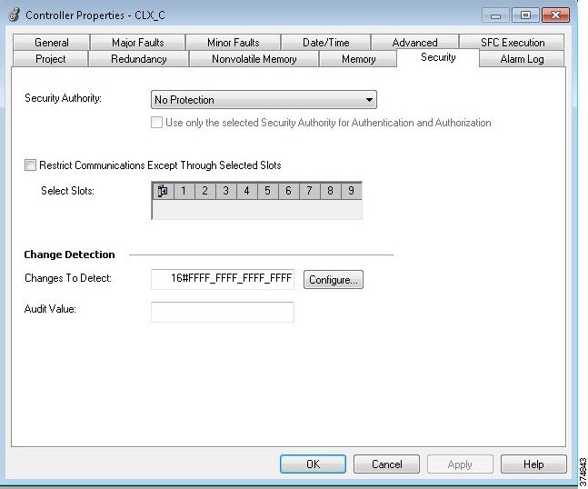
b.![]() Change the Security Authority option to FactoryTalk Security (see Figure 3-52) and click OK. The Logix Designer warning dialog box is displayed. Select Yes to secure the controller.
Change the Security Authority option to FactoryTalk Security (see Figure 3-52) and click OK. The Logix Designer warning dialog box is displayed. Select Yes to secure the controller.
Figure 3-52 Controller Properties—FactoryTalk Security
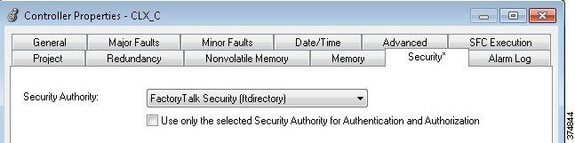
Step 5![]() Test the FactoryTalk Security configuration on the controller.
Test the FactoryTalk Security configuration on the controller.
a.![]() Log onto FactoryTalk Security as a Production Administrator. In the Studio 5000, when online with the controller. Right-click the tag. The Force On and Force Off actions are available for a tag (see Figure 3-53).
Log onto FactoryTalk Security as a Production Administrator. In the Studio 5000, when online with the controller. Right-click the tag. The Force On and Force Off actions are available for a tag (see Figure 3-53).
Figure 3-53 Force Tag Actions Available
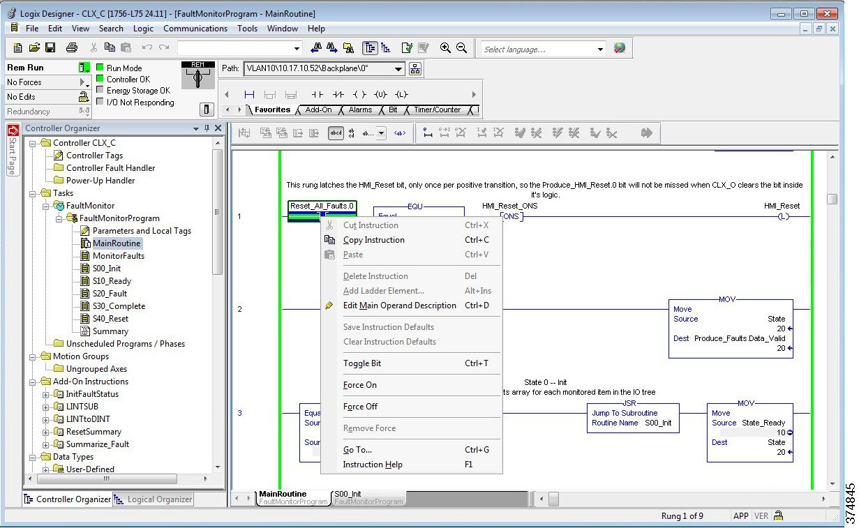
Step 6![]() Log onto FactoryTalk Security as an OEM1. The Force On and Force Off actions are now disabled (see Figure 3-54).
Log onto FactoryTalk Security as an OEM1. The Force On and Force Off actions are now disabled (see Figure 3-54).
Figure 3-54 Force Tag Actions Disabled
OS Hardening Configuration
This section provides a high-level overview of OS hardening configuration steps using Microsoft technologies outlined in Operating System Hardening.
Microsoft AppLocker Configuration
AppLocker uses the Application Identity service (AppIDSvc) for rule enforcement. For AppLocker rules to be enforced, this service must be set to start automatically in the Group Policy Object (GPO).
While the configuration options are unique to each customer and application, Rockwell Automation has provided a sample policy you can use as a guideline to help assist you to get started.
Note This sample policy can be downloaded from the following Knowledgebase article:
For more information about AppLocker rules, see:
Note![]() Before continuing, it is suggested to use audit-only mode to deploy the policy and understand its impact before enforcing it and rolling it out to a production environment.
Before continuing, it is suggested to use audit-only mode to deploy the policy and understand its impact before enforcing it and rolling it out to a production environment.
Step 1![]() Import the Rockwell Automation example policy.
Import the Rockwell Automation example policy.
a.![]() Open the Local Group Policy Editor by going to Start > Run and entering gpedit.msc.
Open the Local Group Policy Editor by going to Start > Run and entering gpedit.msc.
b.![]() Navigate to Application Control Policies > AppLocker. Right-click AppLocker and select Import Policy (see Figure 3-55).
Navigate to Application Control Policies > AppLocker. Right-click AppLocker and select Import Policy (see Figure 3-55).
Figure 3-55 Group Policy Editor—Import AppLocker Example Policy
c.![]() Navigate to the place where you downloaded the AppLocker_RAUser.xml file and import it. This will replace any existing policies with the example one.
Navigate to the place where you downloaded the AppLocker_RAUser.xml file and import it. This will replace any existing policies with the example one.
d.![]() Now within the AppLocker policy, rules can be observed and used to expand upon (see Figure 3-56).
Now within the AppLocker policy, rules can be observed and used to expand upon (see Figure 3-56).
Figure 3-56 Group Policy Editor—AppLocker Policy Details
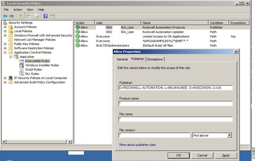
Cisco Telemetry Broker Configuration
The following example will present a scenario and show the configuration steps to traverse network data across the IDMZ using the Cisco Telemetry Broker. It is assumed that the user has the necessary knowledge to configure network devices to send netflow and/or syslog to a given IP address.
Note For details on the configuration of the Cisco Telemetry Broker, refer to Cisco Telemetry Broker Virtual Appliance Deployment and Configuration Guide at:
- https://www.cisco.com/c/dam/en/us/td/docs/security/Telemetry_Broker/Deployment/TB_1_1_Virtual_Appliance_Deployment_and_Configuration_Guide_DV_3_0.pdf
Installing the Virtual Appliances
In our scenario, both the Manager node and Broker node were installed on the ESXI platform. For other supported platforms, see the guide linked above.
Step 1![]() Install the Manager Node:
Install the Manager Node:
a.![]() Download the Manager Node OVA file.
Download the Manager Node OVA file.
b.![]() Log in to the VMWare vSphere web user interface console.
Log in to the VMWare vSphere web user interface console.
c.![]() From the side menu, right-click Virtual Machine and then choose Create/Register VM.
From the side menu, right-click Virtual Machine and then choose Create/Register VM.
d.![]() Choose Deploy a virtual machine from an OVF or OVA file.
Choose Deploy a virtual machine from an OVF or OVA file.
e.![]() Enter the name of the OVA file.
Enter the name of the OVA file.
f.![]() Configure the settings as shown in Figure 3-57.
Configure the settings as shown in Figure 3-57.
Figure 3-57 ESKI Deployment Options
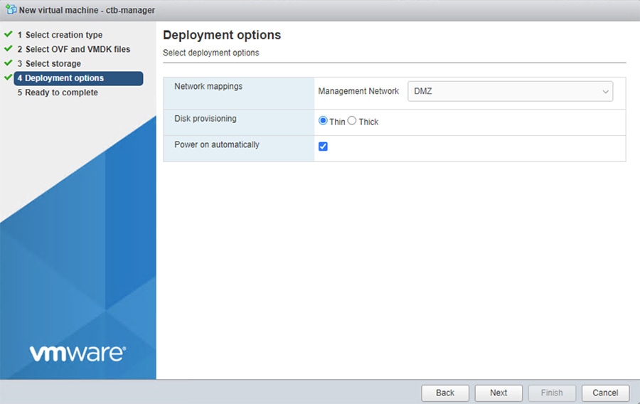
From the manager node virtual machine within the vmware user interface, open a web console and log in to the virtual machine (the username is install; there is no password).
Figure 3-58 CTB Manager Node CLI
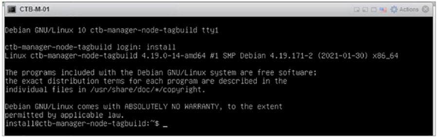
Step 2![]() Run the sudo ctb-install command.
Run the sudo ctb-install command.
Enter the following information:
–![]() Contain at least 8 characters
Contain at least 8 characters
–![]() Contain at least 1 lowercase letter
Contain at least 1 lowercase letter
–![]() Contain at least 1 uppercase letter
Contain at least 1 uppercase letter
–![]() Contains at least 1 of these special characters: @ # $ % ^ & * ! + ?
Contains at least 1 of these special characters: @ # $ % ^ & * ! + ?
–![]() Cannot be a commonly used phrase or sequence
Cannot be a commonly used phrase or sequence
–![]() Cannot resemble any identifying attributes of the user (such as the username)
Cannot resemble any identifying attributes of the user (such as the username)
–![]() IPv4 address, subnet mask, and default gateway address for the Management Network interface
IPv4 address, subnet mask, and default gateway address for the Management Network interface
If this is the first time you are logging in to the manager web interface, you must first create the first Superuser account before you install any broker nodes. We suggest assigning the username of webadmin so as not to confuse it with the admin user.
h.![]() In a web browser, navigate to the following site to create it: https://<manager_ip_address>
In a web browser, navigate to the following site to create it: https://<manager_ip_address>
Step 3![]() Install the Broker Node:
Install the Broker Node:
a.![]() Download the Broker Node OVA file.
Download the Broker Node OVA file.
b.![]() Log in to the VMWare vSphere web user interface console.
Log in to the VMWare vSphere web user interface console.
c.![]() From the side menu, right-click Virtual Machine and then choose Create/Register VM.
From the side menu, right-click Virtual Machine and then choose Create/Register VM.
d.![]() Choose Deploy a virtual machine from an OVF or OVA file.
Choose Deploy a virtual machine from an OVF or OVA file.
e.![]() Enter the name of the OVA file.
Enter the name of the OVA file.
f.![]() Configure the settings as shown in Figure 3-59. Note: Deployment type will differ depending on network. For more information see Cisco Telemetry Broker.
Configure the settings as shown in Figure 3-59. Note: Deployment type will differ depending on network. For more information see Cisco Telemetry Broker.
Figure 3-59 ESXI Deployment Options
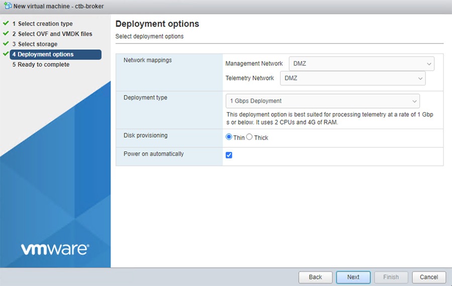
h.![]() From the manager node virtual machine within the vmware user interface, open a web console and log in to the virtual machine (the username is install; there is no password).
From the manager node virtual machine within the vmware user interface, open a web console and log in to the virtual machine (the username is install; there is no password).
Figure 3-60 CTB Broker Node CLI
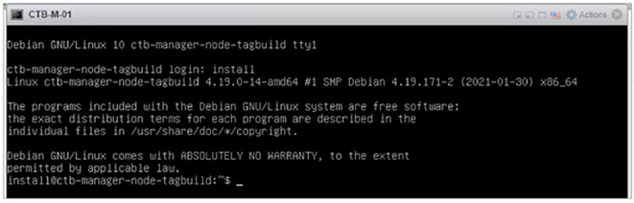
i.![]() Run the sudo ctb-install command.
Run the sudo ctb-install command.
Enter the following information:
–![]() Contain at least 8 characters
Contain at least 8 characters
–![]() Contain at least 1 lowercase letter
Contain at least 1 lowercase letter
–![]() Contain at least 1 uppercase letter
Contain at least 1 uppercase letter
–![]() Contains at least 1 of these special characters: @ # $ % ^ & * ! + ?
Contains at least 1 of these special characters: @ # $ % ^ & * ! + ?
–![]() Cannot be a commonly used phrase or sequence
Cannot be a commonly used phrase or sequence
–![]() Cannot resemble any identifying attributes of the user (such as the username)
Cannot resemble any identifying attributes of the user (such as the username)
–![]() IPv4 address, subnet mask, and default gateway address for the Management Network interface
IPv4 address, subnet mask, and default gateway address for the Management Network interface
j.![]() Run the sudo ctb-manage command.
Run the sudo ctb-manage command.
Enter the following information:
–![]() IP address of the manager node
IP address of the manager node
–![]() Username of the super user account you create in the manager node
Username of the super user account you create in the manager node
–![]() Password of the super user account you create in the manager node
Password of the super user account you create in the manager node
Step 4![]() Add the Broker node to the Manager Node.
Add the Broker node to the Manager Node.
In Cisco Telemetry Broker, click Broker Nodes from the main menu:
a.![]() In the Broker Nodes table, click the applicable broker node.
In the Broker Nodes table, click the applicable broker node.
b.![]() In the Telemetry Interface section, click the Edit icon.
In the Telemetry Interface section, click the Edit icon.
c.![]() Configure the IP AddressPrefixLen, and Gateway address.
Configure the IP AddressPrefixLen, and Gateway address.
e.![]() Click Destinations from the main menu.
Click Destinations from the main menu.
f.![]() In the upper right corner of the page, click + Add Destination.
In the upper right corner of the page, click + Add Destination.
h.![]() Enter a Destination IP Address and Destination UDP Port for this destination.
Enter a Destination IP Address and Destination UDP Port for this destination.
i.![]() Enable Check destination availability if you want to establish an inactivity interval between the manager node and the destination. This allows you to identify when a destination is nonresponsive or not receiving telemetry.
Enable Check destination availability if you want to establish an inactivity interval between the manager node and the destination. This allows you to identify when a destination is nonresponsive or not receiving telemetry.
Figure 3-61 Add Destination for Data Forwarding
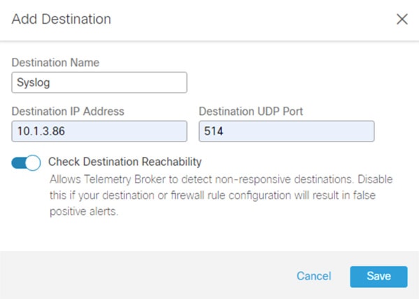
Step 5![]() Create a forwarding rule in Cisco Telemetry Broker.
Create a forwarding rule in Cisco Telemetry Broker.
Note![]() You must add at least one rule to the destination before it will receive telemetry.
You must add at least one rule to the destination before it will receive telemetry.
a.![]() In Cisco Telemetry Broker, click Destinations from the main menu.
In Cisco Telemetry Broker, click Destinations from the main menu.
b.![]() In the lower left corner of the applicable destination summary, click + Add rule.
In the lower left corner of the applicable destination summary, click + Add rule.
c.![]() Enter a Receiving UDP Port.
Enter a Receiving UDP Port.
d.![]() If you want to specify subnets over which this destination will receive certain traffic, add one or more Subnets.
If you want to specify subnets over which this destination will receive certain traffic, add one or more Subnets.
Figure 3-62 Configure Rule in CTB
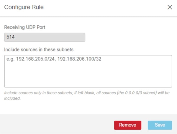
Configuring Firewall Rules for Cisco Telemetry Broker
The following steps describe the configuration of firewall rules for the Cisco Telemetry Broker to allow Industrial Clients to send UDP data outside of the network. Although the Cisco Telemetry Broker supports any UDP message, the tests done in this lab was for Netflow and Syslog message traversal.
Step 1![]() Configure the firewall to allow telemetry to traverse the IDMZ via the Cisco Telemetry Broker (see Table 3-17 ).
Configure the firewall to allow telemetry to traverse the IDMZ via the Cisco Telemetry Broker (see Table 3-17 ).
|
|
|
|
|
 Feedback