Solution Architecture
This chapter, which describes the end-to-end system architecture for Release 2.0 of the DRaaS Solution, includes the following major topics:
Solution High Level Architecture
The DRaaS Solution enables CSPs to offer disaster recovery services to customers to protect their physical and virtual servers. These service offerings are enabled when a CSP deploys the VMDC VSA 1.0-based infrastructure and then overlays one of the DR solutions from Cisco's partners, InMage or Zerto. See Figure 2-1.
VMDC VSA 1.0 is the first VMDC release dealing specifically with the transition to Network Function Virtualization (NFV) of IaaS network services in the data center. Such services comprise virtual routers, virtual firewalls, load balancers, network analysis and WAN optimization virtual appliances.
The DRaaS Solution addresses the following design principles and architectural goals:
- Secure multi-tenancy
- Secure, modular, and highly available cloud
- Continuous data protection (CDP)
- Physical-to-Virtual (P2V) and Virtual-to-Virtual (V2V) Disaster Recovery
- Near zero RPO and RTO-capable DRaaS
- Automated runbook automation
- Self-service multi-tenant portal
Figure 2-1 DRaaS High Level Architecture
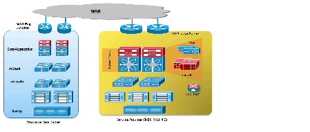
The physical system architecture consists of the building blocks described in the following sections.
Cloud Service Provider
This DRaaS system will utilize VMDC-based provider clouds, so that failed over workloads can be securely placed into their tenant containers.
The provider cloud within the DRaaS system is based on VMDC VSA 1.0, which is the first system release dealing specifically with the transition to virtualized L4-7 services. In this release, the main focus is on Public Provider use cases, building a new logical topology model around the creation of VPC tenant containers within the shared data center infrastructure, using eBGP for dynamic routing between a centralized data center edge PE and unique per-tenant virtual customer edge (CE) routers within the data center.
The VMDC VSA 1.0 architecture works with Vblock, FlexPod, or any other integration stack. Integrated stacks can be added as required to scale the SP cloud environment. Based on the customer's production environment and needs, a specific tenancy model can be selected to provide similar services in the cloud-matching production environment. VMDC architecture and deployment models will be covered in detail in this chapter.
Enterprise Data Center
The disaster recovery solutions should address enterprise customer requirements for various vertical industries and geographies. The enterprise data center design is therefore expected to vary from customer to customer. The intent of the DRaaS Solution is to keep the enterprise data center architecture generic to provide the greatest coverage. While the data center architecture is almost irrelevant and the solution supports heterogeneous replication across any-to-any infrastructure, a typical three tier (core/aggregation and access) data center architecture is suggested in the solution.
WAN Connectivity
The WAN connectivity design principles provided by VMDC are maintained and supported. The VMDC solution allows for multiple connectivity mechanisms for tenants and end-users to connect to their cloud resources. Some of these mechanisms include:
- Layer 3 connectivity
- L3VPN (MPLS)-based, where the tenant sites connect to the cloud data center through MPLS-VPN services
- IP (Internet)-based, where clients access cloud resources directly from the Internet
- Layer 2 connectivity
- Layer 2 (VLAN-extension)-based, where the tenant sites connect to the cloud data center through L2VPN services like Virtual Private LAN Service (VPLS) and Ethernet over MPLS (EoMPLS)
Similarly, the VMDC solution allows for multiple forms of Layer 2 Extension or Data Center Interconnect (DCI) for interconnecting provider data centers or connecting Enterprise data centers to provider data centers. Some of these mechanisms include:
- IP-based mechanisms for Layer 2 extension - OTV
- MPLS-based mechanisms for Layer 2 extension—e.g., VPLS, H-VPLS, and EoMPLS
The DRaaS solution will also support any of these interconnect mechanisms for connecting enterprise data center to the VMDC-based provider cloud.
This phase of the DRaaS solution supports partial failover of customer's environment. Partial failover will be provided in two ways:
- By utilizing a per-tenant CSR1000V instantiated in the enterprise data center
- Providing OTV-based Layer 2 interconnectivity from the enterprise data center to the tenants’ VPC in the VMDC-based provider cloud.
CSR 1000V will also provide IPSec-based traffic encryption between the primary and secondary sites. Per-tenant CSR1000V will also provide Layer 2 extension and IP Path optimization between two VPCs within the VMDC-based provider cloud for IaaS (In-Cloud workloads) disaster recovery.
Hot Standby Compute Resources
In the provider networks, UCS Service Profile Templates can be leveraged to provide compute resources on an as-needed basis to avoid large CAPEX investments. The CSP can build an infrastructure with fewer than one-to-one compute resources for all the customer servers being protected. UCS compute resources can be easily and quickly deployed using UCS Director when a disaster event is declared. Once the compute resources boot up, they can be used to host recovery virtual or physical machines.
Partner Solution for Providing Disaster Recovery
Data replication and recovery of the production servers will be provided by InMage ScoutCloud or Zerto Virtual Replication solutions. InMage is a host-based solution with agents installed on each of the servers that require protection, while Zerto is a hypervisor-based solution where virtual machines can be protected at the hypervisor layer. While their approach and supported features are different, both solutions provide a basic set of capabilities to the CSP:
Solution Logical Topology
Using the building blocks described above, a logical topology of the DRaaS solution can be created as shown in Figure 2-2 and Figure 2-3. Each customer will have a dedicated network container created on the CSP VMDC cloud. The network containers will be created based on the necessary security and network services required by the enterprise customers.
Any network topology on the customer's data center can be matched on the VMDC cloud using network containers. Predefined containers provide examples for different types of deployments. Automated provisioning and management logic for each customer type is pre-defined in the management and orchestration software. Customers can choose from existing models or define their own customized models.
With the deployment of lightweight components and utilizing the network security provided by VMDC architecture, customers can replicate their data into a secure cloud environment for recovery.
Data changes are collected from the production servers as they occur, directly in memory before they are written to disk, and sent to a software appliance within an enterprise data center or at the hypervisor layer by a virtual appliance. Because of this approach, absolutely no additional I/O load is created on production servers due to replication.
The solution provides CDP for the customer's production servers. The customers will be able to recover their environments to any point in time before the disaster occurred. The servers are protected from the physical disasters and from logical disasters due to CDP.
Application consistency is enforced at regular intervals through VSS integration on Windows and native application-specific mechanisms on Linux and Solaris systems. Application consistency is also enforced at the guest level in virtual environments such as VMware ESX, Xen Server, and Hyper-V. These application-consistent points are tagged by a bookmark and archived as part of the CDP data. They can be leveraged to perform application consistent recoveries within stringent recovery time objectives.
For DRaaS to the Cloud customers, the production workloads from each enterprise data center will be replicated to the corresponding network container on the VMDC cloud and will be available for recovery purposes. The customer's network will be extended across the WAN connection using OTV between CSR 1000V routers at each site.
For ICDR customers, all or part of the production workloads for each enterprise will reside in the corresponding network container on the VMDC cloud; the replication necessary to protect these servers will go to a second CSP site. Again, the customer's network will be extended across the WAN connection using OTV between CSR 1000V routers. To connect the customer containers between the two CSP sites, another OTV link between CSR 1000Vs will be deployed, but with LISP added to provide IP mobility and path optimization between CSP sites.
Figure 2-2 DRaaS Logical Topology
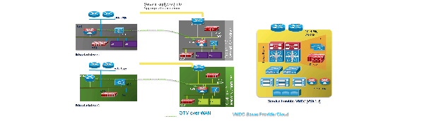
Figure 2-3 In-Cloud Disaster Recovery Logical Topology

VMDC Architecture for Cloud
The VMDC system is the Cisco reference architecture for IaaS cloud deployments. This Cisco cloud architecture is designed around a set of modular data center components consisting of building blocks of resources called PODs, or Points of Delivery. These PODs comprise the Cisco UCS, SAN and NAS storage arrays, access (switching) layers, aggregation (switching and routing) layers connecting into the DSN-based services layer or connecting directly to physical service appliances or virtual service appliances hosted on the UCS systems, and multiple 10 GE fabric using highly scalable Cisco network switches and routers.
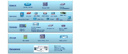
The VMDC system is built around the UCS, Nexus 1000V, Nexus 5000/6000 and Nexus 7000 switches, Multilayer Director Switch (MDS), ASR 1000, ASR 9000, ASA 5585-X or Adaptive Security Appliance Services Module (ASASM), Catalyst 6500 DSN, Citrix SDX, Nexus 1000V, CSR 1000V, ASA 1000V, Citrix NetScaler VPX, VSG, VMware vSphere, EMC VMAX, VNX, and NetApp FAS storage arrays. BMC Cloud Lifecycle Manager (CLM) suite and Cisco Intelligent Automation for Cloud (IAC) suite provide the cloud service orchestration. Figure 2-4 provides a synopsis of the functional infrastructure components comprising the VMDC system.
Figure 2-4 VMDC Functional Components
VMDC Modular Components
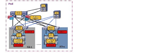
The VMDC system architecture provides a scalable solution that can address the needs of Enterprise and service provider cloud data centers. This architecture enables customers to select the design that best suits their immediate needs while providing a solution that can scale to meet future needs without retooling or redesigning the data center. This scalability is achieved using a hierarchical design with two different modular building blocks, POD and ICS stack.
Point of Delivery (POD)
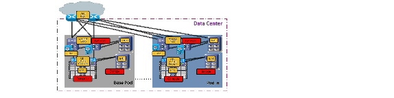
The modular data center design starts with a basic infrastructure module called a POD. A POD is a repeatable, physical construct with predictable infrastructure characteristics and deterministic functions. It identifies a modular unit of data center components and enables customers to add network, compute, and storage resources incrementally. This modular architecture provides a predictable set of resource characteristics (network, compute, and storage resource pools, power and space consumption) per unit that are added repeatedly as needed.
In this design, the aggregation layer switch pair, services layer nodes, and one or more integrated compute stacks are contained within a POD. The POD connects to the WAN/PE layer device in the data center, in the VMDC VSA 1.0 and VMDC 2.3 architectures; and connects to the core layer in previous VMDC 2.2 and 2.0 architectures. To scale a POD, providers can add additional integrated compute stacks and continue to scale in this manner until the POD resources are exceeded. To scale the data center, additional PODs can be deployed and connected to the core layer devices. Figure 2-5 illustrates how PODs can be used to scale compute, network, and storage in predictable increments within the data center.
Figure 2-5 PODs for Scaling the Data Center
ICS Stack
The second modular building block utilized is a generic ICS stack based on existing models, such as the VCE Vblock or Cisco/NetApp FlexPod infrastructure packages. The VMDC architecture is not limited to a specific ICS stack definition, but can be extended to include other compute and storage stacks. An ICS stack can include network, compute, and storage resources in a repeatable unit. In this guide, the access layer switch pair, storage, and compute resources are contained within an ICS stack. To scale a POD, customers can add additional integrated compute stacks and can continue to scale in this manner until the POD resources are exceeded. Figure 2-6 illustrates how integrated compute stacks can be used to scale the POD.
Figure 2-6 ICS Stacks for Scaling the Data Center
VMDC VSA 1.0
The VMDC solution has had several iterations, with each phase encompassing new platforms, versions, and technologies. The previously released versions of VMDC such as the VMDC 2.3 solution release, is based on traditional Layer 2 hierarchical architecture with Virtual Port Cloud (VPC) on the Cisco Nexus platforms, and the VMDC 3.0.1 solution release is based on an extended Layer 2 data center fabric utilizing Cisco FabricPath on the Cisco Nexus switches. In both the VMDC 2.x and 3.x solutions, end-to-end VRF-Lite-based tenant segregation exists in the data center infrastructure—spanning the Cisco Aggregation Service Router (ASR) WAN routers and Nexus 7000 Aggregation Switch/Router.
The recently released VMDC VSA 1.0 solution, while consistent with previous VMDC solutions in the Layer 2 hierarchical design, POD, and ICS stack concepts, tenant segregation, and service tiers, introduces several new design elements and technologies:
- Use of virtualized (x86) routing and services appliances.
- Virtual Customer Edge (vCE) model to enable per-tenant routing in the data center using the Cisco Cloud Services Router (CSR) 1000V.
- Overlay Layer 3 networking across data center fabric to allow direct Border Gateway Protocol (BGP) sessions between the tenant CSR 1000V and WAN router (ASR 9000).
- Use of Layer 2-only data center fabric - no VRF-Lite or Layer 3 on the Nexus Aggregation Switches.
- Overlay Layer 2 networking using Virtual Extensible LAN (VXLAN) for tenant Virtual Machine (VM) segments.
- Service chaining of virtual services using Nexus 1000V vPath.
The VMDC VSA 1.0 solution addresses the following key issues:
1.![]() Tenancy Scale—The previous VMDC solution designs leveraged virtualization technologies like VLANs, VRF instances, and virtual contexts for tenant isolation. Each of these technologies has associated control plane overhead and impacts logical scale. In a traditional hierarchical data center network model, the pressure point from a scalability and control-plane perspective is at the aggregation layer of the infrastructure, with the number of routing peers, VRF instances, VLAN instances, and MAC capacity supported by aggregation nodes. This solution presents an alternative, addressing tenancy scale with a centralized provider edge (PE) and distributed, per-tenant vCE routing model, thereby mitigating the Layer 3 control plane at the aggregation layer. Tenancy scale is thus increased to the number of routing peers supported by the PE nodes. In addition, by using VXLANs for tenant VM segments, this solution increases segment scale beyond the 4000 VLAN limit and mitigates the Layer 2 and MAC scale pressure points on the aggregation layer.
Tenancy Scale—The previous VMDC solution designs leveraged virtualization technologies like VLANs, VRF instances, and virtual contexts for tenant isolation. Each of these technologies has associated control plane overhead and impacts logical scale. In a traditional hierarchical data center network model, the pressure point from a scalability and control-plane perspective is at the aggregation layer of the infrastructure, with the number of routing peers, VRF instances, VLAN instances, and MAC capacity supported by aggregation nodes. This solution presents an alternative, addressing tenancy scale with a centralized provider edge (PE) and distributed, per-tenant vCE routing model, thereby mitigating the Layer 3 control plane at the aggregation layer. Tenancy scale is thus increased to the number of routing peers supported by the PE nodes. In addition, by using VXLANs for tenant VM segments, this solution increases segment scale beyond the 4000 VLAN limit and mitigates the Layer 2 and MAC scale pressure points on the aggregation layer.
2.![]() Management Complexity—The previous VMDC solution designs feature a relatively high degree of management complexity in provisioning back-to-back VRF-Lite across the data center routing platforms, provisioning the virtual contexts (firewall and load balancer) and stitching the services together through VLAN stitching and routing. This solution has a simplified service orchestration due to the logical topologies, instantiation of per-tenant virtual appliances, service chaining through vPath, and elimination of cross-tenant dependencies.
Management Complexity—The previous VMDC solution designs feature a relatively high degree of management complexity in provisioning back-to-back VRF-Lite across the data center routing platforms, provisioning the virtual contexts (firewall and load balancer) and stitching the services together through VLAN stitching and routing. This solution has a simplified service orchestration due to the logical topologies, instantiation of per-tenant virtual appliances, service chaining through vPath, and elimination of cross-tenant dependencies.
3.![]() Evolution to Virtual Services—Many VMDC customers have envisioned a transition from physical to virtual services for their next-gen data center architectures to achieve increased flexibility and agility through greater software definability.
Evolution to Virtual Services—Many VMDC customers have envisioned a transition from physical to virtual services for their next-gen data center architectures to achieve increased flexibility and agility through greater software definability.
The VMDC VSA 1.0 solution provides the following key benefits to cloud deployments:
- Increased tenancy scale per-tenant vCE model
- Increased segment scale through VXLAN for tenant VM segments
- Virtual services providing Network as a Service (Naas)
- Pay-As-You-Grow to enable new business models
- Improved agility and elasticity
- Simplified service chaining through Nexus1000V vPath
- Evolution towards Network Function Virtualization (NFV) and Software Defined Networks (SDN)
The VMDC VSA 1.0 solution (as validated) is built around the Cisco UCS, Nexus 1000V and Nexus 7000/5000 switches, ASR 9000, CSR 1000V, Adaptive Security Appliance (ASA) 1000V, Virtual Security Gateway (VSG), Virtual WAAS (vWAAS), Virtual Network Application Monitoring (vNAM), Citrix NetScaler VPX, VMware vSphere 5.1, and NetApp FAS storage arrays. The BMC Cloud Lifecycle Management (CLM) 4.0 solution and the Cisco Intelligent Automation for Cloud (IAC) 4.0 solution will provide the Cloud service orchestration for the VMDC VSA 1.0 solution.
Detailed information about VMDC VSA 1.0 solution architecture, including the following documentation, can be found at: www.cisco.com/go/vmdc .
- VMDC VSA 1.0 Design Guide
- VMDC VSA 1.0 Implementation Guide
VMDC VSA 1.0 Architecture
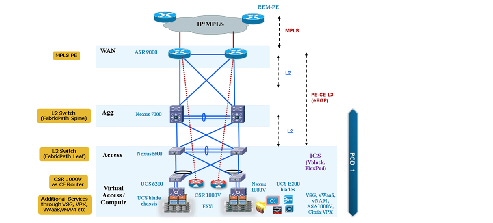
The VMDC VSA 1.0 solution utilizes a hierarchical data center network design for high availability (HA) and scalability. The hierarchical or layered data center design uses redundant switches at each layer of the network topology for device-level failover that creates a highly available transport between end nodes using the network. While the VPC-based Nexus data center fabric could also be utilized, the VMDC VSA 1.0 solution has been validated with a Leaf-Spine FabricPath design using Nexus platforms. Data center networks often require additional services beyond basic packet forwarding such as Server Load Balancing (SLB), firewall, and Network Address Translation (NAT).
These services are provided by virtual service appliances hosted on the Cisco UCS in the VMDC VSA 1.0 solution. Each service approach also supports the deployment of redundant appliances to preserve HA standards set by the network topology. This layered and redundant approach is the foundation of the VMDC design to provide scalability, performance, flexibility, resiliency, and service assurance. VLANs and VXLANs are used to provide tenant isolation within the data center architecture, and BGP or static routing is used to interconnect the different networking and service devices, in addition to utilizing Nexus 1000V vPath for chaining some virtual services.
This multi-layered VMDC VSA data center architecture is comprised of WAN, aggregation, access, and compute layers, with services residing in the compute layer. This architecture allows the addition of data center modules as demand and load increases. It also provides the flexibility to create different logical topologies and insertion of new virtual service devices.
The layers of the VMDC VSA 1.0 architecture are briefly described below:
- WAN/Edge—The WAN or data center edge layer connects the data center to the WAN. Typically, this provides IP or MPLS-based connectivity to the Internet or intranet. The ASR 9010 is used as an MPLS PE router in the VSA 1.0 design, providing L3VPN connectivity to the provider IP/MPLS network. It also provides aggregation of all data center PODs as they connect directly to the ASR 9010 PE. The ASR 9010 is utilized in nV mode, where two physical ASR 9000 devices have a single control plane and appear as a single logical device to adjacent nodes.
- Aggregation—The aggregation layer of the data center provides a consolidation point where access layer switches provide connectivity between servers for multi-tier applications and across the core of the network to clients residing within the WAN, Internet, or campus. This design utilizes Cisco FabricPath technology to provide provisioning simplicity, VLAN flexibility, MAC learning, and high bandwidth Equal-cost Multipathing (ECMP) capabilities in the data center fabric. The Nexus 7010 switches are utilized as the aggregation layer or FabricPath Spine in this solution.
- Access—The access layer of the network provides connectivity for server farm end nodes in the data center. The Nexus 5596 is utilized as the access layer switch or FabricPath Leaf node in this design. The Nexus 5596 connects to multiple UCS fabrics (UCS 6200 Fabric Interconnects and UCS 5100 Blade Chassis with UCS B-series blade servers). Typically, the Nexus 5500, UCS Fabric Interconnects, and UCS Blade Chassis, along with storage resources, are bundled together in ICS stacks such as the VCE Vblock and Cisco/NetApp FlexPod.
- Services—Network and security services, such as firewalls, server load balancers, intrusion prevention systems, application-based firewalls, and network analysis modules, are typically deployed at the data center services layer. In the VMDC VSA 1.0 solution, these services are implemented by virtual appliances residing on the UCS blades. The firewall and VPN services are provided either by the CSR 1000V or ASA 1000V, while the SLB service is provided by the Citrix NetScaler VPX. In addition, the Virtual Security Gateway (VSG) working in conjunction with the Nexus 1000V Distributed Virtual Switch (DVS) provides intra-VXLAN and inter-VXLAN protection to the VMs.
- Integrated Compute Stack—This is the ICS stack, such as FlexPod or Vblock. This typically consists of racks of compute based on UCS, storage and a pair of Nexus 5500 switches aggregating the connections out of the block. The Nexus 5500 Access switch within the ICS provides connectivity both for the LAN (via 10GE Ethernet links) and SAN (via dedicated FC links), and connects to the storage for the ICS stack.
- Virtual Access—Access switch virtualization allows the function of the logical Layer 2 access layer to span multiple physical devices. The Nexus 1000V DVS running on top of the VMware ESXi hypervisor is used in the solution.
The compute and storage layer in the VMDC VSA 1.0 solution has been validated with a FlexPod-aligned implementation using the following components:
- Compute—Cisco UCS 6296 Fabric Interconnect switches with UCS 5108 blade chassis populated with UCS B200 and B230 half-width blades. VMware vSphere 5.1 ESXi is the hypervisor for virtualizing the UCS blade servers.
- SAN—Cisco Nexus 5596 switches provide Fibre Channel (FC) connectivity between the UCS compute blades and the NetApp FAS 6040 storage array.
Figure 2-7 provides a logical representation of the VMDC VSA 1.0 system architecture.
Figure 2-7 VMDC VSA 1.0 System Architecture
VMDC VSA 1.0 Virtual Service Platforms
In this solution, the following virtual nodes provide the listed per-tenant services to cloud users:
–![]() Site-site and remote access IPsec VPN services
Site-site and remote access IPsec VPN services
–![]() Perimeter and Zone-based Firewall (ZBFW) services
Perimeter and Zone-based Firewall (ZBFW) services
–![]() Application visibility and control services
Application visibility and control services
–![]() Inter-VXLAN and Intra-VXLAN security policies
Inter-VXLAN and Intra-VXLAN security policies
–![]() Site-site IPsec VPN services
Site-site IPsec VPN services
–![]() VXLAN Termination and Endpoint (VTEP) services
VXLAN Termination and Endpoint (VTEP) services

Note While VMDC VSA 1.0 was validated with the Citrix VPX virtual SLB appliance, it is now recommended to use the Citrix NetScaler 1000V (Cisco OEM version of the VPX appliance) virtual SLB appliance, with or without vPath traffic redirection. When utilizing the NetScaler 1000V in non-vPath mode, the VSA 1.0 design, logical connectivity models and configurations can be used as-is, with the NetScaler 1000V replacing the VPX appliance. Future VMDC designs will be built around the NetScaler 1000V.
VMDC VSA 1.0 Network Containers
Cloud providers, whether service providers or Enterprises, desire to deploy an IaaS offering with multiple feature tiers and pricing levels. To tailor workload or application requirements to specific customer needs, the cloud provider can differentiate services with a multi-tiered service infrastructure and Quality of Service (QoS) settings. The Cisco VMDC architecture allows customers to build differentiated service tiers and service level agreements that support their tenant or application requirements. Such services can be used and purchased under a variable pricing model. Infrastructure and resource pools can be designed so that end users can add or expand services by requesting additional compute, storage, or network capacity. This elasticity allows the provider to maximize the user experience by offering a custom, private data center in virtual form.
The VMDC VSA 1.0 solution defines a reference multi-tier IaaS service model of Gold, Silver, Bronze, and Zinc tiers. These service tiers (or network containers) define resource and service levels for compute, storage, and network performance. This is not meant to be a strict definition of appliance and resource allocation, but to demonstrate how differentiated service tiers could be built. These are differentiated based on network resources, access methods, stateful services, QoS, compute/storage resources, and application tiers.
The network container is a logical (virtual) segment of the shared (common) physical network resource (end-to-end through the data center) that represents the data center network domain carrying tenant traffic. The physical infrastructure is common to all tenants, but each network device (routers, switches, firewalls, and so forth) is virtualized such that each tenant's virtual network container is overlaid on the common physical network. In the case of virtual service appliances like CSR 1000V, VSG, Citrix VPX etc., each tenant gets an individual instance of the virtual appliance The virtual appliance instance is then a part of the specific tenant network container.
In the VMDC VSA architecture, each tenant gets their own virtual service appliances (redundant appliances for HA) as part of the network container. VLANs are utilized for connecting the tenant routing instance (CSR 1000V) to the tenant VRF instances on the ASR 9000 WAN router. VXLANs (or VLANs) are utilized in the compute layer, to place workloads into and to interconnect the virtual service appliances.
Note For detailed information on the VMDC VSA 1.0 network containers, refer to the VMDC VSA 1.0 Implementation Guide, which can be found at www.cisco.com/go/vmdc.
VMDC VSA 1.0 Gold Network Container (with 2 Zones)
Figure 2-8 shows a logical representation of a VMDC VSA 1.0 Gold service tier network container.
Figure 2-8 VMDC VSA 1.0 Gold Network Container
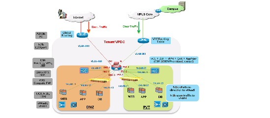
The Gold tenant gets two network (and compute/storage) zones into which to place workloads. Each Gold tenant container has its own set of transport VLANs, compute segment VXLANs and virtual routing instances (CSR 1000V). Each zone in a Gold container has its own compute segment VXLANs and virtual appliances (VPX, VSG). This Gold service tier provides the highest level of sophistication by including the following services:
- Routing (BGP) on the CSR 1000V, to connect the tenant virtual data center to the tenant VRF (or Internet) on the WAN router.
- Access from Internet or MPLS-VPN to tenant container (virtual data center).
- Two zones - PVT and DMZ - to place workloads. Each zone has its own VXLAN segments.
- IPsec Remote-Access VPN on the CSR 1000V, to provide Internet-based secure connectivity for end-users to their virtual data center resources.
- ZBF on the CSR 1000V, to provide stateful perimeter and inter-Zone firewall services to protect the tenant workloads.
- Network Address Translation on the CSR 1000V, to provide Static and Dynamic NAT services to RFC1918 addressed VMs.
- Server Load Balance on the Citrix VPX, to provide L4-7 load balancing and SSL Offload services to tenant workloads.
- Compute firewall on the VSG to provide inter-VXLAN and intra-VXLAN security service to the tenant VMs.
- AVC on the CSR 1000V, to analyze and control application traffic utilizing Network Based Application Control (NBAR), NetFlow, Performance Monitor and QoS.
- WAN Optimization services on the vWAAS, to provide application and bandwidth optimization and caching, utilizing CSR 1000V AppNav-based redirection mechanism.
- Traffic redirection to vWAAS for optimization can also be provided by the Nexus 1000V vPath mechanism; this was not validated in this VMDC VSA 1.0 system.
- Network analysis services on the vNAM, to provide traffic monitoring and analysis. The traffic monitoring can be done by utilizing SPAN or ERSPAN on the Nexus 1000V, ERSPAN on the CSR 1000V or NetFlow on the CSR 1000V or Nexus 1000V.
- Higher QoS SLA and two traffic classes - real-time (VoIP), and premium data.
- Redundant virtual appliances for HA (except for vNAM and vWAAS).
The two zones can be used to host different types of applications to be accessed through different network paths. The two zones are discussed in detail below:
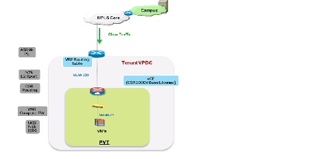
- PVT Zone—The PVT, or Private Zone, and its VMs can be used for cloud services to be accessed through the customer MPLS-VPN network. The customer sites connect to the provider MPLS core and the customer has their own MPLS-VPN (Cust-VRF). The VMDC Data Center Edge router (ASR 9000 PE) connects to the customer sites through the MPLS-VPN (via the Cust-VRF). This Cust-VRF is connected through the data center (Nexus 7000, UCS 6200 etc.) to the customer's CSR 1000V fronting the customer virtual data center. For the VMDC VSA 1.0 Gold tenant, the PVT zone is defined with three server VXLANs. In addition, each tenant is assigned a separate Nexus 1000V VSG instance in the PVT zone. The VSG is used to provide security policies to monitor and protect traffic between the VXLANs and Zones.
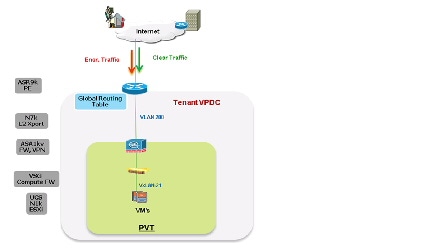
- DMZ—The VMDC VSA 1.0 Gold container supports a DMZ for tenants to place VMs into a DMZ area, for isolating and securing the DMZ workloads from the PVT workloads, and to enable users on the Internet to access the DMZ-based cloud services. The ASR 9000 PE WAN router is also connected to the Internet, and a shared (common) VRF instance (usually global routing table) exists for all Gold tenants to connect to (either encrypted or unencrypted).
In VMDC VSA 1.0, a Gold tenant can choose to have only the PVT Zone, only the DMZ, or both the PVT Zone and DMZ. The CSR 1000V utilizes IOS Zone-Based Firewall (ZBF) to control and secure traffic flows from outside to the zones and between the zones. To facilitate traffic flows between the DMZ and PVT Zones (for example, proxy or web servers in the DMZ, application and database servers in the PVT Zone); appropriate security policies need to be configured on the CSR 1000V ZBF.
The VSG is used to provide compute firewall services for VMs in the PVT Zone and DMZ. Load-balanced traffic for all tiers of Gold tenants is implemented using the Citrix NetScaler VPX, which has one interface in each of the tiers (VXLAN segments). A separate VSG and VPX (pairs with redundancy) are used in the PVT Zone and DMZ.
The following cloud traffic services flows can be enabled in the VMDC VSA 1.0 two-zone Gold service tier:
VMDC VSA 1.0 Silver Network Container
Figure 2-9 shows a logical representation of a VMDC VSA 1.0 Silver service tier network container.
Figure 2-9 VMDC VSA 1.0 Silver Network Container
The Silver tenant gets one network (and compute/storage) zone (PVT) into which to place workloads. Each Silver tenant container has its own set of transport VLANs, compute segment VXLANs, and virtual routing instances (CSR 1000V). This Silver service tier provides the following services:
- Routing (BGP) on the CSR 1000V, to connect the tenant virtual data center to the tenant VRF instance on the WAN router
- Access from MPLS-VPN to tenant container (virtual data center)
- One Zone - PVT - to place workloads, with three VXLAN segments in the zone
- SLB on the Citrix NetScaler VPX to provide L4-7 load balancing and SSL Offload services to tenant workloads
- Compute firewall on the VSG to provide inter-VXLAN and intra-VXLAN security service to the tenant VMs
- Medium QoS SLA with one traffic class - standard data
- Redundant virtual appliances for HA
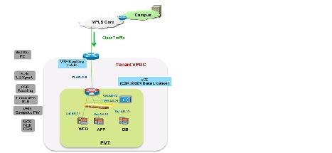
VMDC VSA 1.0 Bronze Network Container
Figure 2-10 shows a logical representation of a VMDC VSA 1.0 Bronze service tier network container.
Figure 2-10 VMDC VSA 1.0 Bronze Network Container
The Bronze tenant gets one network (and compute/storage) zone (PVT) into which to place workloads. Each Bronze tenant container has its own set of transport VLAN, compute segment VXLAN, and virtual routing instances (CSR 1000V). This Bronze service tier provides the following services:
- Routing (BGP) on the CSR 1000V, to connect the tenant virtual data center to the tenant VRF instance on the WAN router
- Access from MPLS-VPN to tenant container (virtual data center)
- One Zone - PVT - to place workloads, with one VXLAN segment in the zone
- Compute firewall on the VSG to provide inter-VXLAN and intra-VXLAN security service to the tenant VMs
- Lower QoS SLA with one traffic class - premium data
- Redundant virtual appliances for HA
VMDC VSA 1.0 Zinc Network Container
Figure 2-11 shows a logical representation of a VMDC VSA 1.0 Zinc service tier network container.
Figure 2-11 VMDC VSA 1.0 Zinc Network Container
The Zinc tenant gets one network (and compute/storage) zone into which to place workloads. Each Zinc tenant container has its own set of transport VLAN, compute segment VXLAN, and virtual routing instances (ASA 1000V). This Zinc service tier provides the following services:
- Routing (static) on the ASA 1000V, to connect the tenant virtual data center to the Internet routing table on the WAN router
- Access from Internet tenant container (virtual data center)
- One Zone - PVT - to place workloads, with one VXLAN segment
- IPsec Site-to-site VPN on the ASA 1000V, to provide Internet-based secure connectivity for customer sites to their virtual data center resources
- Perimeter firewall on the ASA 1000V, to provide stateful perimeter firewall services to protect the tenant workloads
- NAT on the ASA 1000V, to provide static and dynamic NAT services to RFC1918 addressed VMs
- SLB on the Citrix NetScaler VPX to provide L4-7 load balancing and SSL Offload services to tenant workloads
- Compute firewall on the VSG to provide perimeter and intra-VXLAN security service to the tenant VMs
- Lower QoS SLA with one traffic class - standard data
- Redundant virtual appliances for HA
CSR 1000V Role in DRaaS Architecture
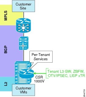
The VMDC VSA 1.0 tenancy model is designed with dedicated CSR1000v per tenant. Apart from being a virtual router, CSR would be used for other functionality within the DRaaS architecture. The roles are defined below, as shown in Figure 2-12:
- Aggregation router-Layer 3 gateway for server VLANs
- Routing
- IPSec (AES)-Encryption of tenant traffic over OTV (Data Security)
- Firewall-Zone-based Firewall policy for server traffic
- OTV for Layer 2 extension
- LISP for VM mobility
Figure 2-12 CSR Role in DRaaS Architecture
CSR Interface Usage and Functionality
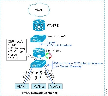
Within the VMDC VSA network containers, CSR 1000V has Layer 3 interfaces for each server VLAN and uplink interfaces peered with the PE device (Figure 2-13). An additional 802.1q Layer 2 trunk interface is configured on the CSR to support DRaaS. The uplink interface will be used as join interface within OTV and the Layer 2 trunk interface will be used as an internal interface with service instances linking to VLAN tags within the bridge group. Zone-based firewall policies will be implemented as per VMDC architecture.
Figure 2-13 VMDC Network Container
Data Center Interconnect Design Considerations
The Cisco OTV technology on the CSR1000V will be utilized in this DRaaS Solution to provide Layer 2 extension and connectivity between the Enterprise data center and Provider data center (Figure 2-14).
OTV is an IP-based functionality designed to provide Layer 2 extension capabilities over any transport infrastructure: e.g., Layer 2-based, Layer 3-based, IP switched, label switched. The only requirement from the transport infrastructure is providing IP connectivity between remote data center sites. OTV enables Layer 2 connectivity between separate Layer 2 domains while keeping these domains independent and preserving the fault-isolation, resiliency, and load-balancing benefits of an IP-based interconnection. OTV can be thought of as MAC-address routing, in which destinations are MAC addresses, and next hops are IP addresses. OTV simply maps MAC address destinations to IP next hops that are reachable through the network cloud. Traffic destined for a particular MAC address is encapsulated in IP and carried through the IP cloud to its MAC-address routing next hop. OTV encapsulates the MAC frame in an IP/UDP packet.
Typical DCI deployment scenarios like VPLS on ASR9000, or OTV on Nexus7000 or ASR1000, are router-based, multi-tenant, and provider-managed scenarios where the data center WAN edge router (ASR9000, ASR1000) or data center aggregation router/switch (Nexus7000) is utilized for providing DCI and Layer 2 extension for multiple tenants. These deployment scenarios can be point-to-point or multi-point (depending on the DCI technology or platform), and have scale constraints based on the number of sites, VLANs, MACs, bridge-domains, and pseudowires.
However, the DRaaS Solution utilizes a per-tenant CSR1000V for OTV-based DCI and Layer 2 extension. This will be a per-tenant point-to-point DCI scenario and will not have the scale constraints associated with multi-tenant DCI scenarios. OTV is first supported on the CSR1000V in IOS-XE release 3.10.
Figure 2-14 Per-Tenant CSR 1000V as OTV Edge Device
OTV Terminology
- Site—A site is a single or multi-homed connected network that is typically under the control of a single organization. Sites are connected together via edge devices that operate in an overlay network. The edge devices provide Layer 2 connectivity among the sites.
- Edge Device (ED)—The edge device connects the site to the (WAN/MAN) core. The edge device is responsible for performing all the OTV functions. A given site can have multiple OTV edge devices.
- Internal Interface—The internal or access interfaces are those interfaces on the edge devices that face the site. Internal interfaces behave as regular Layer 2 interfaces. Spanning Tree Bridge Protocol Data Units (BPDUs) are received and processed on the internal interfaces, as they would be on a regular LAN bridge device.
- Join Interface—The join interface is the interface of the edge device that faces the core. Join interface is typically a point-to-point routed interface connecting the sites to the core. They are used to join the core multicast groups used by OTV.
- Overlay Interface—The overlay interface is a logical multi-access, multicast-capable interface. The overlay interface encapsulates Layer 2 frames in IP unicast or multicast headers. The overlay interface is realized by overlaying one or more physical core-facing interfaces.
OTV Packet Flow
When an ED receives a Layer 2 frame on an internal interface, OTV performs the MAC table lookup based on the destination address of the Layer 2 frame. If the frame is destined to a MAC address that is reachable through another internal interface, the frame is forwarded on that internal interface. OTV performs no other actions and the processing of the frame is complete.
If the frame is destined to a MAC address that was learned over an overlay interface, OTV performs the following tasks:
- Strips the preamble and frame check sequence (FCS) from the Layer 2 frame.
- Adds an OTV header to the Layer 2 frame and copies the 802.1Q information into the OTV header.
- Adds the IP address to the packet based on the initial MAC address table lookup. This IP address is used as the destination address for the IP packet that is sent into the core switch.
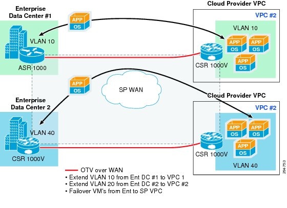
OTV traffic appears as IP traffic to the network core. At the destination site, the ED performs the reverse operation and presents the original Layer 2 frame to the local site. The ED determines the correct internal interface to forward the frame on, based on the local MAC address table. Figure 2-15 shows the use of CSR/OTV to enable partial failovers between the enterprise and SP data centers. The CSR 1000V within the SP network container will be used as an OTV edge device. The traffic from the Enterprise users always flows through the primary Enterprise data center during normal operations and during partial failover scenarios. The network services like firewall and load balancing will also be provided from the Enterprise data center during normal and partial failover scenarios. Users will be able to access the recovery environment directly from the SP cloud and obtain all the related network services from the SP cloud only during full failover of the enterprise site into the service provider’s VPC.
In this scenario, inter-VLAN routing for failed-over VMs in the provider cloud will happen locally in the Provider data center. Load balancing services for the failed-over VMs will be provided by the SLB in the Provider data center. The ZBFW residing on CSR 1000V in the Provider data center will provide firewall services for the failed-over VMs. The VSG in the Provider data center will provide compute firewall services for the migrated VMs
In partial failover scenario, since dual gateways exist in each VLAN (Enterprise and SP data center), First Hop Redundancy Protocol (FHRP) filtering (HSRP localization) needs to be configured for egress path optimization. The replicated traffic between the enterprise and SP data centers will always flow through the OTV Tunnel. In addition, the server-to-server communication in a partial failover scenario will flow through the OTV Tunnel. All the east-west traffic flowing through OTV will be encrypted via IPsec.
Figure 2-15 OTV Deployment to Enable Partial Failovers
Network Encryption
CSR 1000v will provide OTV transport as well as encryption via IPsec for the replicated traffic between the Enterprise and service provider data centers. The OTV packets will be encrypted and then be transported over the IP WAN. IPsec crypto map will be applied on the overlay interface.
An IPsec over OTV provides data security over LAN extension between data centers. CSR1000V supports Advanced Encryption Standard (AES) and Triple Data Encryption Standard (3DES) encryption. 3DES is CPU-intensive and offers lower throughput compared to AES. Apart from an IPsec header, packets over OTV have an OTV header. This reduces packet MTU. It is important to configure a proper MTU on the overlay interface and IS-IS to prevent packets from being fragmented. Packet fragmentation lowers the throughput considerably based on the findings; the ideal MTU size is 1372 bytes.
Cisco UCS for Hot Standby Computing Resources
Today, many service providers' DRaaS implementations leverage dedicated compute environments for large or compliance-sensitive tenants. This typically involves dedicating a number of hosts to a particular tenant. These dedicated compute models may also be used in many cases where the backup or replication technology is not designed to support multi-tenancy or where the customer requires extensive administrative access (such as a dedicated vCenter) and the provider chooses to address this by building a private cloud environment per tenant.
Cisco's DRaaS Solution provides an alternative dynamic compute resource allocation approach for minimizing compute resource CAPEX and OPEX costs for DRaaS implementations. This "on demand," or "hot standby," approach is made possible by the stateless computing capability of the Cisco UCS using "service profiles" to define servers in software rather than in the actual underlying hardware.
Cisco UCS stateless computing has quickly become the solution behind the most successful DRaaS and ICDR solutions due to the industry-changing approach to disaster recovery. Regardless of the underlying replication technology, whether storage-based, hypervisor-based, host-based, or backup-based, Cisco UCS aligns with the underlying hardware requirements and extends the flexibility and agility to business continuity (BC) and disaster recovery.
A DR solution based on Cisco UCS provides the following:
- Removal of deployment barriers with a replication-agnostic solution that installs seamlessly into the existing infrastructure.
- Support for any underlying OS or hypervisor.
- Centralized DR management solution, regardless of the physical or virtual placement.
- Complete virtual awareness so the customer can make changes to the production environment with no impact to BC/DR processes.
- Technical infrastructure for secure and segmented multi-tenant DR access.
- Ability to dedicate compute environments easily and cost-effectively on a per-tenant basis, allowing service providers to gain economies of scale even when using single-tenant storage, replication or backup technologies.
Using these approaches, service providers can increase the profitability of existing private cloud DRaaS models. In addition, they can easily deploy and support enterprise-centric replication and backup solutions that have historically been challenging to support in multi-tenant environments.
UCS Service Profiles and Templates
Cisco Unified Computing System Overview
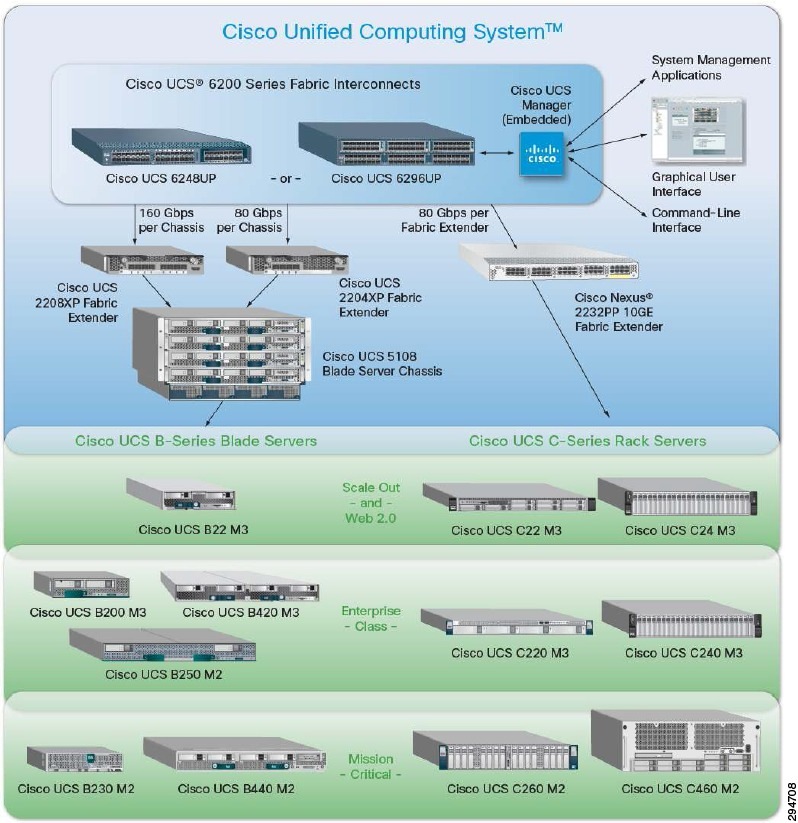
The Cisco Unified Computing System (Cisco UCS) is a next-generation data center platform that unites computing, networking, storage access, and virtualization resources into a cohesive system designed to reduce TCO and increase business agility. The system, which integrates a low-latency, lossless 10 Gigabit Ethernet unified network fabric with enterprise-class, x86-architecture servers, is an integrated, scalable, multi-chassis platform in which all resources participate in a unified management domain. See Figure 2-16.
Figure 2-16 Cisco Unified Computing System
Cisco UCS 6200 Series Fabric Interconnect
The Cisco UCS 6200 Series Fabric Interconnect is a core component of the Cisco Unified Computing System, providing both network connectivity and management capabilities for the system. The Fabric Interconnect supports line-rate, low-latency, lossless 10 Gigabit Ethernet, Fibre Channel over Ethernet (FCoE), and Fibre Channel functions.
The Fabric Interconnects constitute the management and communication backbone for the Cisco UCS B-Series Blade Servers and 5100 Series Blade Server Chassis, in addition to the Cisco UCS C-Series Rack Servers when connected through a Cisco Nexus Fabric Extender. All chassis and servers attached to the Fabric Interconnects become part of a single, highly available management domain. In addition, by supporting unified fabric, they provide both the LAN and SAN connectivity for all servers within its domain.
From a networking perspective, the Fabric Interconnects support multiple traffic classes and use a cut- through architecture, with deterministic, low-latency, line-rate 10 Gigabit Ethernet on all ports, resulting in a switching capacity of 2 terabits (Tb), and 320-Gbps bandwidth per chassis, independent of packet size and enabled services.
Significant TCO savings come from an FCoE-optimized server design in which network interface cards (NICs), host bus adapters (HBAs), cables, and switches can be consolidated, thereby increasing the reliability, efficiency, and scalability of Ethernet networks. See Table 2-1 .
For more information about the Cisco UCS 6200 Series Fabric Interconnects, visit http://www.cisco.com/en/US/products/ps11544/index.html or contact your local account representative.
Cisco UCS Manager
Cisco UCS Manager provides unified, embedded management of all software and hardware components of Cisco UCS across multiple chassis, rack servers, and thousands of virtual machines. Cisco UCS Manager manages Cisco UCS as a single entity through an intuitive GUI, a CLI, or an XML API for comprehensive access to all Cisco UCS Manager functions.
Cisco UCS Manager is embedded on a pair of Cisco UCS 6200 Series Fabric Interconnects using a clustered, active-standby configuration for high availability. Cisco UCS Manager participates in server provisioning, device discovery, inventory, configuration, diagnostics, monitoring, fault detection, auditing, and statistics collection.
Connectivity to the Cisco UCS 5100 Series blade chassis is maintained through the Cisco UCS 2100 or 2200 Series Fabric Extenders in each blade chassis. Connectivity to the Cisco UCS C-Series Rack Servers is maintained through the Cisco Nexus 2232 Fabric Extenders.
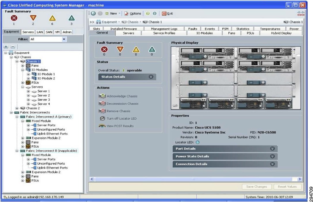
Cisco UCS Manager has a GUI as well as a CLI for use by server, network, and storage administrators. Cisco UCS Manager also provides a powerful XML API for integration with existing data center systems management tools. Some examples of additional management interfaces are Intelligent Platform Management Interface (IPMI); keyboard, video, and mouse (KVM); serial-over-LAN (SoL); and Simple Network Management Protocol (SNMP). The XML interface allows the entire system to be monitored or configured externally by higher-level systems management tools from Cisco's many ecosystem partners. See Figure 2-17.
Figure 2-17 Cisco Unified Computing System Manager User Interface
For more information about the Cisco UCS Manager, visit http://www.cisco.com/en/US/products/ps10281/index.html or contact your local account representative.
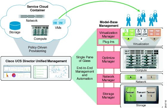
Cisco UCS Director
The Cisco UCS Director provides unified, highly secure management for the industry's leading converged infrastructure solutions, which are based on the Cisco UCS and Cisco Nexus platforms. Cisco UCS Director extends the unification of computing and network layers through Cisco UCS to provide data center administrators with comprehensive visibility and management capability. It supports NetApp FlexPod and ExpressPod, EMC VSPEX, and Virtual Computing Environment (VCE) Vblock systems, based on the Cisco UCS and Cisco Nexus platforms. See Figure 2-18.
Figure 2-18 Cisco Unified Computing System Director Overview
Cisco UCS Director was formerly known as Cloupia Unified Infrastructure Controller and as Cisco Cloupia.
Cisco UCS Director is not a replacement for Cisco UCS Manager. Rather, Cisco UCS Director uses orchestration to automate some of the steps required to configure a Cisco UCS domain. In this way, Cisco UCS Director provides a statistical analysis of the data and provides a converged view of the data center.
After you add a Cisco UCS domain to Cisco UCS Director as a Cisco UCS Manager account, Cisco UCS Director provides you with complete visibility into the Cisco UCS domain. In addition, you can use Cisco UCS Director to manage and configure that Cisco UCS domain.
You can use Cisco UCS Director to perform management, monitoring, and reporting tasks for physical and virtual devices within a Cisco UCS domain.
Configuration and Administration
You can create and configure Cisco UCS hardware and software components in Cisco UCS Director, such as:
Monitoring and Reporting
You can also use Cisco UCS Director to monitor and report on your Cisco UCS domains and their components, including:
Figure 2-19 UCS Director Summary View of Compute Resources
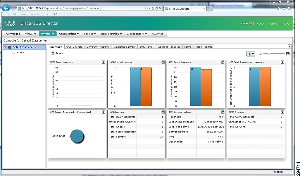
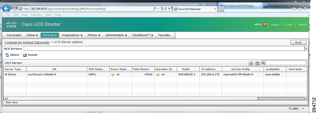
Figure 2-20 UCS Director Drill Down to Server-Specific Details
Cisco UCS Management Tasks You Cannot Perform in Cisco UCS Director
You cannot use Cisco UCS Director to perform the following system management tasks within a Cisco UCS domain:
For more information about the Cisco UCS Director, visit http://www.cisco.com/en/US/products/ps13050/index.html or contact your local account representative.
Service Profiles
In the Cisco Unified Computing System, a service profile adds a layer of abstraction to the actual physical hardware. The server is defined in a configuration file, which is stored on the UCS 6200 Series Fabric Interconnects and can be associated with physical hardware in a simple operation from the UCS Manager. When the service profile is applied, the UCS Manager configures the server, adaptors, Fabric Extenders, and Fabric Interconnects as specified in the service profile. The service profile makes the physical hardware transparent to the OSs and VMs running on it, enabling stateless computing and maximization of data center resources.
A number of parameters can be defined in the service profile depending on the environment requirements. Administrators can create policies to define specific rules and operating characteristics, and be referenced in the service profiles to ensure consistent configuration across many servers. Updates to a policy can be propagated to all servers that reference that policy in their service profile immediately, or in the case of firmware updates, at the next power cycle event.
Service profiles enable rapid provisioning of servers with consistent operational parameters and high availability functionality. They can be configured in advance and used to move servers to a new blade, chassis, or rack in the event of a failure. See Table 2-2 .
|
Obtained from defined MAC pool |
||
Service Profile Parameters and Administrative Scope
Service profile policies can be administered by the traditional network, server, and storage organizations using role-based access control (RBAC) on the UCS Manager. A super- administrator defines initial roles and specifies which administrators are allowed to assume what roles. Cisco UCS Manager comes with server, network, and storage administrator roles predefined. These roles can be modified, merged, and deleted, and new roles can be created to fit the organization model in place. Coordination between roles is simplified on the Cisco
UCS because, although roles are separated, an administrator assuming one role can view the actions taken by administrators having other roles. For example, a storage administrator can set up Fibre Channel configuration options to see the choices that a network administrator has made when setting up network options; the same is true for the settings applied by the server administrator. Visibility between roles helps eliminate ambiguity and reduce the chance of error due to miscommunication or lack of communication that may occur when administrators instead rely on phone calls, tickets, spreadsheets, or email.
Depending on the size of the organization, various levels of administrator authority can be defined through roles. Creating a set of layered roles allows SMEs to focus on high-level configuration issues and allows lower-level administrators to implement the configurations. For example:
- Server, network, and storage SME roles might define a set of policies appropriate for their specific domains. For instance, each expert might define a set of domain- specific choices appropriate for provisioning each specific type of server, such as a web, database, or application server.
- The next level of administrator might be allowed by role to choose from the policies defined by the SMEs to create service profiles or templates appropriate for specific server types. For instance, this level of administrator might be allowed to choose the database server network adapter profile and the database server host -bus adapter profile (along with other profile s) to create a database server template. This administrator might also be allowed to use the template to provision servers.
- A lower-level administrator might be allowed to use only existing templates to provision servers, with no choice of specific policies allowed.
Table 2-3 shows the resource layers in a Cisco UCS and the kinds of policies that might be created for each layer by each role. The resulting service profile or template at the right illustrates the result of choosing from the policies defined by the SMEs.
Templates for Service Profiles
The advantages of the service profile can be extended further when server-specific parameters such as UUID, MAC address, and WWN are themselves parameterized and the service profile is converted to a template. The template can be used to rapidly deploy new servers with consistent general parameters and unique server-specific parameters. The lifecycle of a service profile starts with its creation, which can happen in one of three ways using the UCS Manager:
- Manually—Create a new service profile starting with all default values.
- Via Template—Create a new service profile from a template.
- Cloning—Create a new service profile from an existing service profile. Two types of templates exist: initial and updating.
–![]() The initial template is used to create a service profile with unique server-specific parameters, but with no linkage back to the template itself. Any subsequent updates to the template are not propagated to the service profile of the server deployed from that template. If changes to the template are also required in any of the service profiles created from the template, the changes need to be manually made to each service profile.
The initial template is used to create a service profile with unique server-specific parameters, but with no linkage back to the template itself. Any subsequent updates to the template are not propagated to the service profile of the server deployed from that template. If changes to the template are also required in any of the service profiles created from the template, the changes need to be manually made to each service profile.
–![]() Conversely, service profiles that are created from an updating template will maintain a link back to the template and will inherit any subsequent changes made to the template. Most updates will be inherited immediately, while others like firmware updates will be made at the next bootup of the server.
Conversely, service profiles that are created from an updating template will maintain a link back to the template and will inherit any subsequent changes made to the template. Most updates will be inherited immediately, while others like firmware updates will be made at the next bootup of the server.
Once a service profile template is created, it can be used to deploy single or multiple instances using unique identifiers (UIDs) in several ways:
- Manually—UIDs supplied by server administrator at deployment time. This is typically used with a few stand-alone service profiles rather than templates.
- Automatically—UIDs generated by the template at runtime. Unique names are created for each server and MAC, WWN, etc. are pulled from defined pools.
- Programmatically—Controlled by external software leveraging UCS Manager APIs.
Hot Standby Compute Resources
When a disaster event is declared and disaster recovery is initiated, the CSP will need to provide adequate compute resources to allow servers to be recovered at a predefined CSP Data Center. The following discussion provides an overview of several validated use cases for how additional compute resources can be brought online when needed and seamlessly added to a Cloud Data Center that is providing DR services.
One of the advantages of Cisco UCS is the ability to configure physical blade and rack mount servers with service profiles that can be stored on the UCS Manager. Service profile templates, resource pools, and policies can be used to dynamically configure service profiles with IP/MAC addresses assignments, boot policies, firmware version, BIOS policies, etc. Once the service profile is associated to a server, the physical server can be booted up and configured according to the policies and resources defined. Each service profile is unique and can only be associated to a single server.
The use cases discussed in this paper are based upon the assumption that all service profile templates, resource pools, policies, and, optionally, service profiles have been pre-provisioned prior to a disaster event being declared. When a disaster event is declared, the required on- demand compute resources can be brought online by simply associating the proper service profile and booting the server from the UCS Manager via the user interface or API.
The CSP's managed data center is responsible for making sure that sufficient compute resources are available in the event that an Enterprise tenant declares a DR event. The following use cases are based upon VMware's vCenter being used to manage and monitor the Enterprise tenant's compute environments. The CSP's DR data center configuration, at a minimum, should guarantee that enough CPU and memory resources are available so that all VMs can be powered up and brought online if a DR event is declared by the Enterprise.
Use Case-Physical-to-Physical Recovery (Blade)
In this use case, disaster recovery of protected sources in the enterprise data center will be performed in the SP data center using on-demand compute resources from a pool of UCS B- Series blade servers, which provide the following:
- Allow servers to be recovered with any operating system.
- Pre-stage qualified UCS firmware versions for BIOS, adapters, and Cisco Integrated Management Controller (CIMC).
- Pre-configure network and SAN interfaces with the correct VLANs, management IP addresses, and World Wide Port Names (WWPN).
- Standby hardware resources can remain unassociated until needed.
Use Case-Physical-to-Physical Recovery (Rack Mount)
In this use case, disaster recovery of protected sources in the enterprise data center will be performed in the service provider data center using on-demand compute resources from a pool of UCS C- Series rack mount servers, which provide the following:
- Separate Fabric Extender / IO Modules used by UCS Manager to integrate C200 servers.
- Allow servers to be booted with any operating system.
- Standby hardware resources can remain unassociated until needed.
- Pre-stage qualified UCS firmware versions for BIOS, adapters, and CIMC.
- Pre-configure network and SAN interfaces with the correct VLANs, management IP addresses, and WWPNs.
Use Case-Capacity Expansion at Time of Disaster Recovery
In this use case, disaster recovery will be performed using the UCS Director to execute both configuration and deployment workflows at the time of the DR event. This solution is independent of data replication technology and runbook automation tool. Protected VMs at the disaster site are not active until recovery and do not require compute resources. Compute resources are required only when the DR event occurs. Data integrity of protected VM can be accomplished via snapshots, sync and async writes, or any available backup solutions. Runbook automation technology can be any commonly used solutions such as the SRM, Zerto, InMage or any other available runbook automation solutions.
- Automated installation of the operating system from the TFTP/FTP server to the desired volume to allow the host to boot.
- Pre-defined UCS firmware versions for BIOS, adapters, and CIMC are configured and installed.
- Network interfaces with the correct VLANs and management IP addresses are pre - configured.
- UCS Director and UCS Baremetal Agent provide a completely automated workflow for the provisioning of recovered hosts.
- Standby hardware resources can remain unassociated until needed.
Deployment Considerations
The following sections describe deployment considerations for OTV, ITV Mobility, and LISP.
High Availability (HA)
Recommended OTV deployment should use a single CSR 1000V router at each site, utilizing the VMware HA mechanism for high availability. This will be acceptable for most customers and will prove more cost effective (half as many licenses required).
Virtual Extensible LAN (VXLAN)
The DRaaS Solution will use traditional dot1q VLANs within the SP VPC instead of the VXLANs because of limitations with VXLAN unicast mode and MAC distribution (CSCuf60643). Dynamic MAC distribution is required for OTV and is not supported with VXLAN.
A VXLAN supports two different modes for flood traffic:
- Multicast Mode—A VXLAN uses an IP multicast network to send broadcast, multicast, and unknown unicast flood frames. Each multicast mode VXLAN has an assigned multicast group IP address. When a new VM joins a host in a multicast mode VXLAN, a Virtual Ethernet Module (VEM) joins the assigned multicast group IP address by sending Internet Group Management Protocol (IGMP) join messages. Flood traffic, broadcast, multicast and unknown unicast from the VM is encapsulated and is sent using the assigned multicast group IP address as the destination IP address. Packets sent to known unicast MAC addresses are encapsulated and sent directly to the destination server VTEP IP addresses.
- Unicast-Only Mode—A VXLAN uses each VEM's single unicast IP address as the destination IP address to send broadcast, multicast, and unknown unicast flood frames of the designated VTEP on each VEM that has at least one VM in the corresponding VXLAN. When a new VM joins the host in a unicast-mode VXLAN, a designated VTEP is selected for receiving flood traffic on that host. This designated VTEP is communicated to all other hosts through the Virtual Supervisor Module (VSM). Flood traffic (broadcast, multicast, and unknown unicast) is replicated on each VEM's
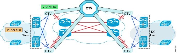
Overlapping VLANs
As Enterprises and service providers extend their data centers for Business Continuity or Workload Mobility, it is likely that overlapping VLAN allocations will exist across data centers. Therefore, we could implement a VLAN translation mechanism to overcome this issue, as described in Figure 2-21. This function will translate a local VLAN to a remote VLAN in a different site (VLAN in the West Site corresponds to a different VLAN in the East Site).
Figure 2-21 OTV VLAN Translation between Sites Layer 2
Use of BDI as Default Gateway on CSR 1000V
Currently, Bridge Domain Interface (BDI) is not supported through OTV. In other words, you cannot ping to the BDI interface in a remote OTV site. IS-IS does not advertise a BDI MAC address, so OTV does not know how to reach the BDI interface in the remote site. You can only ping to the BDI interface within the same site.
Although it is advisable to use BDI as the default gateway on CSR 1000V, the DRaaS 2.0 Solution will use the Layer 3 interfaces as default gateways since BDI is not supported for OTV.
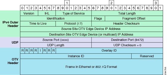
OTV and MTUs
OTV adds 42 bytes in the IP header packets, thus requiring a larger maximum transmission unit (MTU) for traffic to pass (Figure 2-22). Configure the join interface and all Layer 3 interfaces that face the IP core between the OTV edge devices with the highest MTU size supported by the IP core. OTV sets the Don't Fragment (DF) bit in the IP header for all OTV control and data packets so that the core cannot fragment these packets.
Figure 2-22 OTV UDP IPv4 Encapsulation
Two ways exist to solve this problem:
1.![]() Configure a larger MTU on all interfaces where traffic will be encapsulated, including the join interface and any links between the data centers that are in an OTV transport.
Configure a larger MTU on all interfaces where traffic will be encapsulated, including the join interface and any links between the data centers that are in an OTV transport.
2.![]() Lower the MTU on all servers so that the total packet size does not exceed the MTU of the interfaces where traffic is encapsulated.
Lower the MTU on all servers so that the total packet size does not exceed the MTU of the interfaces where traffic is encapsulated.
IP Mobility Design Considerations
The ability to support partial failovers is improved by distributing physical compute and network resources between data centers that are geographically distributed over long distances. Geographic distribution provides higher elasticity and almost unlimited flexibility of the resources required to dynamically deploy VM loads.
The network side can transparently support distributed applications by extending Layer 2 between multiple sites. Yet by definition, the Layer 3 traffic carried between users and active applications through the cloud does not have native knowledge of the physical IP device locations, other than the network prefix given through the most significant bit-group of the IP address. The IP subnet is a logical visible subdivision of the network that is usually limited to the local network. It therefore delimits its broadcast domain defined by the system mask. the enterprise or service provider network team usually establishes the IP subnet. In general, an IP subnet addresses a set of IP equipment that belongs to the same VLAN.
Traditionally, if an IP subnet or a VLAN is associated with a physical location inside a data center, with the concept of interconnecting cloud resources, the broadcast domain is stretched over the distances that separate the data centers (DCI theoretically can be established up to unlimited distances with Layer 2 over Layer 3 transport). Therefore, the concept of location induced natively by the IP subnet subdivision loses one of its original functions of localization.
Thus, depending on the distance between the remote sites, the native routing mechanism can have an impact on performance for three major types of communication in partial failover scenarios:
1.![]() Traffic from the client to the server
Traffic from the client to the server
2.![]() Traffic from the server to the client
Traffic from the server to the client
3.![]() Traffic from server to server (such as in a multi-tier application)
Traffic from server to server (such as in a multi-tier application)
Server-to-Server Traffic
When a server migrates from one site to another, it must return the traffic to its default gateway because its IP address schema remains the same regardless of its physical location. Since one IP address (or virtual IP addresses [VIP]) exists for a given default gateway per subnet, this implies that after the migration of a logical server, the traffic must be returned to the original site where the active default gateway stands. In a complex multi-tier architecture, routers and firewalls are usually enabled to improve the communication and security between the tiers.
If, for example, a solution built with a three-tier application (e.g., Web Server, Application, and Database tiers) is moved from one data center to another, the traffic between each tier will have to return to the site where the gateways or firewalls are active. If we add to that the different network services required for optimization and data security (load balancer, SSL termination, IPS) enabled at different tiers, then up to ten round trips for a simple query may occur. Consequently, depending on the distance between the data centers, the latency for a request may be significantly affected (i.e., an additional 10 to 20 ms for 100 km using dedicated fiber for a 10 round trips).
It is therefore crucial that the inter-application-tier or server-to-server traffic is controlled well to minimize the "ping-pong" effect.
Cisco supports deployment options for enabling the same default gateway functionalities in different data center sites (FHRP localization). This functionality is completely transparent to the application layer as well as to the network layer. By activating this IP localization service, after the failover of VMs it is possible to use a local default gateway configured with the same IP identification (same virtual MAC addresses and virtual IP) that were defined on the original site.
Server-to-Client Traffic
The same function of IP localization can be applied to outbound traffic so that the responses from a server sent to an end user can exit through its local WAN access without returning the session to the default gateway of origin.
However, it is imperative that when stateful services are deployed, the return traffic remains symmetrical with the incoming flows. This ensures the security of sessions without disrupting established sessions. It is therefore important to involve the service of IP localization that exists for outgoing traffic with the other optimizations mechanisms available for the ingress traffic client to server.
In the case of remote a DRaaS use case, the network services like firewall and load balancing will be always running from the enterprise premise as long as the enterprise data center is active and in partial failover scenarios. Within this use case, the client-to-server and the server-to-client traffic will flow through the enterprise data center to maintain symmetrical flows.
Only in the case of a full failover of applications into the service provider cloud, the virtualized devices will be brought up in the service provider's VMDC cloud environment and the necessary network services will be offered from the Cloud. In this scenario, the Client-to-Server and Server-to-Client will be flowing through the service provider VMDC Cloud.
Client-to-Server Traffic
When a user accesses an application running in a distant resource, the client must be able to use the optimal path and be dynamically redirected to the data center supporting the active application or VM. However, as explained previously, the routed Layer 3 network cannot determine the physical location of an IP device within the same subnet when it is stretched between different locations.
In the first use case of remote DRaaS, the Network Services will be always running from the enterprise data center unless a full failover occurs and the Client-to-Server traffic is expected to be flowing through the enterprise side.
Cisco provides a number of IP localization services that combined with other IP functions, support path optimization:
The Cisco Locater/ID Separation Protocol Technology in extended subnet mode with OTV Layer 2 extension on the CSR1000V will be utilized in this DRaaS 2.0 Solution. This provides IP mobility between data centers within SP Cloud for the (VPC to VPC) In-Cloud replication use case.
The Cisco LISP Virtual Machine Mobility (LISP VM-Mobility) solution allows any host to move anywhere in the network while preserving its IP address. The capability allows members of a subnet to be dispersed across many locations without requiring any changes on the hosts and while maintaining optimal routing and scalability in the network. LISP is a network architecture and a set of protocols that implements a new semantic for IP addressing. LISP creates two namespaces and uses two IP addresses: Endpoint Identifiers (EIDs), which are assigned to end-hosts, and Routing Locators (RLOCs), which are assigned to devices (primarily routers) that make up the global routing system. Performing this separation offers several advantages, including:
- Improved routing system scalability by using topologically-aggregated RLOCs
- Provider-independence for devices numbered out of the EID space (IP portability)
- Low-OPEX multi-homing of end-sites with improved traffic engineering
- IPv6 transition functionality
- IP mobility (EIDs can move without changing - only the RLOC changes!)
LISP is a simple, incremental, network-based implementation that is deployed primarily in network edge devices. It requires no changes to host stacks, DNS, or local network infrastructure, and little to no major changes to existing network infrastructures.
LISP is a simple, incremental, network-based implementation that is deployed primarily in network edge devices. It requires no changes to host stacks, DNS, or local network infrastructure, and little to no major changes to existing network infrastructures.
LISP Overview
To understand LISP, it is important to understand the concept of "Location to Identity Separation." See Figure 2-23.
Figure 2-23 Mobility with Location/ID Protocol Technology
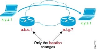
In traditional IP, the IP edge routing subnets are advertised all over the network using either an IGP or an EGP. Advertising any host address (subnet mask /32) occurs rarely; most of the time subnet larger or equal to /24 is used. Because all routes are advertised everywhere and installed in the forwarding plane in IP, limiting the amount of entries is important. By doing so, IP subnets are strictly limited to a geographical area and a subnet is only managed by one pair of router, which is the default gateway. This implies that if a node moves location, then its IP address must be updated accordingly to the local default gateway. This constraint is very strong and cumbersome; in order to escape from it, we see across sites more and more VLAN extension with all the drawbacks this approach can raise.
With LISP, such a constraint disappears; LISP splits the edge ID (EID) from the Routing Location (RLOC), allowing any host to move from location to location while keeping its identity. LISP architecture is composed of several elements:
–![]() Registers the EID address space for which it has authority
Registers the EID address space for which it has authority
–![]() Identified by one (or more) RLOCs
Identified by one (or more) RLOCs
–![]() Receives and de-encapsulates the LISP frames
Receives and de-encapsulates the LISP frames
–![]() The database where all EID/RLOC association are stored
The database where all EID/RLOC association are stored
–![]() Can simply be deployed on a pair of devices for low scale implementation
Can simply be deployed on a pair of devices for low scale implementation
–![]() Or it can be a hierarchy of devices, organized like a DNS system for large scale implementation (LISP-DDT)
Or it can be a hierarchy of devices, organized like a DNS system for large scale implementation (LISP-DDT)
–![]() Sends request toward the Map resolver
Sends request toward the Map resolver
–![]() Populates its local map-cache with the learned association
Populates its local map-cache with the learned association
–![]() Responsible for performing the LISP encapsulation
Responsible for performing the LISP encapsulation
–![]() Receives the request and selects the appropriate map server
Receives the request and selects the appropriate map server
–![]() The point of interconnection between an IP network and a LISP network, playing the role of ITR and ETR at this peering point.
The point of interconnection between an IP network and a LISP network, playing the role of ITR and ETR at this peering point.
An ETR is authoritative for a subnet, and registers it using a 'map-register' message to the map server. When triggered on the data-plane by a packet destined to a remote EID, the ITR performs a "map-request" toward the map-resolver, which forwards it to the right map-server, which then forwards it to the authoritative ETR. The ETR replies to the requesting ITR using a "map-reply" message. The map-reply message contains a list of the RLOCs having the capability to reach the requested EID along with their characteristic in terms of priority of usage and weighted load repartition.
Figure 2-24 shows LISP-ESM deployment using CSR 1000V with in VMDC VSA 1.0 architecture.
Figure 2-24 LISP & OTV Roles and Deployment in Network
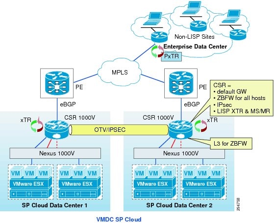
LISP and OTV roles can be deployed in the network, as shown in Figure 2-25. CSR 1000V within the VPC on source and destination data centers will be used as the OTV Edge device and LISP xTR. Mapping Server and Resolver will also reside on the CSR 1000V within the VPC at both the data centers in order to eliminate the use of additional devices and to reduce cost. This also improves scalability, as the MS/MR database will be per tenant. Figure 2-25 shows the options for proxy tunnel router (PxTR) deployment; the recommendation for PxTR deployment is on CSR1000V at the customer premise. Traffic to server VLANs, which are part of LISP domain, can be directed to the PxTR within the Enterprise.
Figure 2-25 LISP & OTV Roles and Deployment in Network
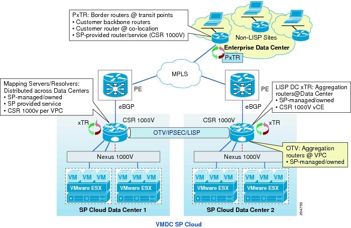
LISP Deployment Considerations
As an over-the-top technology, LISP has ingress (ITR) and egress (ETR) points. Everything that is in the core between these tunnel end points is overlaid transparently. The only strong requirement about this core is the ability to support greater PDU that includes the LISP header (Figure 2-26). The transport MTU should be 1536 to ensure transparency for 1500 bytes PDU. If the core is not able to accommodate a larger frame, then LISP ITR is able to support the Path MTU Discovery (PMTUD) approach. This sends the ICMP Destination Unreachable message (type 3, code 4) with a code meaning "fragmentation needed and DF set" back to the source of the packet as specified in the original IP header leading the source to adjust packet size to 1444. 1444 is the IP MTU of the original IP packet, but LISP also encapsulates the original IP header, so the payload of a LISP packet (before adding the external IP header) is: 1444 (original payload) + 20 (original Inner IP header) + 8 (LISP header) + 8 (UDP header) + 20 (Outer IP header) = 1500 bytes.
Figure 2-26 LISP Header Format
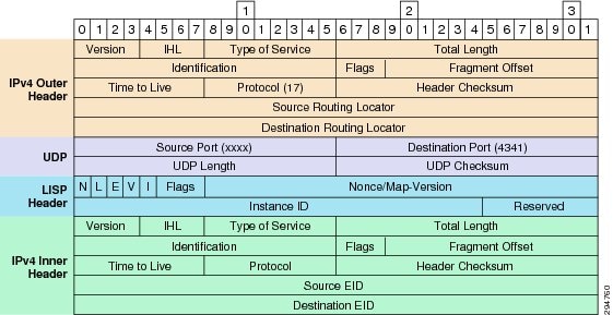
No other strict considerations are mandatory for the core transport. Other aspects like QoS may definitely be needed. In that aspect, LISP is copying the original DSCP towards its tunnel encapsulation header, allowing an end-to-end DiffServ behavior.
The two main LISP benefits to consider are multi-tenancy and mobility. LISP is a pervasive solution, and the placement of the xTR (ITR or ETR) can be seen in multiple places. The most ideal placement for an xTR would be on the CSR 1000V within the VMDC VSA 1.0 data centers. The default gateway resides in the data center and a dedicated CSR 1000V per tenant within the Cloud provides sufficient scalability. With this model, the Cloud would be fully virtualized in multiple instances and mobility across all data center sites. Some factors that add complexity to this simple model must be taken in consideration.
One of them, and probably the most complex, is the insertion of a firewalling service (Figure 2-27). No firewall currently on the market is able to read a LISP-encapsulated frame. This means that to be efficient the firewall must be placed "south" of the xTR in order to apply rules to a clear text traffic outside of any encapsulation. If the firewall is a virtual appliance or is a VSG running in the VM context, then there is no concern as the firewall service is south. If the firewall is running in transparent mode at the access layer, then again there is no concern as the firewall service is at the Layer 2 layer and is south of xTR. Within the VMDC VSA 1.0 architecture, CSR 1000v provides zone-based firewall capabilities. It will also be used as xTR. Firewall and LISP can coexist in this case improving the classical VMDC design with virtualization and mobility. Firewall and LISP can coexist, improving the classical VMDC design with virtualization and mobility. For this reason, multi-hop LISP is not required to support the DRaaS use case for failing over workloads from one VPC to another within the Cloud data centers.
Figure 2-27 LISP with Localized Firewall Services
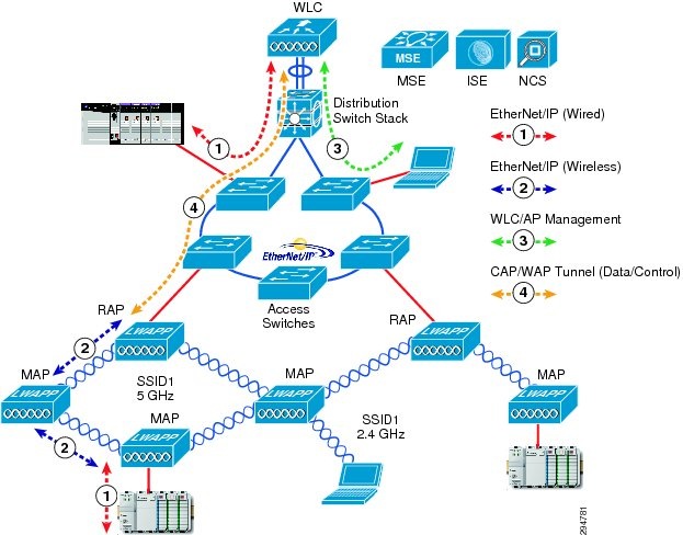
The other consideration is the LISP and SLB integration (Figure 2-28). Within the DRaaS Solution, the SLB Virtual IP (VIP) is active at one location at a time and represents the LISP EID. The failover of workloads belonging to the load-balanced server farm does not necessarily trigger a VIP move. For this reason, in the case of some servers within a server farm being failed over to the secondary site, they will still have the VIP located at the original site and the traffic flows from that site. In the case of all the servers within a server farm being failed over to a secondary site, the SLB VIP also has to be failed over to the secondary site to provide load-balancing services from the new site.
The failover of the VIP can be performed manually by touching the load-balancers deployed on both sites or to have the load-balancer as part of the virtual protection group along with the servers, which are part of the server farm. The idea is to failover all the servers along with the load balancer that are all contained within a protection group, from one site to another.
Our recommendation is to run the servers that are part of a load-balanced server farm from both primary and secondary sites in a unified fashion. The VIP location will be updated in LISP only when moved between the sites along with the servers that are load balanced.
Figure 2-28 LISP and SLB Integration
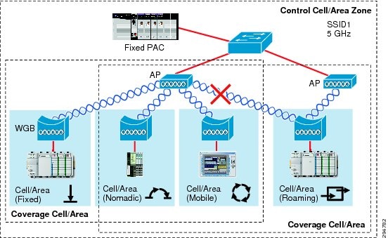
Available Replication Types
Figure 2-29 shows the different types of replication technologies that can be used for disaster recovery purposes.
Figure 2-29 DR Replication Technologies
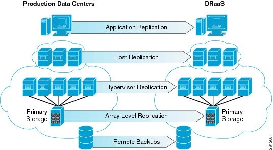
Storage Array Level Replication
The most popular replication method used by most of the organizations today is storage array-level replication. Array-based replication is expensive and lacks granularity. You need to purchase from a single storage vendor the exact type, brand, and model number of a storage array on both the source and target side of your DR solution. You need to budget for exactly the same storage class and tier. One of those storage arrays will stay dormant until a recovery situation requires it to be active.
An array-based solution typically replicates an entire volume even if there is only one VM in the volume that needs to be replicated. It does not provide the flexibility of replicating a single VM. It also requires multiple points of management while performing disaster recovery tasks and needs a separate runbook management tool along with the storage array management console.
Hypervisor-Based Replication
Hypervisor-based replication is a good option for organizations that have their entire environment virtualized. The agent that captures the changes on the production servers sits at the hypervisor layer. Since hypervisor-based replication is "VM-aware," it is possible to select the VMs that need to be replicated, while saving storage space at the secondary site by avoiding replicating the ones that do not.
Hypervisor-based replication allows you to be much more granular in what you protect, and it allows you to group VMs by defining protection groups. In addition, it can be managed from virtualization management suites like VMware's vCenter or Microsoft's System Center. Hypervisor-based replication is storage agnostic, which allows any-to-any storage replication. See Figure 2-30.
Figure 2-30 Hypervisor-Based Replication

Guest OS/Host-Based Replication
Many enterprises use host-based replication because it is relatively inexpensive. The process involves installing a replication agent onto the operating systems of the servers to be replicated. This agent processes and replicates I/O traffic on any storage systems (NAS, DAS, SAN, etc.) to a secondary replication target system, which use storage of any type, from any vendor.
It saves money compared to array-based replication because licensing host-based replication software is much less expensive than for most array-based replication systems. In addition, going to the expense of purchasing a second storage array that is identical to the primary one is unnecessary. SPs can deploy any storage type in their cloud while offering DRaaS. This allows them to offer DRaaS to customers using any storage and infrastructure.
Figure 2-31 shows OS/Host-based replication in the DRaaS Solution.
Figure 2-31 OS/Host-Based Replication
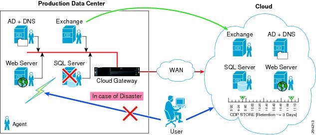
The DRaaS Solution uses both hypervisor-based replication and host-based replication for its simplicity and for providing greater coverage of protecting physical and virtual environments.
Zerto Virtual Replication
Zerto Virtual Replication (ZVR) and workflow orchestration is a powerful DR solution for organizations that have virtualized environments. ZVR functions at the hypervisor layer and replicates the changes made on the servers at the production site to one or more recovery locations, including cloud service provider sites. ZVR provides robust workflow orchestration of the failover, migration, and failback operations while allowing complete failover testing that is not disruptive to the production environment. For the CSP, ZVR is an important technological advance that opens up a entire new set of DRaaS and in the cloud cost-effective service offerings.
Since ZVR is "VM-aware," it is possible to select only the VMs that need protected, while saving storage space and bandwidth at the secondary site. However, ZVR does not require similar storage between sites, so not needing the same storage at the target site allows for the use of cheaper or repurposed storage. The CSP site can be added as a target site as well since ZVR has no hardware dependencies. This presents a compelling option to the customer for using one solution for protecting all of their servers, including lower-tier virtual machines to any site, public or private.
As a CSP, having the same data protection platform that the customer is using simplifies and accelerates the sales and on-boarding process, thus removing at least one barrier to adoption. Additionally, ZVR is natively multi-tenant, so the internal deployment into the CSP infrastructure is non-disruptive.
ZVR allows for very granular protection since the VMware virtual machine VMDKs are being replicated. For application protection, multiple VMs can be put into application-affinity groupings called Virtual Protection Groups (VPGs) Virtual machines that are in a VPG have write-order fidelity, which means that the recovery points-in-time are consistent across all the VMs in the VPG for consistent recoveries. ZVR has quickly become the de facto standard behind the most successful DRaaS and ICDR solutions because of the industry-changing approach to disaster recovery. A hypervisor-based replication solution aligns with the capabilities of the hypervisor, and extends the flexibility, agility, and benefits of virtualization to BC/DR.
- Removes deployment barriers with a storage-agnostic solution that installs seamlessly into the existing infrastructure.
- Supports multiple VMware vSphere versions and mixed VMware licensing levels and VMware vCloud environments.
- Provides a centralized DR management solution, regardless of the VM placement.
- Is completely "virtual aware" so the customer can make changes to the production environment without affecting BC/DR processes.
- Enables hybrid cloud services. Virtual machine portability between private and public clouds is simple with very low recovery times when using ZVR.
- Provides the technical infrastructure for secure and segmented multi-tenant DR access
However, providing disaster recovery services is different from providing other cloud-based services:
- In a DRaaS scenario, the customer may manage and have complete control over the production data or the CSP may provide a partial or complete managed service. In either case, the CSP must ensure the availability of the data and adapt as the customer's infrastructure changes. See Figure 2-32.
Figure 2-32 Multi-Tenant Cloud Service Provider Offering DRaaS
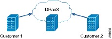
When customers leverage an ICDR service, the CSP manages the production and DR sites. The VMs are typically replicated from one CSP data center to another as a managed service or as managed co-located data centers. The customers have the ability to interact with their applications as if they were locally hosted. See Figure 2-33.
Figure 2-33 Inter-Cloud Disaster Recovery
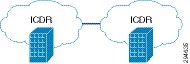
What is consistent in both scenarios is that the customers have deeper ties to their data when compared to other cloud-based services because they often need to access the actual virtual machines running the applications.
CSPs are challenged to provide a multi-tenant service that literally bridges together and connects dissimilar data centers from customers to their cloud as well as having customer-initiated tests and failovers.
Helping the CSP Provide a Dynamic DR Platform
At the core of the Zerto design philosophy is to simplify disaster recovery while providing powerful replication, recovery and testing with no impact on the environment.
ZVR makes VMs more geographically portable and simplifies the technology behind the DR that the CSP provides to customers. With ZVR 3.0, Zerto improves the management experience by adding multi-tenant cloud management and customer-initiated enablement technologies with Zerto Cloud Manager (ZCM) and the Zerto Self Service Portal (ZSSP).
The ZCM allows the CSP to provide resources from multiple CSP data centers and define service level templates called Service Profiles to multiple customers via a unified administrative interface. From the customer perspective, the CSP provides the ZSSP that is a web-based portal that enables self-initiated provisioning, testing and failover capability through a private, intuitive administration interface.
By making DR easier to provide and consume, Zerto helps the CSP reach the enterprise IT Manager better by offering DR options that were previously unfeasible or cost-prohibitive. The CSP can offer services ranging from fully managed DR to providing DR for only a portion of the enterprise's VMs where hybrid cloud-based DR approach is a better solution.
Figure 2-34 Workload Protection and Mobility
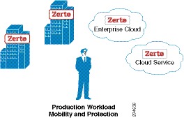
Enablement for Cloud DR Resource Management: Zerto Cloud Manager
CSPs regularly host the same customer in multiple global locations. ZVRs unique architecture can easily support replication between sites around the world.
While ZVR created an advantage for CSPs by enabling them to replicate to and from anywhere, it introduced the need for a centralized interface that consolidates information from multiple sites to make management and reporting easier and accurate.
Zerto has created the ZCM to deliver centralized management for DR in the cloud. The ZCM consolidates and streamlines resource information into a single interface to make multi-site, multi-tenant, dynamic DR environments easier to manage. The automated consolidation and reporting on cloud usage increases the confidence of customers that they are billed accurately on their infrastructure usage.
As shown in Figure 2-35, the ZCM manages all of the information from the ZVM at each location in a central user interface.
Figure 2-35 An Example ZVR Deployment
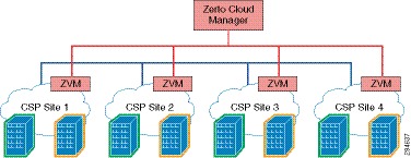
Enablement for Cloud DR Resource Consumption: Zerto Self Service Portal
DR requires an infrastructure level of integration between CSPs and customers. Depending on the service level requirements, cloud based DR presents a unique challenge for CSPs because it often requires a two-way interaction that most cloud providers are not prepared to provide.
When customers want a fully managed service, the CSP manages both sides of the DR as their own administrative resources can readily meet that need. However, when customers want a more interactive hybrid DR service that requires both CSP and the customer having infrastructure level administrative access, the CSP often has to create a customized DR portal to meet the customer access needs.
To help CSPs overcome the challenge of having to develop a custom portal just for DR, Zerto created the Zerto Self Service Portal (ZSSP). The ZSSP gives customers streamlined access to administrative functions and provides CSPs a way to deploy a complete cloud-based DR solution quickly.
The ZSSP is designed to be an out-of-the-box DR portal solution. Having a fully functioning browser-based service portal available without a great deal of coding or scripting enables CSPs to quickly introduce DR as part of their existing portal or as a stand-alone portal. CSPs are able to offer a robust DR service for faster ROI quickly. See Figure 2-36.
Figure 2-36 ZVM and the Zerto Self Service Portal
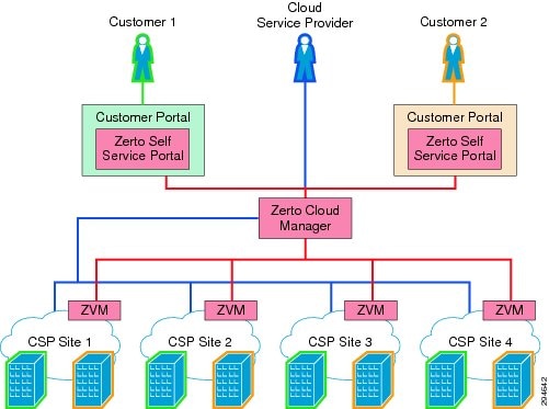
Being browser-based, the ZSSP enables unprecedented management of business continuity and disaster recovery. Administrators can monitor service levels; perform non-disruptive tests, and actual failovers from many different devices, including many mobile devices.
InMage ScoutCloud
InMage ScoutCloud Enables Recovery as a Service
The InMage ScoutCloud platform addresses the growing market for cloud-based disaster recovery products, also referred to as the Recovery as a Service (RaaS) market. InMage ScoutCloud leverages next generation recovery technologies including disk-based recovery, CDP, application snapshot API integration, asynchronous replication, application awareness, and WAN optimization. These next generation recovery technologies are wrapped up in a single product offering, enabling MSPs and cloud providers to have the fastest time-to-market when offering customers a near zero RPO and RTO- capable RaaS with:
- Best-in-class data protection.
- A comprehensive P2V and V2V recovery engine that supports all applications.
- A provisioning manager that automates provisioning of recovery for VMs and associated storage combined with a full-fledged multi-tenant portal.
Figure 2-37 shows the InMage ScoutCloud architecture in a DRaaS environment.
Figure 2-37 InMage ScoutCloud Architecture
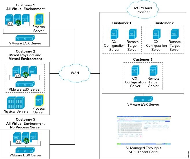
Continuous Data Protection (CDP): CDP refers to a technology that continuously captures or tracks data modifications by saving a copy of every change made to your data, essentially capturing every version of the data that you save. It allows you to restore data to any point in time. It captures the changes to data and sends them to a separate location. CDP-based solutions can provide fine granularities of restorable objects ranging from crash-consistent images to logical objects such as files, mailboxes, messages, and database files and logs.
Traditional backups require a schedule and restore data to the point at which it was backed up. CDP does not need a schedule because all the data changes on the primary server are tracked and sent to a secondary server asynchronously. Most CDP solutions save byte or block-level differences rather than file-level differences. This means that if you change one byte of a 100 GB file, only the changed byte or block is saved. CDP technology has the following fundamental attributes:
- Data changes of primary server are continuously captured or tracked.
- All data changes are stored in a separately located secondary server.
- It enables data recovery in much lesser time as compared to tape backup or archives.
Disaster Recovery (DR)—DR is the process of preparing for recovery or continuation of technology infrastructure critical to an organization after a natural or human-induced disaster. DR solution using CDP technology replicates your data to a separately located secondary server. In case of disaster, you can get immediate access to a primary server's data, which is up-to-the minute of disaster.
Application Protection Plan—An efficient Application Protection Plan can protect customer's critical applications from natural as well as human-interfered disaster. Every individual application of an organization should have a unique protection plan where the application can have single or multiple protections; i.e., the application can be protected locally for backup purpose or it can be protected to remote locations for DR purposes.
Replication Stages—InMage ScoutCloud replicates drive level data in three stages:
- Resyncing (Step I): In this step, data at the primary server is replicated to the secondary server. This is done only once for each drives that you want to replicate to a secondary server drive.
- Resyncing (Step II): All data changes during Resyncing (Step I) are replicated to the secondary server in this step.
- Differential Sync: Differential Sync is a continuous process where any change in the primary server volume is copied to the Secondary server volume simultaneously.
Consistent Data—In case of DR, the restored data should be consistent with the original data. To ensure the consistency of backup data, the consistent tags/bookmarks are issued at the primary server at periodic intervals of time or on demand.
Journal/Retention or CDP Logs—The retention or CDP logs store information about data changes on primary server within a specified time period on a separately located secondary server. This timeframe is referred to as the retention window. Consistent points are stored as bookmarks/tags in retention window. An application can be rolled back to one of the bookmarks/tags in this retention window. Alternately, an application can be rolled back to any point in time of this retention window. Applications that are rolled back to any of the bookmarks/tags in this retention window will only be consistent. Three types of retention policy are associated with this retention window:
- Time-based: The data in the retention window will be overwritten after the specified time period.
- Space-based: The data in the retention window will be overwritten once the size is exhausted.
- Time and space-based: The data in the retention window will be overwritten once the time specified or space specified qualifies first. ?
Sparse Retention—For long term data retention purposes, the sparse policy is used, which helps?to save disk space on retention volumes and makes it possible to afford a wider retention window. Depending on the type of policy enforced, the retention window is maintained by discarding older data changes within the retention log files to make rooms for new data changes. ?
- Failover: This is the process of switching production server to secondary server. The failover process can be a planned or an un-planned operation. The planned failover is used for periodic maintenance or software upgrades of primary servers wherein the data writes to primary server are stopped. An un- planned failover happens in case of actual failure of the primary server. ?
- Failback: This is the process of restoring the primary server from the secondary server after a planned or un-planned failover. A failover operation is usually followed by a failback operation. In this failback process, the data writes on the secondary server are also restored to the primary server. Scout also supports fast failback where the data changes of the secondary server are not applied to the primary server while restoring.
Snapshot—A snapshot is an exact replica of a primary server's data as it existed at a single point in time in retention window. The two types of snapshot are Physical Snapshot and Virtual Snapshot:
- For Physical Snapshot, you can take a snapshot on a physical volume. It requires the intended snapshot volume to be equal or larger than the Secondary server volume (in the replication pair).
- For Virtual Snapshot, you can take a snapshot on a virtual volume. It is also known as "vsnap," which requires minimal system resources and are faster in loading or unloading. These snapshots can be accessed in one of following modes:
–![]() Read-Only: As the name indicates, read only snapshots are for informative purposes and are not capable of retaining writes on to them.
Read-Only: As the name indicates, read only snapshots are for informative purposes and are not capable of retaining writes on to them.
–![]() Read-Write: Read/write virtual snapshots retain writes on to them; this is done by maintaining an archive log on some part of the local disk as specified.
Read-Write: Read/write virtual snapshots retain writes on to them; this is done by maintaining an archive log on some part of the local disk as specified.
–![]() Read-Write Tracking: Read/write tracking virtual snapshots goes a step forward; this is especially useful if a new virtual snapshot has to be updated with the writes of an un- mounted virtual snapshot.
Read-Write Tracking: Read/write tracking virtual snapshots goes a step forward; this is especially useful if a new virtual snapshot has to be updated with the writes of an un- mounted virtual snapshot.
Application Consistency—Application Consistency ensures the usability of the application when DR copies of the application's primary server data are used in place of the original data. An application can be rolled back to any bookmark/tag in the retention window. Consistency bookmarks are of the following three types:
- Application bookmarks: This bookmark ensures consistency at the application level. This is issued after flushing the application buffers to the disk.
- File System bookmarks: This bookmark ensures consistency of the data at the file system level. This is issued after flushing the file system cache to the disk.
- User-defined bookmarks: This is a user-defined name for a bookmark, which is associated with application bookmark or a file system bookmark or both. These are human readable bookmarks unlike the application or file system bookmarks, which are used by the DR administrators to recover the data.
- Scout CX Server—An appliance that performs the data movement between primary and secondary servers. It offloads various CPU intensive tasks from primary server, such as bandwidth management, caching, compression. It is also used to monitor protection plans by the vContinuum wizard.
- Master Target VM—A dedicated VM created on secondary vSphere server to act as a target for replication is called Master Target (MT). It is used as a target for replicating disks from primary VMs and master target contains the retention (CDP) data. To perform failback protection and failback recovery a Master Target VM is required on the primary Sphere server. In case of failback, replication is set in reverse direction from recovered secondary VMs back to Master Target on the primary vSphere server
- Management Console/GUI Wizard—A Windows 32 bit based GUI wizard that will walk through the protection and recovery steps. In case of Windows CX, it is installed along with the CX server. In case of Linux CX, wizard has to be installed on Windows 2008 R2, Windows7, XP or Vista desktop. vContinuum wizard can be installed on Master target in case of Windows.
- Unified Agent—Unified Agent is a lightweight agent that is installed on to each virtual machine or Physical server. It offloads the data changes to the CX appliance. The vContinuum wizard installs the Unified Agent automatically.
Enablement for Cloud Self-Service DR: InMage RX Portal
RX is the multi-tenant portal (see Figure 2-38) that enables the management of all customer services through a single portal and provides:
- Centralized monitoring across all customers.
- Fully re-brandable ready to use customer-facing dashboard.
- A full-fledged API stack for deeper integration into partner portals.
- Replication health and statistics for each CS server.
- License statistics for each CS server.
- Alerts and notifications.
- Provision to create logical groups for multiple CS servers to enforce policies on multiple CS servers in one shot.
- Custom reports on bandwidth usage for each CS server.
Figure 2-38 RX: Multi-Tenant Portal
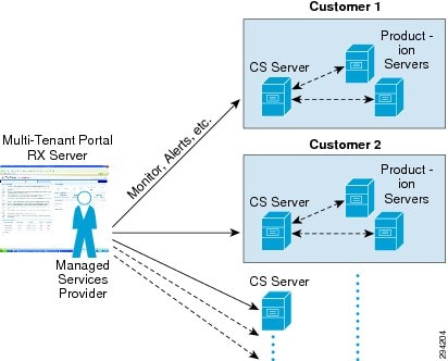
DRaaS Operational Workflows
Following are the workflows for protecting and recovering the customer's production workloads into the cloud. The workflows describe the process of creating the network containers for customers within the SP cloud, replication of workloads into the network containers, and recovery of workloads in the event of a disaster.
The workflow in Figure 2-39 is used for protection and failover scenarios.
Figure 2-39 New Customer Protection Workflow
Step 1![]() Based on the customer requirements, deploy a VMDC Network Container.
Based on the customer requirements, deploy a VMDC Network Container.
Step 2![]() Layer 2 extension and Secure IPsec connectivity is manually set up between the Enterprise and the VMDC-based cloud provider setup.
Layer 2 extension and Secure IPsec connectivity is manually set up between the Enterprise and the VMDC-based cloud provider setup.
Step 3![]() At both enterprise and service provider data centers, deploy and configure the necessary DR components
At both enterprise and service provider data centers, deploy and configure the necessary DR components
Step 4![]() Using DR tools, select the machines to be protected and set up the recovery plans. With properly configured network and compute components, the customers' servers should then be protected.
Using DR tools, select the machines to be protected and set up the recovery plans. With properly configured network and compute components, the customers' servers should then be protected.
Step 5![]() Allow customers to monitor the status of DR and RPO/RTO utilizing the DRaaS portals.
Allow customers to monitor the status of DR and RPO/RTO utilizing the DRaaS portals.
The workflow in case of a failure scenario is shown in Figure 2-40.
Figure 2-40 Failure Scenario Workflow
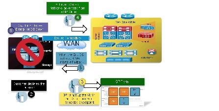
Step 1![]() When the customer data center goes down, customer declares a disaster and communicates to the service provider what VMs to restore and what checkpoints to use. The service provider can use the recovery plan, which could be preconfigured. This details the list of protected VMs, the startup order, and any custom steps, if required.
When the customer data center goes down, customer declares a disaster and communicates to the service provider what VMs to restore and what checkpoints to use. The service provider can use the recovery plan, which could be preconfigured. This details the list of protected VMs, the startup order, and any custom steps, if required.
Step 2![]() Service provider logs into the DRaaS portal and brings up the required VMs in the service provider environment. Customers with self-service capabilities will be able to recover VMs in the cloud themselves.
Service provider logs into the DRaaS portal and brings up the required VMs in the service provider environment. Customers with self-service capabilities will be able to recover VMs in the cloud themselves.
Step 3![]() Service provider advertises the networks from recovery site, which will allow the enterprise users to access recovered servers from the DR site.
Service provider advertises the networks from recovery site, which will allow the enterprise users to access recovered servers from the DR site.
Step 4![]() When the Enterprise data center is back up, the customer works with the service provider during a maintenance window to bring up the VMs in the customer data center and failback the VMs from the service provider to the enterprise. The client traffic is then re-routed to the customer data center.
When the Enterprise data center is back up, the customer works with the service provider during a maintenance window to bring up the VMs in the customer data center and failback the VMs from the service provider to the enterprise. The client traffic is then re-routed to the customer data center.
 Feedback