- Contents
- Topology
- Video (MPEG-4) Characteristics
- Media Server as a De-Jitter Buffer
- Packet Flow Between Camera and Media Server
- Reference Tests—Illustrate Loss versus Latency
- Typical Latency—Low Loss
- High Latency—No Loss
- LAN Latency—High Loss
- Implement Performance Routing to Address Packet Loss
- Summary
Performance Routing (PfR) Integration
Contents
This document shows that the video traffic flows from a video surveillance camera to the Media Server and then live or archived feed can be viewed through the Video Surveillance Operations Manager (VSOM) using a client viewing station. Viewing stations are workstations running Microsoft Internet Explorer (IE). Examples showing the impact of loss, latency, and jitter on the video feed are presented. Given an understanding of the requirements of the video surveillance traffic, a demonstration of how Performance Routing (PfR) is implemented on multiple WAN links to enhance the video quality. PfR intelligently selects the best WAN link, or a link that meets the configured criteria, from the available paths. Because video surveillance images often have a forensic use for identifying or criminally prosecuting subjects, optimal video quality is imperative for IP Video Surveillance deployments.
Topology
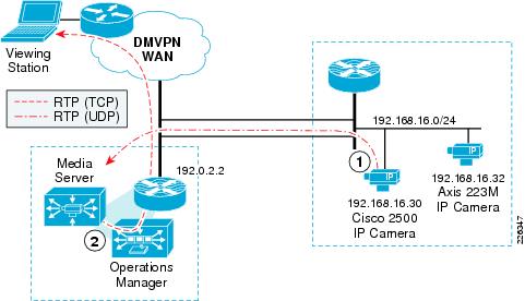
To illustrate how latency, loss, and jitter effect video feeds, we have set up a topology where the originating video feeds are not directly attached to the LAN of the Media Server recording the video. This allows test tools to introduce impairments in the network. The IP cameras are attached to a VLAN on a separate router from the branch location where the Video Management and Storage System (VMSS) network module resides. A WAN is simulated by injecting latency, loss, and jitter by a test appliance connected to two VLANs separating these locations. The branch router is a Cisco 2851 ISR with a NME-VMSS-16 network module. This topology is shown in Figure 1.
Figure 1 Performance Routing Test Topology

The PfR Master Controller and Border Router function are configured on the Cisco 2851 (IOS Release 12.4(15)T5) as well as the Cisco 7200 Series router at the campus location. The Cisco IP camera is Firmware Version is 1.1.1.
Video (MPEG-4) Characteristics
Before configuring PfR to select the best link, or a link that meets the minimum service level, we must first examine how the video in this example is encoded and transported between the camera and the Media Server. Most IP Video Surveillance cameras support Motion JPEG and MPEG-4. MPEG-4 usually refers to MPEG-4 part 2 encoding. Some cameras also support H.264, which is the nomenclature for MPEG-4 Part 10 or the Advanced Video Coding (AVC). The biggest difference between MPEG-4 part 2 and MPEG-4 Part 10 is the efficiency of the video compression.
MPEG-4 encoding is object-oriented compression, meaning it detects "objects" in the frame and sends out information when there is a change. A complete frame is sent to resynchronize periodically. This is called a key frame (slice) referred to as an I-frame. Predicted frames (P or B) build upon a reference slice. Usually, the key frame requires more than one IP packet for transport. In testing up to 30 IP packets have been observed to transport a single I-frame. Predicted frames may fit in a single IP packet but usually require more than one. MPEG-4 is typically encapsulated in UDP/RTP and is connectionless. The RTP header includes a packet sequence number so that the receiver can identify if packets are lost, but due to the connectionless nature of UDP, there is no retransmission of lost packets. When viewing the video feed with 1 percent or more loss, most people find the image noticeably degraded for standard definition images.
The Cisco 2500 Series IP camera uses UDP/RTP transport for video feeds to the Media Server. For IP cameras which MJPEG is supported, as is the case with the Axis 223M, the video feed between camera and Media Server is TCP-based. When viewing a live or archived video feed from a viewing station logged on VSOM, both MPEG-4 and MJPEG images are encapsulated in TCP/HTTP.
In this section PfR is used to optimize the UDP/RTP packets between camera and media server. In a later section, Wide Area Application Services (WAAS) is incorporated into the topology and both PfR and WAAS is used to optimize video feeds transported in TCP.
Media Server as a De-Jitter Buffer
In a Video Surveillance Manager (VSM) implementation, video from a surveillance camera is not viewed directly by a viewing station off the IP camera. Rather, the viewing station, a PC, connects to the web server of the Video Surveillance Operations Manager (VSOM). VSOM communicates with the Media Server and displays a video feed from the selected camera. If there is no active feed from the camera, the Media Server contacts the camera and initiates a live feed. The viewing station can display both live and archived feeds from one or more cameras defined to the Media Server.
Because camera feeds are not viewed directly from the camera, the Media Server acts as a de-jitter buffer for MPEG4-based video. This process is shown in Figure 2.
Figure 2 Video Path from Camera to Viewing Station
In general, packet loss presents more of an impairment to video quality than latency and jitter in this RTP/UDP deployment topology.
In VoIP deployments, latency impacts usability. As latency increases, the likelihood that two people would talk at the same time increases. This is referred to as the Walkie-talkie effect. Latency does not impact audio fidelity, it impacts usability. In VoIP, excessive jitter may be addressed by the de-jitter buffer in the IP telephone, but in some instances packets with excessive jitter are dropped if they arrive too late and must be dropped. Single packet loss for VoIP may not be noticed by the listener if packet loss concealment is implemented.
Video requirements differ from VoIP deployments in that surveillance applications have no two-way, real-time exchange of data. If the surveillance camera is a fixed camera, no Pan-Tilt-Zoom functions, the only two-way communication is the authentication step and RTSP step to initiate a camera feed. While latency in the network will slow down these packet flows, once the camera is initiating the RTP stream, no two-way communication is necessary. This packet flow between Media Server and IP Camera is described in more detail in the next section.
Loss for MPEG-4, however, cannot be recovered. There is no retransmission of lost packets. If the packet loss occurs in a `key slice', and this slice required 30 IP packets for transmission, this single packet loss causes the `key slice' to be incomplete. Packet loss degrades the MPEG-4 video quality.
The network characteristics to provide good video quality is different and, in some cases, more stringent than for VoIP. In general, VoIP is more tolerant to packet loss than video, while video is more forgiving to latency and jitter than VoIP.
Packet Flow Between Camera and Media Server
To better the network requirements for IP Video Surveillance, it is helpful to understand the process flow between a Cisco 2500 Series IP camera configured for MPEG-4 and the Media Server. In the authentication phase, the Media Server contacts the Cisco IP Camera with Hypertext Transfer Protocol over Secure Socket Layer (HTTPS - TCP port 443). This process takes approximately 2.5 seconds with 40 IP packets between the camera and Media Server. Next, the Media Server contacts the camera over the Real Time Streaming Protocol (RTSP - TCP port 554) to issue instructions to describe, setup, and play the video media stream. This requires approximately 12 packets over the period of 370ms. The IP camera then, begins to unicast the media stream (video feed) as Real-Time Transport Protocol (RTP - UDP port varies) packets. The RTP data is to be carried on an even UDP port number and the corresponding Real-time Transport Control Protocol (RTCP) packets are to be carried on the next higher (odd) port number. RTCP is not implemented on the Cisco IP Camera at this time.
The video feed continues until the Media Server instructs the camera to stop the media stream again through RTSP commands. This exchange is shown in Figure 3.
Figure 3 Packet Flow Between Camera and Media Server
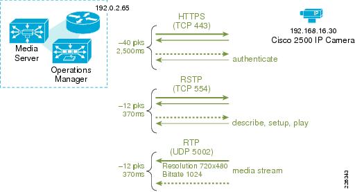
In this test, the camera has a resolution of 720x480 (D1) with a target bit-rate of 1024Kbps. The resulting RTP stream is observed at approximately 115 packets per second with an average of 1,054 bytes per packet.

Warning ![]() The Cisco IP camera can be configured to set the DSCP value of the RTP stream. However, the HTTPS or RTSP stream is not configurable and, unless set by a router or switch, is DSCP best effort.
The Cisco IP camera can be configured to set the DSCP value of the RTP stream. However, the HTTPS or RTSP stream is not configurable and, unless set by a router or switch, is DSCP best effort.
Reference Tests—Illustrate Loss versus Latency
Before configuring PfR to demonstrate how this feature can select and use one WAN link over another, we must first understand what impairment has the biggest impact on video quality. Once the application requirements are understood, PfR can be configured to manage the WAN links to optimize the application performance.
In the previous section, it was asserted that the quality of the video feed is degraded by packet loss more than latency. To illustrate this point, three tests were run and the video images are subjectively analyzed.
The Cisco IP Video Surveillance camera used in testing was configured with the following parameters:
Camera Name: CIVS-IPC-2500 ESELAB
Description: 001DE5EA7999
Camera Type: Cisco 2500 IP Camera
Server: VSMS_Site130
Host IP/Name: 192.168.16.30
Resolution: 720 x 480
Format: NTSC
Media Type: MPEG-4
UDP: On (UDP)
Bitrate: 1024
Quality: 50
Between the camera and Media Server there are two WAN links. Before PfR is enabled on the routers, the link that is used by the camera feed is subject to latency (jitter is influenced by the randomness of latency applied) and loss. The topology of the test is shown in Figure 4.
Figure 4 Reference Tests - Loss versus Latency
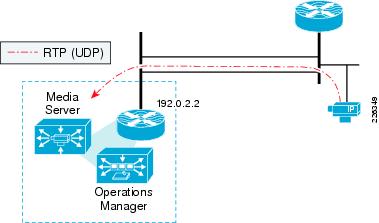
For each test, an archive is scheduled and retained for later viewing, with the WAN network simulator configured for the following criteria.
Typical Latency—Low Loss
•![]() Drop on-in 1,000 (1/10th 1%)
Drop on-in 1,000 (1/10th 1%)
•![]() Delay 30 to 40ms
Delay 30 to 40ms
High Latency—No Loss
•![]() Drop off (no configured packet loss)
Drop off (no configured packet loss)
•![]() Delay 120 to 150ms
Delay 120 to 150ms
LAN Latency—High Loss
•![]() Delay off (typical minimal LAN switching delay)
Delay off (typical minimal LAN switching delay)
•![]() Drop one-in 100 (1%)
Drop one-in 100 (1%)
The results of the three tests are described in the following sections.
Typical Latency—Low Loss
In this first test, latency was measured by an IP SLA probe traversing the same WAN link as the camera feed. The probe reported an average latency of approximately 35 milliseconds with jitter at 3ms. The MOS score is 4.06. Latency was applied in both directions, with a result of a round trip time (RTT) of approximately 71ms on average. Latency values in this range are not uncommon, for example, between two locations in North America serviced by Internet T1 links.
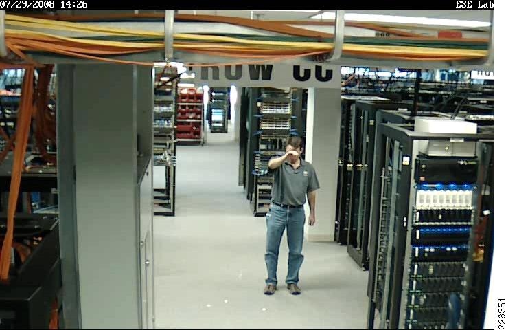
A snapshot from the video archive is shown in Figure 5.
Figure 5 Snapshot of Typical Latency—Low Loss Archive
The motion in the view of the camera is generally smooth. The subject is dropping packing peanuts in a lab environment with racks of network equipment, allowing the fan exhaust to blow the peanuts across the floor. Several peanuts are on the floor and to the left of the right knee of the subject, you can see several peanuts falling.
There are some artifacts with quick motion, but they are not excessive. This is used as a baseline to determine the difference in quality for the remaining tests.
A copy of this archive can be viewed at http://tools.cisco.com/cmn/jsp/index.jsp?id=84464
High Latency—No Loss
In this test, latency and jitter were increased. The IP SLA measured latency averaged 274ms RTT with one-way latency in the 135ms to 139ms range. Jitter averaged between 9 to 10ms with a maximum value of 25ms. The MOS score reported as 3.88. This latency is typical of links with high serialization delay such as dialup Internet connections, or with high propagation delay such as intercontinental Frame-Relay communications.
A snapshot from the archive is shown in Figure 6.
Figure 6 Snapshot of High Latency - No Loss Archive
The image quality is very similar to the baseline test. Motion is smooth. There is the same degree of video artifacts as the baseline test; artifacts are apparent when quick motion changes a large number of pixels. However, latency in the 150ms range (one-way) does not produce substantially different video quality than the baseline test.
A copy of this archive can be viewed at http://tools.cisco.com/cmn/jsp/index.jsp?id=84463
LAN Latency—High Loss
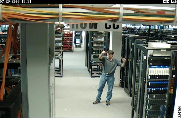
In this test, the artificially introduced delay was eliminated, but packet loss is 1 dropped packet in 100 packets, or 1 percent. The average RTT is only 2ms, or LAN like latency performance, but because of the packet loss, the IP SLA MOS score is 3.76. The network characteristics are the opposite of the previous test, but the packet loss introduced its own set of challenges for video. A snapshot from the archive is shown in Figure 7 with a white circle indicating the area of particular interest.
Figure 7 Snapshot of LAN Latency - High Loss Archive
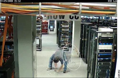
MPEG-4 has a high inter-frame dependency and artifacts become pronounced around 1 percent packet loss. In this archive, the artifacts are more pronounced than both the baseline and the previous test. They linger substantially longer. In many cases, the disruption of video quality is to such a degree that the subject is not identifiable.
The white circle overlay on the snapshot calls out an area of the image from which the subject has recently moved. His movement is from the right to left in the frame. What occurred in the video image is commonly called microblocking, tiling , mosaicking, or pixelating. These are terms used to describe a condition when the contents of a macroblock is missing or in error. Macroblocks are noticeable in an image as square-areas in the picture do not have complete information. The macroblock could be seen as a single color or a low-resolution block with noticeable edges.

Tip ![]() A macroblock represents a block of 16 by 16 pixels. The contents of the macroblock contains both luminance (brightness) and chroma (color) definitions.
A macroblock represents a block of 16 by 16 pixels. The contents of the macroblock contains both luminance (brightness) and chroma (color) definitions.
From this example, it is apparent that packet loss greatly impacts the video quality of this surveillance image. To address this, PfR is configured to select the path with packet loss as the primary differentiator between multiple links.
A copy of this video archive can be viewed at http://tools.cisco.com/cmn/jsp/index.jsp?id=84462
Implement Performance Routing to Address Packet Loss
There are two existing design guides that provide information on implementing performance routing in an enterprise network. These documents are available at the following URLs:
•![]() Transport Diversity: Performance Routing (PfR) Design Guide
Transport Diversity: Performance Routing (PfR) Design Guide
•![]() Performance Routing (PfR) Master Controller Redundancy Configuration
Performance Routing (PfR) Master Controller Redundancy Configuration
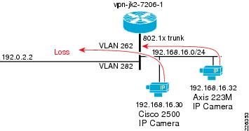
Topology
In the test topology, two links exist between the cameras and Media Server. These are FastEthernet links with a delay and loss generation tool configured to introduce 5 percent packet loss on the VLAN 262 (upper) link with a RTT of approximately 71ms. The second link, the lower link shown, has no loss but has the same 71ms round-trip delay. The MOS score of the link with the packet loss was 2.95 while the other link was 4.06. The topology is shown in Figure 8.
Figure 8 PfR Test Topology
Without PfR enabled, both links are in the IP routing table and Cisco Express Forwarding (CEF) load shares over the two links, based on source and destination IP address. In this example, both IP cameras are routed over the link with loss. This can be seen with the show ip cef exact-route command.
vpn-jk2-7206-1#show ip cef exact-route 192.168.16.30 192.0.2.2
192.168.16.30 -> 192.0.2.2 : FastEthernet0/1.262 (next hop 192.168.12.2)
vpn-jk2-7206-1#show ip cef exact-route 192.168.16.32 192.0.2.2
192.168.16.32 -> 192.0.2.2 : FastEthernet0/1.262 (next hop 192.168.12.2)
CEF does not take into consideration link characteristics. It uses a hash to determine which link is used for any one source and destination IP address pair. Based on the IP address of the source addresses, both cameras happen to use the same link. CEF can provide a degree of load sharing as the number of source/destination pairs increase, because statistically traffic will routed across both links. CEF can provide a degree of load sharing, but not load balancing. It has no mechanism to select an alternate path if the WAN performance is degraded due to latency or packet loss. At this point in the test, the OER master controller was administratively shutdown.
PfR Configuration
In this configuration, both master controller and the border router exist on the same router: the Cisco 7200 Series at the campus location. A similar configuration is implemented on the branch router. PfR has a requirement for at leas two external links (exit points) and one internal interface. These are shown configured under the border router section of the configuration.
Also a requirement of PfR, two equal cost routes, or parent routes, are included in the routing table. They are in the routing table from the two static routes defined in the configuration. In this example, they are default routes (0.0.0.0 / 0.0.0.0), but any equal cost route to the destination subnet is sufficient.
The destination network is explicitly identified by a prefix-list definition, as referenced in the oer-map named LOSS, which is invoked by the policy-rules command under the master controller definition. Learn mode is configured, but these statements apply to traffic observed in the NetFlow cache, traffic that is also on the network but not explicitly identified by the oer-map command.
The relevant configuration on the Cisco 7200 series router for PfR is shown below:
!
hostname vpn-jk2-7206-1
!
key chain PURPLE
key 10
key-string 7 xxxxxx
!
oer master
policy-rules LOSS
logging
!
border 192.168.16.1 key-chain PURPLE
interface FastEthernet0/1.282 external
interface FastEthernet0/1.262 external
interface FastEthernet0/1.216 internal
!
learn
throughput
delay
periodic-interval 0
monitor-period 1
expire after time 30
aggregation-type prefix-length 27
no max range receive
mode route control
mode select-exit best
!
!
oer border
local FastEthernet0/1.216
master 192.168.16.1 key-chain PURPLE
!
!
ip route 0.0.0.0 0.0.0.0 192.168.13.2 name OER_Parent
ip route 0.0.0.0 0.0.0.0 192.168.12.2 name OER_Parent
!
ip prefix-list SITE_130 seq 5 permit 192.0.2.0/27
!
oer-map LOSS 10
match traffic-class prefix-list SITE_130
set mode select-exit best
set mode route control
set mode monitor fast
set resolve loss priority 1 variance 10
set loss relative 100
set active-probe jitter 192.0.2.1 target-port 32000 codec g729a
set probe frequency 10
!
end
The oer-map command specifies that the `best' exit is used, and the monitor mode fast command is configured to provide for continuous probing of all exits at 10 seconds frequency. An explicitly configured active jitter probe is enabled using the G729a codec. The IP address target of the probe is the branch router VMSS network module logical interface IP address. On the branch router, the ip sla responder command must be configured so that the probes are replied to by the branch router.
Enabling PfR
In this test, the video feeds are active and being archived. PfR is enabled by entering configuration mode on the Cisco 7206 router at the campus location and initiating operation by issuing the no shutdown command to the master controller. This function is shown as follows:
vpn-jk2-7206-1(config-oer-mc)#no shut
vpn-jk2-7206-1(config-oer-mc)#
Aug 12 11:04:48.110 edt: %OER_MC-5-NOTICE: System enabled
Aug 12 11:04:51.870 edt: %OER_MC-5-NOTICE: BR 192.168.16.1 UP
...
Aug 12 11:04:52.062 edt: %OER_MC-5-NOTICE: Uncontrol Prefix 192.0.2.0/27, Traffi
c Class in Fast Mode
Aug 12 11:05:18.306 edt: %OER_MC-5-NOTICE: Route changed Prefix 192.0.2.0/27, BR
192.168.16.1, i/f Fa0/1.282, Reason None, OOP Reason Timer Expired
From the timestamps in the syslog messages, the elapsed time from the startup of operations to a point where PfR is managing the explicitly configured prefix is approximately 30 seconds. The exit chosen is the path with the least amount of packet loss. To view the current state of the network prefix, issue the show oer master prefix command. Sample output is shown below:
vpn-jk2-7206-1#show oer master prefix
OER Prefix Statistics:
Pas - Passive, Act - Active, S - Short term, L - Long term, Dly - Delay (ms),
P - Percentage below threshold, Jit - Jitter (ms),
MOS - Mean Opinion Score
Los - Packet Loss (packets-per-million), Un - Unreachable (flows-per-million),
E - Egress, I - Ingress, Bw - Bandwidth (kbps), N - Not applicable
U - unknown, * - uncontrolled, + - control more specific, @ - active probe all
# - Prefix monitor mode is Special, & - Blackholed Prefix
% - Force Next-Hop, ^ - Prefix is denied
Prefix State Time Curr BR CurrI/F Protocol
PasSDly PasLDly PasSUn PasLUn PasSLos PasLLos
ActSDly ActLDly ActSUn ActLUn EBw IBw
ActSJit ActPMOS ActSLos ActLLos
--------------------------------------------------------------------------------
192.0.2.0/27 HOLDDOWN @106 192.168.16.1 Fa0/1.282 STATIC
U U 0 0 0 0
72 72 0 0 723 1
3 0 0 0
In the output above, there are several items of interest. First, the prefix is in HOLDDOWN state. This is because the route for the prefix has recently changed. A prefix is placed in HOLDDOWN state to avoid link flapping and resulting destabilization of the network-wide routing tables. The exit bandwidth (EBw) and the input bandwidth (IBw) are shown. There is a great disparity between the two, although not unexpected. The traffic flow is from cameras to Media Server and very little traffic is destined for these cameras in this topology. Only control plane traffic would be sent to the cameras. The current exit interface (Fa0/1.282) is shown and this can also be verified by viewing the routing table. The short-term active delay and jitter is 72ms and 3ms, respectively.
Tip ![]() The show oer master prefix 192.0.2.0/27 detail command can be used to provide more verbose information on this prefix.
The show oer master prefix 192.0.2.0/27 detail command can be used to provide more verbose information on this prefix.
Effect on Video Quality
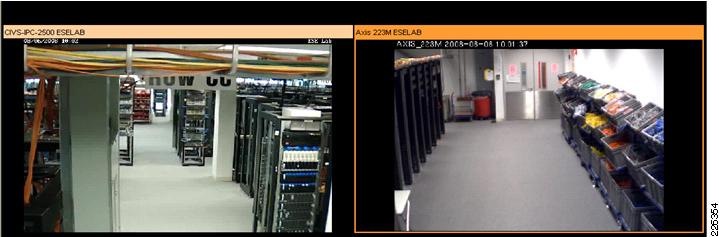
Previously, it was discussed how 1-percent packet loss can lead to noticeable degradation of the video image. In the test topology, the link that is the path of the video feeds when CEF is loadsharing over the two WAN link, has 5 percent loss. In the video archive, with this amount of loss, the faces of the people in the image are not recognizable, motion is very choppy, and artifacts clutter the video image and linger for long periods of time. The video does not clear up until a clean key slice is received to refresh the image. This amount of packet loss dramatically degrades the video quality.
When PfR is enabled and begins sending the video traffic over the link with no loss, immediately the video quality improves to what is normal for the camera. The snapshot in Figure 9 is the video images from both cameras after PfR has routed the traffic over the best link.
Figure 9 Video Images with Performance Routing Active
In a production network with two links between camera and Media Server, 5 percent packet loss is obviously an excessive amount of loss that should be identified by the enterprise network management system (NMS) function. The link with this excessive amount of loss must be taken out-of-service and corrected before being brought back online; however, PfR can circumvent the problem and take almost immediate action to preserve the quality of the video. PfR therefore is an important tool to address problems that may be a temporary disruption or need a short-term solution until a log-term fix can be implemented.
Summary
Packet loss dramatically degrades video quality. Constant or sustained packet loss at levels of 1 percent or more will decrease the usefulness of video images. Because of the forensic nature of IPVS, minimizing packet loss is critical to this video application. Loss can be attributed to hardware or soft failures that may not be identified by Layer-2 keepalives, static routes, or a Layer-3 Routing Protocol. When multiple links exist between the source of the video image and the storage system, PfR is an effective tool to select the best among several links between the video endpoints.
 Feedback