IP Video Surveillance Whitepapers
Bias-Free Language
The documentation set for this product strives to use bias-free language. For the purposes of this documentation set, bias-free is defined as language that does not imply discrimination based on age, disability, gender, racial identity, ethnic identity, sexual orientation, socioeconomic status, and intersectionality. Exceptions may be present in the documentation due to language that is hardcoded in the user interfaces of the product software, language used based on RFP documentation, or language that is used by a referenced third-party product. Learn more about how Cisco is using Inclusive Language.
- Updated:
- March 11, 2009
Chapter: Wide Area Application Services (WAAS) for iSCSI
Wide Area Application Services (WAAS) for iSCSI
Contents
The Cisco ISR router Video Management and Storage System (VMSS) network module houses an external Gigabit Ethernet interface on the module faceplate to provide connectivity to a locally attached Internet Small Computer System Interface (iSCSI) storage server. This iSCSI filesystem supplements the on-board disk drive for storing video archives. Cisco Video Management And Storage System (NME-VMSS-HP16/32 NME-VMSS-16) include GigE port for local iSCSI attachment. This is the preferred method and is described in the Local Storage for Video Archives Using iSCSI document.
While the recommended design is to archive locally, it is possible to route the iSCSI traffic through the ISR router backplane and the WAN interface(s) to reach a target IP address in the enterprise campus. Locating an iSCSI server in the campus and transporting archives across the WAN is of interest to customers for management and support efficiencies. Many customers, knowing the amount of bandwidth required to transport video feeds from surveillance cameras, have requested design guidance on what, if any, benefit implementing WAAS has on iSCSI transport of video archives over a WAN.
iSCSI Overview
The iSCSI operates over TCP port 3260 in this implementation. It does not require any dedicated cabling, it uses existing LAN switches and the IP network. iSCSI operates as a clear text protocol, there is no encryption inherent in the protcol. If it is transported over a public WAN or the nature of the video feeds require the need for data privacy, IPSec encryption must be deployed to meet that requirement. The TCP session between the NME-VMSS and iSCSI appliance is persistent, or long-lived. It is only terminated or initiated to recover from a timeout or manual shutdown.
Topology
The test topology is very similar to the topology used to test WAAS and PfR between branch and campus. The notable difference is the placement of the iSCSI appliance. Previously, it was attached to a LAN Gigabit Ethernet switch in the branch location. Now, it is connected to the LAN switch in the campus location. The IP address of the server has changed accordingly. There are four IP Video Surveillance cameras in the topology; an Axis 223M (MJPEG), Axis 207 (MPEG-4), Axis 207MW (MJPEG), and a Cisco 2500 series (MPEG4). Results are consistent across all cameras. The iSCSI server is a Buffalo (www.buffalotech.com) TeraStation Pro™ II iSCSI Rackmount Storage System. Figure 1 illustrates the topology.
Figure 1 WAAS and iSCSI Deployment Topology
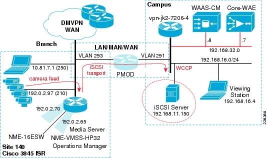
The path of the camera video feeds, iSCSI transport and location of the iSCSI server in the topology are shown for reference.
Configuration
The relevant portion of the branch router configuration is shown in this section. The WCCP configuration on the router is not changed from what was documented in the previous chapter. Because the iSCSI TCP session originates from the NME-VMSS-HP32 logical interface (Integrated-Service_Engine 3/0) the iSCSI TCP session is intercepted by WCCP configured on that interface.
!
hostname vpn1-3845-1
!
boot-start-marker
boot system flash
flash:c3845-adventerprisek9-mz.124-15.T5
!
!
interface GigabitEthernet0/1.210
description IP Camera VLAN
encapsulation dot1Q 210
ip address 192.0.2.97 255.255.255.224
!
!
interface Integrated-Service-Engine2/0
description NME-WAE-522-K9
ip address 192.0.2.69 255.255.255.252
ip wccp redirect exclude in
service-module ip address 192.0.2.70 255.255.255.252
service-module ip default-gateway 192.0.2.69
no keepalive
interface Integrated-Service-Engine3/0
description NME-VMSS-HP32
ip address 192.0.2.64 255.255.255.254
ip wccp 61 redirect in
ip wccp 62 redirect out
ip flow ingress
ip route-cache flow
! service-module external ip address 192.168.11.2 255.255.255.0
service-module ip address 192.0.2.65 255.255.255.254
service-module ip default-gateway 192.0.2.64
no keepalive
!
The external IP address which was in use as the iSCSI local subnet, 192.168.11.0/24, is commented out of the configuration.
The steps to move the iSCSI server from the branch to the campus is to:
Step 1 ![]() Deselect Media1_0 as disk from the Media Server.
Deselect Media1_0 as disk from the Media Server.
Step 2 ![]() Enter configuration mode of the VMSS network module and issue a `state disable' for Media1 to gracefully shutdown the service.
Enter configuration mode of the VMSS network module and issue a `state disable' for Media1 to gracefully shutdown the service.
Step 3 ![]() Shutdown the iSCSI service on the iSCSI server, change the IP address and physically move the connection to the correct VLAN at the campus and again enable the iSCSI service.
Shutdown the iSCSI service on the iSCSI server, change the IP address and physically move the connection to the correct VLAN at the campus and again enable the iSCSI service.
Step 4 ![]() Change the target IP address on the VMSS network module. Because the volume is already formatted, it will become available for use.
Change the target IP address on the VMSS network module. Because the volume is already formatted, it will become available for use.
Step 5 ![]() Select Media1_0 as a disk to be used by the Media Server.
Select Media1_0 as a disk to be used by the Media Server.
Following the above changes, the relevant portion of the VMSS network module configuration is shown as follows:
hostname VMSS-SITE140
storages iSCSI media1
target-ip 192.168.16.150
target-ip 192.168.16.150 volumeName iqn.2004-08.jp.buffalo:TS-RIGLB1E-001D7326
2B1E:array1 LUN 0
end storages-iscsi
end
Verification
To verify WAAS has selected the iSCSI TCP session for optimization, connection statistics for the remote WAE can be displayed with the show statistics connection command. Detailed output from the connection specific to the iSCSI TCP session is shown below:
vpn1-3845-1-WAE#show statistics connection conn-id 29275
Connection Id: 29275
Peer Id: 00:14:5e:85:54:7b
Connection Type: EXTERNAL CLIENT
Start Time: Fri Jan 9 10:23:56 2009
Source IP Address: 192.0.2.65
Source Port Number: 57326
Destination IP Address: 192.168.16.150
Destination Port Number: 3260
Application Name: Storage
Classifier Name: iSCSI
Map Name: basic
Directed Mode: FALSE
Configured Policy: TCP_OPTIMIZE + DRE + LZ
Derived Policy: TCP_OPTIMIZE + DRE + LZ
Peer Policy: TCP_OPTIMIZE + DRE + LZ
Negotiated Policy: TCP_OPTIMIZE + DRE + LZ
Accelerators: None

Note ![]() The above command was issued on Wed Jan 14 14:06:04 edt 2009 and the start time of the WAAS optimization is 9 January, demonstrating the persistence of the iSCSI TCP session.
The above command was issued on Wed Jan 14 14:06:04 edt 2009 and the start time of the WAAS optimization is 9 January, demonstrating the persistence of the iSCSI TCP session.
WAN Characteristics
In this test, the WAN link in use has a random delay averaging 60 milliseconds in each direction with packet loss of 1 packet per 10,000 packets.
Optimization Validation
In the previous section, the WAAS Effective WAN capacity report is used to demonstrate the bandwidth savings. In this section, NetFlow is used as a demonstration of another method of validating the WAN bandwidth savings. Understanding how NetFlow reports the flows prior to de-compression by the WAE as well as from WAE to the application server also provides a means of understanding how WAAS interception functions. In this test, a NetFlow export is configured on the campus router to a unix server. These Version 5 flows are captured and summarized.
The complete record layout for NetFlow Version 5 Flow Record Format is available on www.cisco.com. The SNMP index of the input and output interface is part of the flow record. In order to associate these Ifindex values with the interface name, the show snmp mib ifmib ifindex command is issued on the campus router and portions of the output are as follows:
vpn-jk2-7206-1# show snmp mib ifmib ifindex
FastEthernet0/0: Ifindex = 1
Null0: Ifindex = 6
...
FastEthernet0/1.232: Ifindex = 26
...
FastEthernet0/1.216: Ifindex = 25
FastEthernet0/1.291: Ifindex = 31
Both the WAAS compressed and optimized and the original flows are reported by NetFlow in the exported records. Because the source and destination IP address and port numbers are unchanged by WAAS, the Ifindex values are needed to identify the flows seen input from the WAN interface, and then the flow as it is observed following WCCP redirection.
NetFlow summarizes and reports the flow based on the source and destination IP address, port number, protocol, and ToS byte. The ECN bits are part of the ToS byte. The ECN field is bits 6 and 7 in the IPv4 ToS octet.
The layout of the ToS byte from RFC 3168 is as follows:
0 1 2 3 4 5 6 7
+-----+-----+-----+-----+-----+-----+-----+-----+
| DS FIELD, DSCP | ECN FIELD |
+-----+-----+-----+-----+-----+-----+-----+-----+
DSCP: differentiated services codepoint
ECN: Explicit Congestion Notification
WAAS sets the ECN bits and because NetFlow v5 reports all eight bites of the ToS byte, the flow observed from the WAN interface is reported as two flows; with and without the ECN bits set.
The Ifindex numbers displayed by the show snmp mib ifmib ifindex command are referenced on the topology as follows:
•![]() Ifindex 26 is VLAN 232—Core-WAE
Ifindex 26 is VLAN 232—Core-WAE
•![]() Ifindex 25 is VLAN 216—iSCSI Server
Ifindex 25 is VLAN 216—iSCSI Server
•![]() Ifindex 31 is VLAN 291—WAN
Ifindex 31 is VLAN 291—WAN
•![]() Ifindex 0 is the router chassis itself
Ifindex 0 is the router chassis itself
These are shown in Figure 2.
Figure 2 Ifindex to Interface Mapping

In testing, NetFlow v5 export is configured on the campus 7206 and summarized. The iSCSI traffic flows are extracted from the summarized data and presented in Table 1. A single archive of one camera, an Axis 207MW, is active during the data capture.
There is a single flow reported from the core WAE to the iSCSI server. This is the flow post WAE processing. From the WAN to the core WAE, there are two flows reported: one flow with a ToS byte of 0 another with a ToS byte value of 2. The ToS byte value of 2 flow are packets in the WAN traffic with the ECN field populated.
To compare the flows from the WAN to the core WAE and from the core WAE to the iSCSI server, we must add the total bytes from WAN to core WAE (839,682 + 240762778) for a combined value of 242,602,460 bytes. The number of bytes for the core WAE to the iSCSI server is 245,092,552. By comparing these two sets of values, the optimized verses the unoptimized traffic, the impact of WAAS compression on the flows is less than two percent.
As a point of comparison and verification, the Media Server provides the details of that same data when stored as an archive on the iSCSI disk. This output is shown as follows:
Archive History Details: 5MIN_207MW_only
Archive Name : a_p_Axis_207MW__192_0_2_98_-_a_5MIN_207MW_only
Storage Path : /media1_0/1000
Archive Type : regular
Video Width : 1280
Video Height : 720
Archive Status : SHELVED
Archive Media : jpeg
Recording Rate : 10.581754 Mbps
Video Quality : 50
Video Framerate : 30.000000 fps
Video Bitrate : 640
Archive Expiry : 5 days
Archive Size : 224512 Kbytes
Archive Start Time: Fri Jan 9 16:00:02 2009
Archive End Time : Fri Jan 9 16:04:46 2009
Max Fps : 13.482701
Max Frame Size : 103171 bytes
Archive Duration : 300 seconds
Current Duration : 284 seconds
Current Retention: 94.67%
This is a five-minute archive of a 1280 x 720 resolution Motion JPEG that on disk is 224,512 Kbytes. The NetFlow export includes IP Layer-3 overhead which accounts for the higher number of bytes reported by NetFlow.
Summary
Both Motion JPEG and MPEG4 or H.264 camera feeds are compressed by the encoding function of the IP Camera. Persistent Lempel-Ziv (LZ) compression can achieve compression ratios in the order of 2:1, 5:1 or even up to 100:1 if the data contains common strings of characters. LZ compression can be beneficial for data which has not been previously traversed the network and categorized by Data Redundancy Elimination (DRE). DRE maintains a database of data that has been observed on the network. DRE is application independent. DRE can eliminate up to 99 percent of redundant network traffic and provide up to 100:1 compression.
Because the files being transported and archived to the iSCSI server are solely video feeds, and this data has been compressed by the encoding function of the IP cameras, the iSCSI transport shows little bandwidth savings. However, WAAS can be very instrumental in compressing application data to free bandwidth for other uses, including network video traffic.
 Feedback