PE-to-CE Design Options
While the domain creating the MPLS L3 service consisting of P and PE routers remains the same regardless of access technologies, the technologies and designs used to connect the PE to CE device varies considerably based on technology preference, installed base, and operational expertise.
Common characteristics, however, exist for each of the options. Each design needs to consider the following:
- The topology implemented, either hub-and-spoke or rings
- How redundancy is configured
- The type of QoS implementation
Network availability is critical for enterprises because network outages often lead to loss of revenue. In order to improve network reliability, branch/Campus routers and data centers are multihomed on PE devices using one of the various access topologies to achieve PE node redundancy. Each topology should, however, be reliable and resilient to provide seamless connectivity. This is achieved as described in this chapter, which includes the following major topics:
Inter-Chassis Communication Protocol
PE nodes connecting to dual-homed CE work in active/standby model with active PE taking care of forwarding and standby PE monitoring the active PE status to take over forwarding in case of active PE failure. The nodes require a mechanism to communicate local connectivity failure to the CE and to detect peer node failure condition so that traffic can be moved to the standby PE. Inter-Chassis Communication Protocol (ICCP) provides the control channel to communicate this information.
ICCP allows active and standby PEs, connecting to dual-homed CPE, to exchange information regarding local link failure to CPE and detect peer node failure or its Core Isolation. This critical information helps to move forwarding from active to standby PE within milliseconds. PEs can be co-located or geo-redundant. ICCP communication between PEs occurs either using dedicated link between PEs or using the core network. ICCP configuration includes configuring redundancy group (RG) on both PEs with each other's address for ICCP communication. Using this information, PEs set up ICCP control connection and different applications like Multichassis Link Aggregation Group (MC-LAG) and Network Virtualization (nV) described in the next sections use this control connection to share state information. ICCP is configured as described below.
ICCP Configuration
Step 1![]() Add an ICCP redundancy group with the mentioned group-id.
Add an ICCP redundancy group with the mentioned group-id.
Step 2![]() This is the ICCP peer for this redundancy group. Only one neighbor can be configured per redundancy group. The IP address is the LDP router-ID of the neighbor. This configuration is required for ICCP to function.
This is the ICCP peer for this redundancy group. Only one neighbor can be configured per redundancy group. The IP address is the LDP router-ID of the neighbor. This configuration is required for ICCP to function.
Step 3![]() Configure ICCP backbone interfaces to detect isolation from the network core, and trigger switchover to the peer PE in case the core isolation is occurred on the active PE. Multiple backbone interfaces can be configured for each redundancy group. When all the backbone in-terfaces are not UP, this is an indication of core iso-lation.
Configure ICCP backbone interfaces to detect isolation from the network core, and trigger switchover to the peer PE in case the core isolation is occurred on the active PE. Multiple backbone interfaces can be configured for each redundancy group. When all the backbone in-terfaces are not UP, this is an indication of core iso-lation.
We discussed ICCP providing control channel between PEs to communicate state information to provide resilient access infrastructure which can be used by different topologies. The next section discusses various access topologies that can be implemented among branch, campus or data center devices, and the Enterprise L3VPN network. Each topology ensures redundancy and fast failure detection and convergence mechanisms to provide seamless last mile connectivity.
Ethernet Access
Ethernet access can be implemented in hub-and-spoke OR ring access as described below.
Hub-and-Spoke Using MC-LAG Active/Standby
In hub-and-spoke access topology, CE device is dual homed to PE devices in the MPLS VPN network. The MC-LAG feature provides an end-to-end interchassis redundancy solution for Enterprise. MC-LAG involves PE devices collaborating through ICCP connection to act as a single Link Aggregation Group (LAG) from the perspective of CE device, thus providing device-level and link-level redundancy. To achieve this, PE devices use ICCP connection to coordinate with each other to present a single LACP bundle (spanning the two devices) to the CE device. Only one of the PE devices forwards traffic at any one time, eliminating the risk of forwarding loops. L3VPN service is configured on this bundle interface or subinterface on PE. PE devices coordinate through the ICCP connection to perform a switchover while presenting an unchanged bundle interface to the CE for the following failure events:
- Link failure—A port or link between the CE and one of the PEs fails.
- Device failure—Meltdown or reload of one of the PEs, with total loss of connectivity to the CE, the core and the other PE.
- Core isolation—A PE loses its connectivity to the core network and therefore is of no value, being unable to forward traffic to or from the CE.
Figure 4-1 Figure X. Hub-and-Spoke Access with MLACP
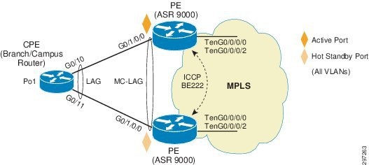
A loss of connectivity between the PEs may lead both devices to assume that the other has experienced device failure; this causes them to attempt to take on the active role, which causes a loop. CE can mitigate this situation by limiting the number of links so that only links connected to one PE are active at a time. Hub-and-spoke access configuration is described in Table 4-1 .
Table 4-2 describes CE configuration.
MC-LAG provides interchassis redundancy based on the active/standby PE model. In order to achieve the active/active PE model for both load balancing and redundancy, we can use VRRP as described below.
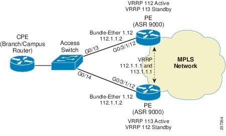
Hub-and-Spoke with VRRP IPv4 and IPv6 Active/Active
In hub-and-spoke access topology, the CE device is dual homed to PE devices in the MPLS VPN network. VRRP is used to provide VLAN-based redundancy and load balancing between PEs by configuring VRRP groups for multiple data VLANs on PEs. Each PE acts as a VRRP master for a set of VLANs. CE uses VRRP address as the default gateway. Half of the VLAN's traffic uses one VRRP master PE and the other half uses the other VRRP master PE. If any link or node fails on a PE, all traffic is switched to the other PE and it takes over the role of VRRP master for all the VLANs. This way both load balancing and redundancy between PEs is achieved using VRRP. BFD can be used to fast detect the VRRP peer failure. In order to detect core isolation, VRRP can be configured with backbone interface tracking so that if the backbone interface goes down, PE will decrease its VRRP priority and the peer PE will take master ownership for all the VLANs and switchover the traffic.
The branch /campus router CE is configured so that each of its uplinks to PEs is configured to forward all local VLANs. The data-path forwarding scheme causes the CE to automatically learn which PE or interface is active for a given VLAN. This learning occurs at an individual destination MAC address level.
Hub-and-spoke with VRRP configuration includes configuring bundle interface on both PE devices on the links connecting to the CE. In this case, although bundle interfaces are used, in contrast to MC-LAG, they are not aggregated across the two PEs. On PE ASR9000s, bundle subinterfaces are configured to match data VLANs, and VRF are configured on them for L3VPN service. VRRP is configured on these L3 interfaces. For achieving ECMP, one PE is configured with a higher priority for one VLAN VRRP group and the other PE for another VLAN VRRP group. VRRP hello timers can be changed and set to a minimum available value of 100msec. BFD is configured for VRRP for fast failover and recovery. For core isolation tracking, VRRP is configured with backbone interface tracking for each group so that if all backbone interfaces go down, the overall VRRP priority will be lowered below peer PE VRRP priority and the peer PE can take the master ownership.
Figure 4-2 Hub-and-Spoke Access with VRRP
PE Configuration
Step 1![]() Enter VRRP Configuration Mode.
Enter VRRP Configuration Mode.
Step 2![]() Enter bundle subinterface VRRP Configuration mode.
Enter bundle subinterface VRRP Configuration mode.
Step 3![]() Enter VRRP IPv4 address family for bundle subinterface.
Enter VRRP IPv4 address family for bundle subinterface.
Step 4![]() Configure VRRP group 112.
Configure VRRP group 112.
Step 5![]() Allow preemption to be delayed for a configurable time period, allowing the router to popu-late its routing table before becoming the active router.
Allow preemption to be delayed for a configurable time period, allowing the router to popu-late its routing table before becoming the active router.
Step 6![]() Configure VRRP address for the VRRP group.
Configure VRRP address for the VRRP group.
Step 7![]() Configure millisecond timers for advertisement with force keyword to force the timers.
Configure millisecond timers for advertisement with force keyword to force the timers.
Step 8![]() BFD enabled between PEs to detect fast failures.
BFD enabled between PEs to detect fast failures.
Step 9![]() Enable backbone tracking so that if one interface goes down, VRRP priority will be lowered by 100 and if two interfaces go down, (core isolation) priority will be lowered by 200; that will be lower than peer default priority and switchover will take place.
Enable backbone tracking so that if one interface goes down, VRRP priority will be lowered by 100 and if two interfaces go down, (core isolation) priority will be lowered by 200; that will be lower than peer default priority and switchover will take place.
Step 10![]() Enter VRRP IPv6 address family for bundle subinterface.
Enter VRRP IPv6 address family for bundle subinterface.
Step 11![]() Configure VRRP group 112.
Configure VRRP group 112.
Step 12![]() Make high priority for VRRP group 112 to 254 so that PE becomes VRRP active for this group.
Make high priority for VRRP group 112 to 254 so that PE becomes VRRP active for this group.
Step 13![]() Allow preemption to be delayed for a configurable time period, allowing the router to popu-late its routing table before becoming the active router.
Allow preemption to be delayed for a configurable time period, allowing the router to popu-late its routing table before becoming the active router.
Step 14![]() Configure VRRP address for the VRRP group.
Configure VRRP address for the VRRP group.
Step 15![]() Configure millisecond timers for advertisement with force keyword to force the timers.
Configure millisecond timers for advertisement with force keyword to force the timers.
Step 16![]() Enter Bundle subinterface VRRP Configuration Mode.
Enter Bundle subinterface VRRP Configuration Mode.
Step 17![]() Enter VRRP IPv4 address family for bundle subinterface.
Enter VRRP IPv4 address family for bundle subinterface.
Step 18![]() Configure VRRP group 113. Default priority for VRRP group 113 so that other PE with 254 priority becomes VRRP active for this group.
Configure VRRP group 113. Default priority for VRRP group 113 so that other PE with 254 priority becomes VRRP active for this group.
Step 19![]() Configure VRRP address for the VRRP group.
Configure VRRP address for the VRRP group.
Step 20![]() Configure millisecond timers for advertisement with force keyword to force the timers.
Configure millisecond timers for advertisement with force keyword to force the timers.
Step 21![]() BFD enabled between PEs tp detect fast failures.
BFD enabled between PEs tp detect fast failures.
Step 22![]() Enter VRRP IPv6 address family for bundle subinterface.
Enter VRRP IPv6 address family for bundle subinterface.
Step 23![]() Configure VRRP group 113. Default priority for VRRP group 113 so that other PE becomes VRRP active for this group.
Configure VRRP group 113. Default priority for VRRP group 113 so that other PE becomes VRRP active for this group.
Step 24![]() Configure VRRP address for the VRRP group.
Configure VRRP address for the VRRP group.
Step 25![]() Configure millisecond timers for advertisement with force keyword to force the timers.
Configure millisecond timers for advertisement with force keyword to force the timers.
Step 26![]() BFD enabled between PEs tp detect fast failures.
BFD enabled between PEs tp detect fast failures.
Step 27![]() Configure physical interface with Bundle.
Configure physical interface with Bundle.
Step 28![]() Configure VRF under interface for L3VPN service.
Configure VRF under interface for L3VPN service.
Step 29![]() Configure VRF under interface for L3VPN service.
Configure VRF under interface for L3VPN service.
Access switch is configured with data VLANs allowed on PE and CE-connecting interfaces. Spanning tree is disabled as Pseudo MLACP takes care of the loop prevention.
Access Switch Configuration
Step 1![]() Disable spanning tree for data VLANs used in Pseudo MLACP.
Disable spanning tree for data VLANs used in Pseudo MLACP.
Step 2![]() Trunk connecting to CE and PE has the same configuration allowing the data VLANs on trunks.
Trunk connecting to CE and PE has the same configuration allowing the data VLANs on trunks.
CPE Configuration
Step 3![]() IPv4 and IPv6 static routes configured with next hop as VRRP address. One PE is master for one VRRP address and the other PE is master for other VRRP address.
IPv4 and IPv6 static routes configured with next hop as VRRP address. One PE is master for one VRRP address and the other PE is master for other VRRP address.
G.8032 Ring Access with VRRP IPv4 and IPv6
In this access topology, PEs are connected to a G.8032 Ethernet ring formed by connecting Ethernet access nodes to each other in a ring form. The G.8032 Ethernet ring protection switching protocol elects a specific link to protect the entire ring from loops. Such a link, which is called the Ring Protection Link (RPL), is typically maintained in disabled state by the protocol to prevent loops. The device connecting to the RPL link is called the RPL owner responsible for blocking RPL link. Upon a node or a link failure in the ring, the RPL link is activated allowing forwarding to resume over the ring. G.8032 uses Ring Automatic Protection Switching (R-APS) messages to coordinate the activities of switching the RPL on and off using a specified VLAN for the APS channel.
The G.8032 protocol also allows superimposing multiple logical rings over the same physical topology by using different instances. Each instance contains an inclusion list of VLAN IDs and defines different RPL links. In this guide, we are using two G.8032 instances with odd-numbered and even-numbered VLANs. ASR9000's PEs also participate in the ring and act as the RPL owner. One PE acts as RPL owner for RPL for even-numbered VLAN's instance and the other PE as RPL owner for RPL for odd-numbered VLAN's instance so one PE remains in blocking state for one instance and other PE for other instance. Hence, load balancing and redundancy are achieved by making use of two RPLs, each RPL serving one instance.
In the G.8032 configuration, PE devices, which are configured as RPL owner nodes for one of the two instances, are specified with the interface connected to the ring. Two instances are configured for odd and even VLANs. PEs are configured as RPL owner for one of the instances each to achieve load balancing and redundancy. Both instances are configured with dot1q subinterface for the respective APS channel communication.
PEs are configured with BVI interfaces for VLANs in both instances and VRF is configured on BVI interfaces for L3VPN service. CE interface connecting to G.8032 ring is configured with trunk allowing all VLANs on it and SVIs configured on CE for L3 communication. BVIs are configured with First Hop Redundancy Protocol (FHRP) and CE uses FHRP address as default gateway. In our example, we are using VRRP on PEs as FHRP although we can use any available FHRP protocol. PEs are configured with high VRRP priority for VLANs in the case for which they are not RPL owner. CE uses VRRP address as default gateway. Since VRRP communication between PEs will be blocked along the ring due to G.8032 loop prevention mechanism, a pseudowire configured between PEs exists that enables VRRP communication. In normal condition, CE sends traffic directly along the ring to VRRP active PE gateway. Two failure conditions exist:
- In the case of link failure in ring, both PEs will open their RPL links for both instances and retain their VRRP states as VRRP communication between them is still up using pseudowire. Due to the broken ring, CE will have direct connectivity to only one PE along the ring, depending on which section (right or left) of G8032 ring has failed. In that case, CE connectivity to other PE will use the path to reachable PE along the ring and then use pseudowire between PEs.
- In the case of PE Node failure, pseudowire connectivity between PEs will go down causing VRRP communication to also go down. The PE that is UP to become VRRP Active for all VLANs and all traffic from CE will be sent to that PE.
Figure 4-3 Ethernet Access with G.8032 Ring
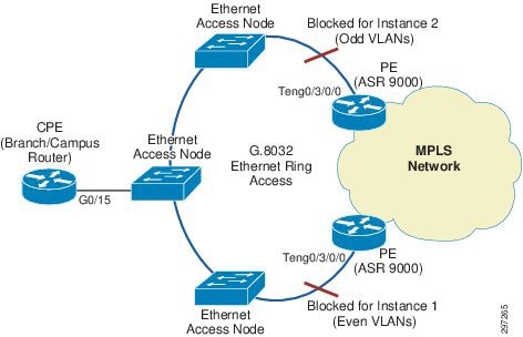
PE's dot-1q subinterface for data VLAN communication with CE, pseudowire connecting both PEs and BVI interface are configured in the same bridge domain, which allows both PEs and CE in same broadcast domain for that data VLAN. So if the link fails, the CE can still communicate to both PEs along the available path and pseudowire.
PE Configuration
Step 1![]() Interface connecting to G.8032 interface.
Interface connecting to G.8032 interface.
Step 2![]() Subinterface for data VLAN 118.
Subinterface for data VLAN 118.
Step 3![]() Subinterface for data VLAN 119.
Subinterface for data VLAN 119.
Step 4![]() Symmetrically POP 1 tag while receiving the packet and PUSH 1 tag while sending the traffic from interface.
Symmetrically POP 1 tag while receiving the packet and PUSH 1 tag while sending the traffic from interface.
Step 5![]() Interface BVI configuration mode.
Interface BVI configuration mode.
Step 6![]() Configuring VRF under interface.
Configuring VRF under interface.
Step 7![]() Interface BVI configuration mode.
Interface BVI configuration mode.
Step 8![]() Configuring VRF under interface.
Configuring VRF under interface.
Step 9![]() Enter VRRP Configuration Mode.
Enter VRRP Configuration Mode.
Step 10![]() Enter Bundle subinterface VRRP Configuration mode.
Enter Bundle subinterface VRRP Configuration mode.
Step 11![]() Enter VRRP IPv4 address family for bundle subinterface.
Enter VRRP IPv4 address family for bundle subinterface.
Step 12![]() Configure VRRP group 118.
Configure VRRP group 118.
Step 13![]() Make high priority for VRRP group 118 to 254 so that PE becomes VRRP active for this group.
Make high priority for VRRP group 118 to 254 so that PE becomes VRRP active for this group.
Step 14![]() Allow preemption to be delayed for a configurable time period, allowing the router to popu-late its routing table before becoming the active router.
Allow preemption to be delayed for a configurable time period, allowing the router to popu-late its routing table before becoming the active router.
Step 15![]() Configure VRRP address for the VRRP group.
Configure VRRP address for the VRRP group.
Step 16![]() Configure millisecond timers for advertisement with force keyword to force the timers.
Configure millisecond timers for advertisement with force keyword to force the timers.
Step 17![]() BFD enabled between PEs to detect fast failures.
BFD enabled between PEs to detect fast failures.
Step 18![]() Enter VRRP IPv6 address family for bundle subinterface.
Enter VRRP IPv6 address family for bundle subinterface.
Step 19![]() Configure VRRP group 118.
Configure VRRP group 118.
Step 20![]() Make high priority for VRRP group 118 to 254 so that PE becomes VRRP active for this group.
Make high priority for VRRP group 118 to 254 so that PE becomes VRRP active for this group.
Step 21![]() Allow preemption to be delayed for a configurable time period, allowing the router to popu-late its routing table before becoming the active router.
Allow preemption to be delayed for a configurable time period, allowing the router to popu-late its routing table before becoming the active router.
Step 22![]() Configure VRRP address for the VRRP group.
Configure VRRP address for the VRRP group.
Step 23![]() Configure millisecond timers for advertisement with force keyword to force the timers.
Configure millisecond timers for advertisement with force keyword to force the timers.
Step 24![]() Enter Bundle subinterface VRRP Configuration mode.
Enter Bundle subinterface VRRP Configuration mode.
Step 25![]() Enter VRRP IPv4 address family for bundle subinterface.
Enter VRRP IPv4 address family for bundle subinterface.
Step 26![]() Configure VRRP group 119. Default priority for VRRP group 119 such that other PE with 254 priority becomes VRRP active for this group.
Configure VRRP group 119. Default priority for VRRP group 119 such that other PE with 254 priority becomes VRRP active for this group.
Step 27![]() Configure VRRP address for the VRRP group.
Configure VRRP address for the VRRP group.
Step 28![]() Configure millisecond timers for advertisement with force keyword to force the timers.
Configure millisecond timers for advertisement with force keyword to force the timers.
Step 29![]() BFD enabled between PEs to detect fast failures.
BFD enabled between PEs to detect fast failures.
Step 30![]() Enter VRRP IPv6 address family for bundle subinterface.
Enter VRRP IPv6 address family for bundle subinterface.
Step 31![]() Configure VRRP group 113. Default priority for VRRP group 113 so that other PE becomes VRRP active for this group.
Configure VRRP group 113. Default priority for VRRP group 113 so that other PE becomes VRRP active for this group.
Step 32![]() Configure VRRP address for the VRRP group.
Configure VRRP address for the VRRP group.
Step 33![]() Configure millisecond timers for advertisement with force keyword to force the timers
Configure millisecond timers for advertisement with force keyword to force the timers
Step 34![]() Enter L2VPN Configuration mode.
Enter L2VPN Configuration mode.
Step 35![]() Configure bridge group named L2VPN.
Configure bridge group named L2VPN.
Step 36![]() Configure Bridge-domain named CE-L3VPN-118.
Configure Bridge-domain named CE-L3VPN-118.
Step 37![]() Enable subinterface connected to ring towards CE under bridge domain CE-L3VPN-118.
Enable subinterface connected to ring towards CE under bridge domain CE-L3VPN-118.
Step 38![]() Configure pseudowire to neighbor PE in the same bridge domain.
Configure pseudowire to neighbor PE in the same bridge domain.
Step 39![]() Configure L3 interface BVI in the same bridge domain CE-L3VPN-118.
Configure L3 interface BVI in the same bridge domain CE-L3VPN-118.
Step 40![]() Configure another bridge domain CE-L3VPN-119.
Configure another bridge domain CE-L3VPN-119.
Step 41![]() Enable subinterface connected to ring towards CE under same bridge domain CE-L3VPN-119.
Enable subinterface connected to ring towards CE under same bridge domain CE-L3VPN-119.
Step 42![]() Configure pseudowire to neighbor PE in the same bridge domain CE-L3VPN-119.
Configure pseudowire to neighbor PE in the same bridge domain CE-L3VPN-119.
Step 44![]() Configure G.8032 ring named ring_test.
Configure G.8032 ring named ring_test.
Step 45![]() Configure port0 for g.8032 ring.
Configure port0 for g.8032 ring.
Step 46![]() Mention port 1 as none and G.8032 ring as open ring.
Mention port 1 as none and G.8032 ring as open ring.
Step 47![]() Enter instance 1 configuration.
Enter instance 1 configuration.
Step 48![]() Configure VLANs in the inclusion list of instance 1.
Configure VLANs in the inclusion list of instance 1.
Step 49![]() Enter APS channel configuration mode.
Enter APS channel configuration mode.
Step 50![]() Configure subinterface used for APS channel communication.
Configure subinterface used for APS channel communication.
Step 51![]() Enter instance 2 configuration.
Enter instance 2 configuration.
Step 52![]() Configure instance with ring profile.
Configure instance with ring profile.
Step 53![]() Configure PE as RPL owner on port0 for instance 2.
Configure PE as RPL owner on port0 for instance 2.
Step 54![]() Configure VLANs in the inclusion list of instance 1.
Configure VLANs in the inclusion list of instance 1.
Step 55![]() Enter APS channel configuration mode.
Enter APS channel configuration mode.
Step 56![]() Configure subinterface used for APS channel communication.
Configure subinterface used for APS channel communication.
Step 57![]() Configure Ethernet Ring profile.
Configure Ethernet Ring profile.
Step 58![]() Configure G.8032 WTR timer.
Configure G.8032 WTR timer.
Step 59![]() Configure Guard timer.
Configure Guard timer.
Step 60![]() Configure hold-off timer.
Configure hold-off timer.
CE Configuration
Step 1![]() Enable VKA 118 and 119.
Enable VKA 118 and 119.
Step 2![]() Configure data SVI on CE.
Configure data SVI on CE.
Step 3![]() Configure data SVI on CE.
Configure data SVI on CE.
Step 4![]() Enable G.8032 ring facing trunk to allow data VLANs.
Enable G.8032 ring facing trunk to allow data VLANs.
Step 5![]() Configure IPv4 Static route towards VRRP address for VLAN 118.
Configure IPv4 Static route towards VRRP address for VLAN 118.
Step 6![]() Configure IPv4 Static route towards VRRP address for VLAN 119.
Configure IPv4 Static route towards VRRP address for VLAN 119.
Step 7![]() Configure IPv6 Static route towards VRRP address for VLAN 118.
Configure IPv6 Static route towards VRRP address for VLAN 118.
Step 8![]() Configure IPv6 Static route towards VRRP address for VLAN 119.
Configure IPv6 Static route towards VRRP address for VLAN 119.
Ethernet Access Node Configuration
Step 1![]() Configure Ethernet Ring profile.
Configure Ethernet Ring profile.
Step 2![]() Configures G.8032 WTR timer.
Configures G.8032 WTR timer.
Step 4![]() Configure G.8032 ring named ring_test.
Configure G.8032 ring named ring_test.
Step 5![]() Configures ring as G.8032 ring as open ring.
Configures ring as G.8032 ring as open ring.
Step 7![]() Mention port0 as ten 0/0/0/0 for ring.
Mention port0 as ten 0/0/0/0 for ring.
Step 8![]() Mention port1 as ten 0/0/0/0 for ring
Mention port1 as ten 0/0/0/0 for ring
Step 10![]() Configure instance with ring profile.
Configure instance with ring profile.
Step 11![]() Configure VLANs included in Instance 1.
Configure VLANs included in Instance 1.
Step 12![]() Configure APS channel.
Configure APS channel.
Step 13![]() Assign service instance for APS messages on port0 and Port 1.
Assign service instance for APS messages on port0 and Port 1.
Step 15![]() Configure instance with ring profile.
Configure instance with ring profile.
Step 16![]() Configure device interface as next neighbor to RPL link owner.
Configure device interface as next neighbor to RPL link owner.
Step 17![]() Configure VLANs included in Instance 2.
Configure VLANs included in Instance 2.
Step 18![]() Configure APS channel.
Configure APS channel.
Step 19![]() Assign service instance for APS messages on port0 and Port 1.
Assign service instance for APS messages on port0 and Port 1.
Step 20![]() Configure interface connected to ring.
Configure interface connected to ring.
Step 21![]() Configure service instance used for APS messages on G.8032 ring for both instances.
Configure service instance used for APS messages on G.8032 ring for both instances.
Step 22![]() Configure interface connected to ring.
Configure interface connected to ring.
Step 23![]() Configure service instance used for APS messages on G.8032 ring for both instances.
Configure service instance used for APS messages on G.8032 ring for both instances.
nV (Network Virtualization) Access
nV Satellite enables a system-wide solution in which one or more remotely-located devices or "satellites" complement a pair of host PE devices to collectively realize a single virtual switching entity in which the satellites act under the management and control of the host PE devices. Satellites and Hosts PEs communicate using a Cisco proprietary protocol that offers discovery and remote management functions, thus turning the satellites from standalone devices into distributed logical line cards of the host.
The technology, therefore, allows Enterprises to virtualize access devices to which branch or campus the routers terminate, converting them into nV Satellite devices, and to manage them through PE nodes that operate as nV hosts. By doing so, the access devices transform from standalone devices with separate management and control planes into low profile devices that simply move user traffic from a port connecting branch or campus router towards a virtual counterpart at the host, where all network control plane protocols and advanced features are applied. The satellite only provides simple functions such as local connectivity and limited (and optional) local intelligence that includes ingress QoS, OAM, performance measurements, and timing synchronization.
The satellites and the hosts exchange data and control traffic over point-to-point virtual connections known as Fabric Links. Branch or Campus Ethernet traffic carried over the fabric links is specially encapsulated using 802.1ah. A per-Satellite-Access-Port derived ISID value is used to map a given satellite node physical port to its virtual counterpart at the host for traffic flowing in the upstream and downstream direction. Satellite access ports are mapped as local ports at the host using the following naming convention:
<port type><Satellite-ID>/<satellite-slot>/<satellite-bay>/<satellite-port>
- <port type> is GigabitEthernet for all existing satellite models
- <Satellite-ID> is the satellite number as defined at the Host
- <satellite-slot>/<satellite-bay>/<satellite-port> are the access port information as known at the satellite node.
These satellite virtual interfaces on the Host PEs are configured with VRF to enable L3VPN service.
The satellite architecture encompasses multiple connectivity models between the host and the satellite nodes. The guide will discuss release support for:
In all nV access topologies, host nodes load share traffic on a per-satellite basis. The active/standby role of a host node for a specific satellite is determined by a locally-defined priority and negotiated between the hosts via ICCP.
ASR9000v and ASR901 are implemented as a satellite devices:
- ASR9000v has four 10 GbE ports that can be used as ICL.
- ASR901 has two GbE ports that can be used as ICL and that can be used as ICL and ASR903 can have up to two 10 GbE ports can be used as ICL.
nV Satellite Simple Rings
In this topology, satellite access nodes connecting branch or campus are connected in an open ring topology terminating at the PE host devices as shown in Figure 4-4.
Figure 4-4 nV with L1 Fabric Access
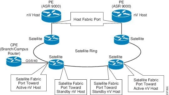
The PE device advertises multicast discovery messages periodically over a dedicated VLAN over fabric links. Each satellite access device in the ring listens for discovery messages on all its ports and dynamically detects the Fabric link port toward the host.
The satellite uses this auto-discovered port for the establishment of a management session and for the exchange of all the upstream and the downstream traffic with each of the hosts (data and control). At the host, incoming and outgoing traffic is associated to the corresponding satellite node using the satellite mac address, which was also dynamically learned during the discovery process. Discovery messages are propagated from one satellite node to another and from either side of the ring so that all nodes can establish a management session with both hosts. nV L1 fabric access configuration is described below.
nV L1 Fabric Configuration
Step 1![]() Interface acting as Fabric link connecting to nV ring.
Interface acting as Fabric link connecting to nV ring.
Step 2![]() Enter nV configuration mode under interface.
Enter nV configuration mode under interface.
Step 3![]() Define fabric link connectivity to simple ring using keyword "Network".
Define fabric link connectivity to simple ring using keyword "Network".
Step 4![]() Enter Redundancy configuration mode for ICP group 210.
Enter Redundancy configuration mode for ICP group 210.
Step 5![]() Define the Access ports of satellite ID 100.
Define the Access ports of satellite ID 100.
Step 6![]() Define the Access ports of satellite ID 101.
Define the Access ports of satellite ID 101.
Step 7![]() Define the Access ports of satellite ID 101.
Define the Access ports of satellite ID 101.
Step 8![]() Virtual Interface configuration corresponding to satellite 100. Interface is configured with the VRF for L3VPN service.
Virtual Interface configuration corresponding to satellite 100. Interface is configured with the VRF for L3VPN service.
Step 9![]() Configure ICCP redundancy group 210 and defines peer PE address in the redundancy group.
Configure ICCP redundancy group 210 and defines peer PE address in the redundancy group.
Step 10![]() Configure system mac for nV communication.
Configure system mac for nV communication.
Step 11![]() Enter nV configuration mode to define satellites.
Enter nV configuration mode to define satellites.
Step 12![]() Define the Satellite ID.
Define the Satellite ID.
Step 13![]() Define ASR9000v device as satellite device.
Define ASR9000v device as satellite device.
Step 14![]() Configure satellite address used for Communication.
Configure satellite address used for Communication.
Step 15![]() Define the priority for the Host PE
Define the priority for the Host PE
Step 16![]() Satellite chassis serial number to identify satellite.
Satellite chassis serial number to identify satellite.
Step 17![]() Define the Satellite ID.
Define the Satellite ID.
Step 18![]() Define ASR9000v device as satellite device.
Define ASR9000v device as satellite device.
Step 19![]() Configure satellite address used for Communication.
Configure satellite address used for Communication.
Step 20![]() Define the priority for the Host PE
Define the priority for the Host PE
Step 21![]() Satellite chassis serial number to identify satellite.
Satellite chassis serial number to identify satellite.
Step 22![]() Define the Satellite ID.
Define the Satellite ID.
Step 23![]() Define ASR9000v device as satellite device.
Define ASR9000v device as satellite device.
Step 24![]() Configure satellite address used for Communication.
Configure satellite address used for Communication.
Step 25![]() Step 25 Define the priority for the Host PE.
Step 25 Define the priority for the Host PE.
Step 26![]() Satellite chassis serial number to identify satellite.
Satellite chassis serial number to identify satellite.
nV Satellite Layer 2 Fabric
In this model, satellite nodes connecting to branch or campus are connected to the host(s) over any Layer 2 Ethernet network. Such a network can be implemented as a native or as an overlay Ethernet transport to fit Enterprise access network designs.
Figure 4-5 nV with L2 Fabric Access using Native or Overlay Transport
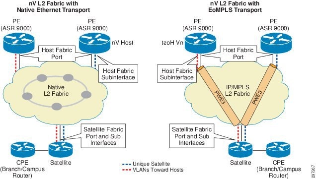
In the case of L2 Fabric, a unique VLAN is allocated for the point-to-point emulated connection between the Host and each Satellite device. The host uses such VLAN for the advertisement of multicast discovery messages.
Satellite devices listen for discovery messages on all the ports and dynamically create a subinterface based on the port and VLAN pair on which the discovery messages were received. VLAN configuration at the satellite is not required.
The satellite uses this auto-discovered subinterface for the establishment of a management session and for the exchange of all upstream and downstream traffic with each of the hosts (data and control). At the host, incoming and outgoing traffic is associated to the corresponding satellite node based on VLAN assignment. nV L2 fabric access configuration is described below.
nV L2 Fabric Configuration
Step 1![]() Interface acting as Fabric link connecting to nV ring.
Interface acting as Fabric link connecting to nV ring.
Step 2![]() Interface acting as Fabric link connecting to nV ring.
Interface acting as Fabric link connecting to nV ring.
Step 3![]() Enter nV configuration mode under interface.
Enter nV configuration mode under interface.
Step 4![]() Define fabric link connectivity to satellite 210.
Define fabric link connectivity to satellite 210.
Step 5![]() Configure Ethernet cfm to detect connectivity failure to the fabric link.
Configure Ethernet cfm to detect connectivity failure to the fabric link.
Step 6![]() Enter Redundancy configuration mode for ICP group 210.
Enter Redundancy configuration mode for ICP group 210.
Step 7![]() Define the Access ports of satellite ID 100
Define the Access ports of satellite ID 100
Step 8![]() Virtual Interface configuration corresponding to satellite 100. Interface is configured with the VRF for L3VPN service.
Virtual Interface configuration corresponding to satellite 100. Interface is configured with the VRF for L3VPN service.
Step 9![]() Configure ICCP redundancy group 210 and defines peer PE address in the redundancy group.
Configure ICCP redundancy group 210 and defines peer PE address in the redundancy group.
Step 10![]() Configure system mac for nV communication.
Configure system mac for nV communication.
Step 11![]() Enter nV configuration mode to define satellites.
Enter nV configuration mode to define satellites.
Step 12![]() Define the Satellite ID 210 and type of platform ASR 901.
Define the Satellite ID 210 and type of platform ASR 901.
Step 13![]() Define the priority for the Host PE.
Define the priority for the Host PE.
Step 14![]() Satellite chassis serial number to identify satellite.
Satellite chassis serial number to identify satellite.
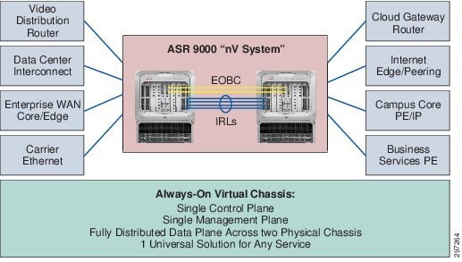
nV Cluster
ASR 9000 NV Cluster system is designed to simplify L3VPN, L2VPN. and Multicast dual-homing topologies and resiliency designs by making two ASR9k systems operate as one logical system. An NV cluster system has these properties and covers some of use cases (partial list) described in Figure 4-6.
- Without an ASR9k cluster, a typical MPLS-VPN dual-homing scenario has a CE dual-homed to two PEs where each PE has its own BGP router ID, PE-CE peering, security policy, routing policy maps, QoS, and redundancy design, all of which can be quite complex from a design perceptive.
- With a ASR9k Cluster system, both PEs will share a single control plane, a single management plane, and a fully distributed data plane across two physical chassis, and support one universal solution for any service including L3VPN, L2VPN, MVPN, Multicast, etc. The two clustered PEs can be geographically redundant by connecting the cluster ports on the RSP440 faceplate, which will extend the EOBC channel between the rack 0 and rack 1 and operate as a single XR ASR9k router. For L3VPN, we will use one BGP router ID with the same L3VPN instance configured on both rack 0 and rack 1 and have one BGP router ID and peering with CEs and remote PEs.
Figure 4-6 ASR 9000 nV Cluster Use Cases for Universal Resiliency Scheme
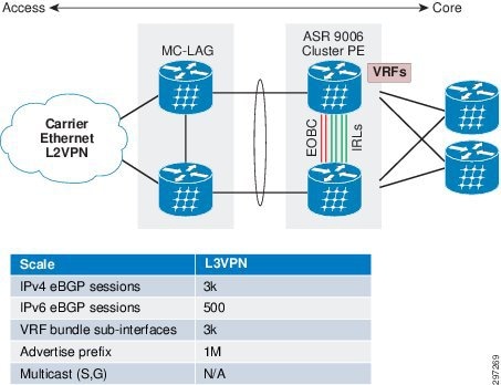
In the topology depicted and descibed in Figure 4-7, we tested and measured L3VPN convergence time using a clustered system and compared it against VRRP/HSRP. We tested both cases with identical scale and configuration as shown in the table in Figure 4-7. We also measured access-to-core and core-to-access traffic convergence time separately for better convergence visibility.
Figure 4-7 L3VPN Cluster Convergence Test Topology
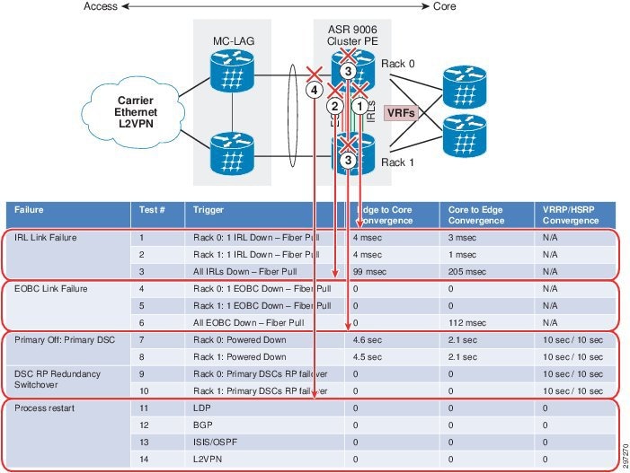
The convergence results of L3VPN cluster system versus VRRP/HSRP are summarized in Figure 4-8. We covered the five types of failure tests listed below.

Note![]() We repeated each test three times and reported the worst-case numbers of three trials.
We repeated each test three times and reported the worst-case numbers of three trials.
- IRL link failure
- EOBC link failure
- Power off Primary DSC failover
- DSC RP redundancy switchover
- Process restart
Figure 4-8 L3VPN Cluster Convergence Results versus VRRP/HSRP
nV Cluster PE with L3vpn Service can be implemented on ASR9000 Rack0 and Rack1 as described below.
nV Cluster Configuration
Step 1![]() Configure Rack ID 1 for rack 1 in ROMmon mode.
Configure Rack ID 1 for rack 1 in ROMmon mode.
Step 2![]() Configure Rack ID 0 for rack 0 in ROMmon mode.
Configure Rack ID 0 for rack 0 in ROMmon mode.
Step 3![]() Configure nV Edge in Admin mode. Required only on Rack 0.
Configure nV Edge in Admin mode. Required only on Rack 0.
Step 4![]() Configure nV Edge in Admin mode. Required only on Rack 0.
Configure nV Edge in Admin mode. Required only on Rack 0.
Step 5![]() Configure Serial Number of Rack 0.
Configure Serial Number of Rack 0.
Step 6![]() Configure Serial Number of Rack 1.
Configure Serial Number of Rack 1.
Step 7![]() Configure Inter Rack Links (L1 links). Used for forwarding packets whose ingress and egress interfaces are on separate racks.
Configure Inter Rack Links (L1 links). Used for forwarding packets whose ingress and egress interfaces are on separate racks.
Step 8![]() Configure the interface as nV Edge interface.
Configure the interface as nV Edge interface.
Step 9![]() Configure mandatory LACP configuration for Bundle interfaces.
Configure mandatory LACP configuration for Bundle interfaces.
Step 10![]() Configure Bundle interface.
Configure Bundle interface.
Step 11![]() Configure VRF service.
Configure VRF service.
Step 12![]() nV Edge requires a manual configuration of mac-address under the Bundle interface.
nV Edge requires a manual configuration of mac-address under the Bundle interface.
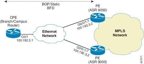
Native IP-Connected Access
In Native Ethernet Access topology, the branch or campus router is dual homed to PEs with redundancy and load balancing mechanisms being taken care by the Routing protocol configuration. VRF service is configured on both PE's interfaces connecting to CPE. CPE can be connected to the PEs using direct links or through normal Ethernet access network. The configuration on the CPE decides which PE will be used as the primary to send traffic.
- If the BGP is the routing protocol between PE and CE, high local preference is configured on CE for primary PE so that best path is selected for primary PE.
- In the case of static routing, floating static routes are configured on CPE such that static route with lower Administrative distance points to primary PE and higher AD to backup PE. BFD is used for fast failure detection to detect fast failure of BGP Peer or static route.
Figure 4-9 Native IP-Connected Access
Native IP-connected configuration is shown in Table 4-3 .
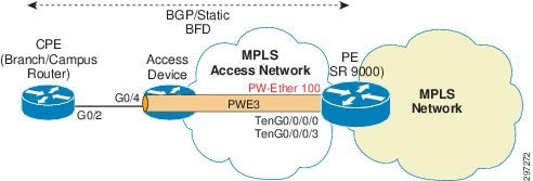
MPLS Access using Pseudowire Headend
In MPLS Access, Enterprise access devices are connected to the ASR9000 PE devices with the MPLS-enabled network between access devices and PE devices. The branch or campus router is connected to the access device via an Ethernet 802.1Q-tagged interface. The access device is configured with a pseudowire terminating on the PE device on a Pseudowire Headend interface.
Pseudowire Headend (PWHE) is a technology that allows termination of access PWs into an L3 (VRF or global) domain, therefore eliminating the requirement of keeping separate interfaces for terminating pseudowire and L3VPN service. PWHE introduces the construct of a "pw-ether" interface on the PE device. This virtual pw-ether interface terminates the PWs carrying traffic from the CPE device and maps directly to an MPLS VPN VRF on the provider edge device. Any QoS and ACLs are applied to the pw-ether interface.
All traffic between CE and PE is tunneled in this pseudowire. Access network runs its LDP/IGP domain along with Labeled BGP, as mentioned in Large Scale Network Design and Implementation, and learns PE loopback address accordingly for PW connectivity. The access device can initiate this pseudowire using two methods:
- Per Access Port Method in which the pseudowire is configured directly on the interface connecting to CPE or
- Per Access Node Method in which the pseudowire is configured on SVI corresponding, therefore taking traffic from multiple ports in a single pseudowire.
This guide focuses on the Per Access Port topology.
Access device is configured with XConnect on the interface connecting to the branch/campus router. The XConnect peer is configured as the PE loopback address. On PE PW-ether, an interface is created on which the XConnect is terminating. The same PW-ether interface is also configured with VRF and L3VPN service is configured on it. The PE and CE can use any routing protocol to exchange route information over PW-Ether Interface. BFD is used between PE and CE for fast failure detection.
PWHE configuration is described as below.
Figure 4-10 depicts MPLS Access using PWHE.
Figure 4-10 MPLS Access using Pseudowire Headend
Access Device Configuration
Step 1![]() Configure PW class on the access device.
Configure PW class on the access device.
Step 2![]() Enter Interface configuration of CE-connecting interface.
Enter Interface configuration of CE-connecting interface.
Step 3![]() Configure XConnect on the Access device towards PE with encapsulation MPLS and PW-class BUS_PWHE to inherit its parameters.
Configure XConnect on the Access device towards PE with encapsulation MPLS and PW-class BUS_PWHE to inherit its parameters.
PE Configuration
Step 1![]() Configure PWHE interface.
Configure PWHE interface.
Step 2![]() Configure VRF under PWHE interface.
Configure VRF under PWHE interface.
Step 3![]() Attach interface list to the PWHE interface.
Attach interface list to the PWHE interface.
Step 4![]() Attach the interfaces to the list.
Attach the interfaces to the list.
Step 5![]() Assign interfaces to the list.
Assign interfaces to the list.
Step 6![]() Configure BGP in AS 101.
Configure BGP in AS 101.
Step 7![]() Enter VRF configuration under BGP.
Enter VRF configuration under BGP.
Step 8![]() Configure neighbor address as PE.
Configure neighbor address as PE.
Step 9![]() Configure remote AS as CE AS.
Configure remote AS as CE AS.
Step 10![]() Enable BFD to detect failures in the path between adjacent forwarding engines.
Enable BFD to detect failures in the path between adjacent forwarding engines.
Step 11![]() Configure BFD multiplier.
Configure BFD multiplier.
Step 12![]() Configure Minimum Interval between sending BFD hello packets to the neighbor.
Configure Minimum Interval between sending BFD hello packets to the neighbor.
Step 13![]() Enters IPv4 address family.
Enters IPv4 address family.
Step 14![]() Configure route-filter to permit all incoming routes.
Configure route-filter to permit all incoming routes.
Step 15![]() Configure route-filter to permit all outgoing routes.
Configure route-filter to permit all outgoing routes.
Step 16![]() Enter L2VPN configuration mode.
Enter L2VPN configuration mode.
Step 18![]() Configure XConnect on the PWHE interface PW-Ether100 and mentioning access device as neighbor.
Configure XConnect on the PWHE interface PW-Ether100 and mentioning access device as neighbor.
Step 19![]() Configure route-policy.
Configure route-policy.
CE Configuration
Step 1![]() Interface connecting to the Access device.
Interface connecting to the Access device.
Step 2![]() Configure BFD for fast failure detection.
Configure BFD for fast failure detection.
Step 4![]() Ipv6 PE neighbor with remote as 101.
Ipv6 PE neighbor with remote as 101.
Step 5![]() Ipv4 PE neighbor with remote as 101.
Ipv4 PE neighbor with remote as 101.
To achieve PE level redundancy, another link can be used between the CPE and the access node and on that link, the access node can be configured with another pseudowire terminating at another PE.
 Feedback