- Small Network Design and Implementation
Enterprise Network Virtualization Design
This Cisco Validated Design (CVD) focuses on the role of Cisco ASR 9000 Series Aggregation Services Routers (ASR 9000) as P and PE devices in the Multiprotocol Label Switching (MPLS) L3VPN architecture described in Figure 2-2. Providers can use this architecture to implement network infrastructures that connect virtual networks among data centers, branch offices, and campuses using all types of WAN connectivity.
In this architecture, data centers (branch or campus) are considered customer edge (CE) devices. The design considers provider (P) and provider edge (PE) router configuration with the following connectivity control and data plane options between PE and CE routers:
- Ethernet hub-and-spoke or ring
- IP
- Network virtualization (nV)
- Pseudowire Headend (PWHE) for MPLS CE routers
Two options are considered for the MPLS L3VPN infrastructure incorporating P and PE routers:
- A flat LDP domain option, which is appropriate for smaller MPLS VPN deployments (700-1000 devices).
- A hierarchical design using RFC 3107-labeled BGP to segment P and PE domains into IGP domains to help scale the infrastructure well beyond 50,000 devices.
This chapter first examines topics common to small and large network implementations. These topics are discussed in the context of small network design. Later, it looks at additional technologies needed to enable small networks to support many more users. This chapter includes the following major topics:
Small Network Design and Implementation
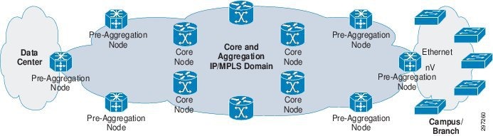
Figure 3-1 shows the small network deployment topology.
Figure 3-1 Small Deployment Topology
–![]() Scale target for this architecture is less than 700 IGP/LDP nodes
Scale target for this architecture is less than 700 IGP/LDP nodes
- All VPN configuration is on the PE nodes.
- Connectivity between the PE Node and the branch/campus router includes the following options:
–![]() Ethernet hub-and-spoke or ring
Ethernet hub-and-spoke or ring
–![]() PWHE to collapse CE into PE as nV alternative
PWHE to collapse CE into PE as nV alternative
The domain of P and PE routers, which is no greater than a few hundred, can be implemented using single IGP and LDP instances. On the left is the data center, with the network extending across the WAN to branch and campus locations.
PE Operation and Configuration
PE routers must perform multiple tasks, separating individual group control and data planes, and advertising routes between sites in the same VPN.
This functionality is achieved by creating VRF instances to provide separate data and control plane for the L3VPN. VRFs are configured with route distinguishers, which are unique for a particular VRF on the PE device. MP-BGP, which is configured on PEs, advertises and receives VRF prefixes appended with route distinguishers, which are also called VPNv4 prefixes.
Each VRF is also configured with a route target, which is a BGP-extended community representing a VPN that is tagged to VPNv4 prefixes when a route is advertised or exported from PE. Remote PEs selectively import only those VPNV4 prefixes into their VRF, which are tagged with the RT that matches the configured VRF-imported RT. PE can use static routing or run routing protocols with CPE at branches to learn prefixes. Unless there is a compelling reason to do otherwise in the design, route targets and route distinguishers are set to the same values to simplify configuration.
VRF Configuration
VRF configuration comprises the following major steps, which are described in detail in the subsequent sections:
- Defining a unique VRF name on the PE.
- Configuring a route distinguisher value for the VRF under router BGP so that VRF prefixes can be appended with RD value to make VPNv4 prefixes.
- Importing and exporting route targets corresponding to the VPN in the VRF configuration so that PE can advertise routes with the assigned export route target and download prefixes tagged with configured import route target into the VRF table.
- Applying the VRF on the corresponding interface connected to CPE.
PE VRF Configuration
Step 1![]() Configure a VRF named BUS-VPN2.
Configure a VRF named BUS-VPN2.
Step 2![]() Enter IPv4 address-family configuration mode for VRF.
Enter IPv4 address-family configuration mode for VRF.
Step 3![]() Configure the import route target to selectively import IPv4 routes into the VRF matching the route target.
Configure the import route target to selectively import IPv4 routes into the VRF matching the route target.
Step 4![]() Configure the export route target to tag IPv4 routes having this route target while advertising to remote PE routers.
Configure the export route target to tag IPv4 routes having this route target while advertising to remote PE routers.
Step 5![]() Enter IPv6 address-family configuration mode for VRF.
Enter IPv6 address-family configuration mode for VRF.
Step 6![]() Configure the import route target to selectively import IPv6 routes into the VRF matching the route target.
Configure the import route target to selectively import IPv6 routes into the VRF matching the route target.
Step 7![]() Configure the export route target to tag IPv6 routes having this route target while advertising to remote PE routers.
Configure the export route target to tag IPv6 routes having this route target while advertising to remote PE routers.
Step 8![]() Enter router BGP configuration mode.
Enter router BGP configuration mode.
Step 9![]() Enter VRF BGP configuration mode.
Enter VRF BGP configuration mode.
Step 10![]() Define the route distinguisher value for the VRF. The route distinguisher is unique for each VRF in each PE router.
Define the route distinguisher value for the VRF. The route distinguisher is unique for each VRF in each PE router.
Step 11![]() Enter VRF IPv4 address-family configuration mode.
Enter VRF IPv4 address-family configuration mode.
Step 12![]() Redistribute directly-connected IPv4 prefixes.
Redistribute directly-connected IPv4 prefixes.
Step 13![]() Enter VRF IPv6 address-family configuration mode.
Enter VRF IPv6 address-family configuration mode.
Step 14![]() Redistribute directly-connected IPv6 prefixes.
Redistribute directly-connected IPv6 prefixes.
Step 15![]() Enter CPE-facing interface configuration mode.
Enter CPE-facing interface configuration mode.
Step 16![]() Configure VRF on the interface.
Configure VRF on the interface.
At this stage, the L3 VRF and the route distinguisher are configured to append to routes coming into the VRF. The route distinguisher enables multiple VPN clients to use overlapping IP address spaces. The L3VPN core can differentiate overlapping addresses because each IP address is appended with a route distinguisher and therefore is globally unique. Combined client IP addresses and route distinguishers are referred to as VPNv4 addresses.
To get routes from a client site at the CE (branch or campus router) into the VRF, either static routing or a routing protocol is used. Examples of the most common static routing and eBGP scenarios follow.
PE-CE Routing Protocol Configuration
This section describes how to configure PE-CE routing protocols.
PE eBGP Routing Configuration with CPE
PE is configured with an Exterior Border Gateway protocol (eBGP) session with CPE in the VRF under address-family IPv4 to exchange IPv4 prefixes with CPE. Routes learned from CPE are advertised to remote PEs using MP-BGP.
The following procedure illustrates the configuration.
Step 1![]() Enter router BGP configuration mode.
Enter router BGP configuration mode.
Step 2![]() Enter VRF BGP configuration mode.
Enter VRF BGP configuration mode.
Step 3![]() Configure the CPE IP address as a BGP peer and its autonomous system (AS) as remote-as.
Configure the CPE IP address as a BGP peer and its autonomous system (AS) as remote-as.
Step 4![]() Enter VRF IPv4 address-family configuration mode for BGP.
Enter VRF IPv4 address-family configuration mode for BGP.
PE Static Routing Configuration with CPE
PE is configured using static routes in the VRF, with next-hop as the CPE address. Configuration use IPv4 address-family to configure IPv4 static routes. The static routes are then advertised to remote PEs by redistributing under BGP.
The following procedure illustrates the configuration.
Step 1![]() Enter router static configuration mode for the VRF.
Enter router static configuration mode for the VRF.
Step 2![]() Enter VRF IPv4 address-family configuration mode for static.
Enter VRF IPv4 address-family configuration mode for static.
Step 3![]() Configure Static route 100.192.194.0/24 with next hop 100.192.40.3
Configure Static route 100.192.194.0/24 with next hop 100.192.40.3
Step 4![]() Redistribute Static Prefixes under BGP VRF address-family IPv4 so that they are advertised to remote PEs.
Redistribute Static Prefixes under BGP VRF address-family IPv4 so that they are advertised to remote PEs.
After routes from the branch or campus router are in the client VRF, the routes must be advertised to other sites in the L3VPN to enable reachability. Reachability is delivered using MP-BGP to advertise VPNv4 addresses, associated with the VRF at the branch location, to members of the same VPN.
PE MP-BGP Configuration
MP-BGP configuration comprises BGP peering with route reflector for VPNv4 and VPNv6 address families to advertise and receive VPNv4 and VPNv6 prefixes. MP-BGP uses session-group to configure address-family independent (global) parameters; peers requiring the same parameters can inherit its configuration.
Session-group includes update-source, which specifies the interface whose address is used for BGP communication, and remote-as, which specifies the AS number to which the CPE belongs. Neighbor-group is configured to import session-group for address-family independent parameters, and to configure address-family dependent parameters, such as next-hop-self, in the corresponding address-family.
The following procedure illustrates MP-BGP configuration on PE.
Step 1![]() Enter Router BGP configuration mode.Step TBD
Enter Router BGP configuration mode.Step TBD
Step 2![]() Step TBD Configured BGP Router-ID
Step TBD Configured BGP Router-ID
Step 3![]() Configure the VPNv4 unicast address-family to exchange VPNv4 prefixes.
Configure the VPNv4 unicast address-family to exchange VPNv4 prefixes.
Step 4![]() Configure the VPNv6 unicast address-family to exchange VPNv4 prefixes.
Configure the VPNv6 unicast address-family to exchange VPNv4 prefixes.
Step 5![]() Configure session-group to define address-family independent parameters.
Configure session-group to define address-family independent parameters.
Step 6![]() Specify remote-as as the route reflector AS number.
Specify remote-as as the route reflector AS number.
Step 7![]() Specify update-source as Loopback0 for BGP communication.
Specify update-source as Loopback0 for BGP communication.
Step 8![]() Enter neighbor-group configuration mode.
Enter neighbor-group configuration mode.
Step 9![]() Import session-group address-family independent parameters.
Import session-group address-family independent parameters.
Step 10![]() Enable vpnv4 address-family for neighbor group and configure address-family dependent pa-rameters under VPNv4 address-family.
Enable vpnv4 address-family for neighbor group and configure address-family dependent pa-rameters under VPNv4 address-family.
Step 11![]() Enable vpnv6 address-family for neighbor group and configure address-family dependent pa-rameters under VPNv6 AF.
Enable vpnv6 address-family for neighbor group and configure address-family dependent pa-rameters under VPNv6 AF.
Step 12![]() Import the neighbor-group route-reflector to define the route-reflector address as a VPNv4 and VPNv6 peer.
Import the neighbor-group route-reflector to define the route-reflector address as a VPNv4 and VPNv6 peer.
The above sections described how we can configure virtual networks on a PE router. The network can have hundreds of PE routers connecting to Campus/Branch Routers and Data centers. A PE router in one location learns VRF prefixes of remote location using Multiprotocol IBGP. PEs cannot advertise VPNv4 prefix received from one IBGP peer to another due to IBGP split-horizon rule. IBGP requires a full mesh between all IBGP-speaking PEs. It can cause scalability and overhead issues as PE routers require maintaining the IBGP session with all remote PEs and sending updates to all IBGP peers; this causes causing duplication. To address this issue, route reflectors can be deployed, as explained below.
Route Reflector Operation and Configuration
Route reflectors (RR) addresses the scalability and overhead issues of requiring full mesh of IBGP sessions because of the IBGP split-horizon rule. When a device is assigned as a RR, and PE devices are assigned as its clients, the split horizon rule is relaxed on the RR, enabling the route protector to the prefixes received from one client PE to another client PE. PEs must maintain IBGP sessions with the RR only to send and receive updates. The RR reflects updates received from one PE to other PEs in the network, eliminating the requirement for IBGP full mesh.
By default, a RR does not change next-hop or any other prefix attributes. Prefixes received by PEs still have remote PEs as next-hop, not the RR, so PEs can send traffic directly to remote PEs. This eliminates the requirement to have the RR in the data path and RR can only be used for RR function.
Route Reflector Configuration
This section describes ASR 1000 RR configuration, which includes configuring a peer-group for router BGP. PEs having the same update policies (such as update-group, remote-as) can be grouped into the same peer group, which simplifies peer configuration and enables more efficient updating. The peer-group is made a RR client so that the RR can reflect routes received from a client PE to other client PEs.
Step 1![]() Loopback interface for IBGP session.
Loopback interface for IBGP session.
Step 2![]() Enter Router BGP configuration mode.
Enter Router BGP configuration mode.
Step 3![]() Define Peer-group rr-client.
Define Peer-group rr-client.
Step 4![]() Specify Update-source as Loopback0 for BGP communication.
Specify Update-source as Loopback0 for BGP communication.
Step 5![]() Specify remote-as as AS number of PE.
Specify remote-as as AS number of PE.
Step 6![]() Configure PE router as Peer-group member.
Configure PE router as Peer-group member.
Step 7![]() Enter VPNv4 address-family mode.
Enter VPNv4 address-family mode.
Step 8![]() Make peer-group members RR client.
Make peer-group members RR client.
Step 9![]() Configure RR to send both standard and Extended community(RT) to Peer-group members.
Configure RR to send both standard and Extended community(RT) to Peer-group members.
Step 10![]() Activate the PE as peer for VPNv4 peering under VPNv4 address-family.
Activate the PE as peer for VPNv4 peering under VPNv4 address-family.
After configuring PE with the required virtual network configuration described above, transport must be set up to carry virtual network traffic from one location to another. The next section describes how we can implement transport and optimize it with fast detection and convergence for seamless service delivery.
PE and P Transport Configuration
Transport networks, comprising PE and P routers, transport traffic from multiple L3VPNs from one location to another. To achieve seamless communication across virtual networks, transport networks require reachability and label-based forwarding across the transport domain, along with fast failure detection and convergence. Bidirectional Forwarding Detection (BFD) is used for fast failure detection. Fast convergence uses Remote Loop Free Alternate Fast Reroute (rLFA FRR) and BGP Prefix Independent Convergence (PIC). These methods are described in subsequent sections.
Transport implementation requires PE, P, and RR devices configured using IGP for reachability. These devices also use LDP to exchange labels for prefixes advertised and learned from IGP. The devices maintain a Label Forwarding Information Base (LFIB) to make forwarding decisions.
When sending VRF traffic from a branch or campus router to a remote location, PE encapsulates traffic in MPLS headers, using a label corresponding to the BGP next-hop (remote PE) for the traffic. Intermediate devices, such as P devices, examine the top label on the MPLS header, perform label swapping, and use LFIB to forward traffic toward the remote PE. P devices can ignore the VRF traffic and forward packets using only labels. This enables the establishment and use of labeled-switched paths (LSPs) when a PE device forwards VPN traffic to another location.
Fast Failure Detection Using Bidirectional Forwarding Detection
Link failure detection in the core normally occurs through loss of signal on the interface. This is not sufficient for BGP, however, because BGP neighbors are typically not on the same segment. A link failure (signal loss) at a BGP peer can remain undetected by another BGP peer. Absent some other failure detection method, reconvergence occurs only when BGP timers expire, which is too slow. BFD is a lightweight, fast hello protocol that speeds remote link failure detection.
PE and P devices use BFD as a failure detection mechanism on the CORE interfaces that informs IGP about link or node failure within a millisecond (ms). BFD peers send BFD control packets to each other on the interfaces enabled with BFD at negotiated intervals. If a BFD peer does not receive a control packet and the configured dead timer (in ms) expires, the BFD session is torn down and IGP is rapidly informed about the failure. IGP immediately tears down the session with the neighbor and switches traffic to an alternate path. This enables failure detection is achieved in ms.
Fast Convergence Using Remote Loop Free Alternate Fast Reroute
After BFD detects a failure, the next step is to "fast converge" the network to an alternate path. For IGP prefixes, LFAs enable fast. The type of LFA depends on the network topology. The first type, called simply LFA, is suitable for hub-and-spoke topologies. The second type is called remote LFA (rLFA) and is suitable for ring topologies.
- LFA FRR calculates the backup path for each prefix in the IGP routing table; if a failure is detected, the router immediately switches to the appropriate backup path in about 50 ms. Only loop-free paths are candidates for backup paths.
- rLFA FRR works differently because it is designed for cases with a physical path, but no loop-free alternate paths. In the rLFA case, automatic LDP tunnels are set up to provide LFAs for all network nodes.
Without LFA or rLFA FRR, a router calculates the alternate path after a failure is detected, which results in delayed convergence. However, LFA FRR calculates the alternate paths in advance to enable faster convergence. P and PE devices have alternate paths calculated for all prefixes in the IGP table, and use rLFA FRR to fast reroute in case of failure in a primary path.
Fast Convergence Using BGP Prefix Independent Convergence
For BGP prefixes, fast convergence is achieved using BGP PIC, in which BGP calculates an alternate best path and primary best path and installs both paths in the routing table as primary and backup paths. This functionality is similar to rLFA FRR, which is described in the preceding section. If the BGP next-hop remote PE becomes unreachable, BGP immediately switches to the alternate path using BGP PIC instead of recalculating the path after the failure. If the BGP next-hop remote PE is alive but there is a path failure, IGP rLFA FRR handles fast reconvergence to the alternate path and BGP updates the IGP next-hop for the remote PE.
PE and P Transport Configuration
This section describes how to configure PE and P transport to support fast failure detection and fast convergence.
PE Transport Configuration
PE configuration includes enabling IGP (IS-IS or OSPF can be used) to exchange core and aggregation reachability, and enabling LDP to exchange labels on core facing interfaces. A loopback interface is also advertised in IGP as the BGP VPNv4 session is created, using update-source Loopback0 as mentioned in PE Operation and Configuration. Using the loopback address to source updates and target updates to remote peers improves reliability; the loopback interface is always up when the router is up, unlike physical interfaces that can have link failures.
BFD is configured on core-facing interfaces using a 15 ms hello interval and multiplier 3 to enable fast failure detection in the transport network. rLFA FRR is used under IS-IS level 2 for fast convergence if a transport network failure occurs. BGP PIC is configured under VPNv4 address-family for fast convergence of VPNv4 Prefixes if a remote PE becomes unreachable.
The following procedure describes PE transport configuration.
Step 1![]() Loopback Interface for BGP VPNv4 neighbor ship.
Loopback Interface for BGP VPNv4 neighbor ship.
Step 3![]() Enter Router IS-IS configuration.
Enter Router IS-IS configuration.
Step 4![]() Assign NET address to the IS-IS process.
Assign NET address to the IS-IS process.
Step 5![]() Enter IPv4 address-family for IS-IS.
Enter IPv4 address-family for IS-IS.
Step 6![]() Metric style Wide generates new-style TLV with wider metric fields for IPv4.
Metric style Wide generates new-style TLV with wider metric fields for IPv4.
Step 7![]() Enter IPv6 address-family for IS-IS.
Enter IPv6 address-family for IS-IS.
Step 8![]() Metric-style Wide generates new-style TLV with wider metric fields for IPv6.
Metric-style Wide generates new-style TLV with wider metric fields for IPv6.
Step 9![]() Configure IS-IS for Loopback interface.
Configure IS-IS for Loopback interface.
Step 10![]() Make loopback passive to avoid sending unnecessary hellos on it.
Make loopback passive to avoid sending unnecessary hellos on it.
Step 11![]() Enter IPv4 Address-family for Loopback.
Enter IPv4 Address-family for Loopback.
Step 12![]() Enter IPv6 Address-family for Loopback.
Enter IPv6 Address-family for Loopback.
Step 13![]() Configure IS-IS for TenGigE0/0/0/0 interface.
Configure IS-IS for TenGigE0/0/0/0 interface.
Step 14![]() Configure IS-IS Circuit-Type on the interface.
Configure IS-IS Circuit-Type on the interface.
Step 15![]() Configure Minimum Interval between sending BFD hello packets to the neighbor.
Configure Minimum Interval between sending BFD hello packets to the neighbor.
Step 16![]() Configure BFD multiplier.
Configure BFD multiplier.
Step 17![]() Enable BFD to detect failures in the path between adjacent forwarding engines.
Enable BFD to detect failures in the path between adjacent forwarding engines.
Step 18![]() Enter the IPv4 Address-family for TenGig interface.
Enter the IPv4 Address-family for TenGig interface.
Step 19![]() Configure IS-IS metric for Interface.
Configure IS-IS metric for Interface.
Step 20![]() Enable per prefix FRR for Level 2 prefixes.
Enable per prefix FRR for Level 2 prefixes.
Step 21![]() Configure an FRR path that redirects traffic to a remote LFA tunnel.
Configure an FRR path that redirects traffic to a remote LFA tunnel.
Step 22![]() Enable mpls LDP sync to ensure LDP comes up on link before Link is used for forwarding to avoid packet loss.
Enable mpls LDP sync to ensure LDP comes up on link before Link is used for forwarding to avoid packet loss.
Step 23![]() Enter MPLS LDP configuration mode.
Enter MPLS LDP configuration mode.
Step 24![]() Configure router-id for LDP.
Configure router-id for LDP.
Step 25![]() Enable LDP on TenGig0/0/0/0.
Enable LDP on TenGig0/0/0/0.
Step 26![]() Enter BGP configuration mode.
Enter BGP configuration mode.
Step 27![]() Enter VPNv4 address-family mode.
Enter VPNv4 address-family mode.
Step 28![]() Configure receive capability of multiple paths for a prefix to the capable peers.
Configure receive capability of multiple paths for a prefix to the capable peers.
Step 29![]() Configure send capability of multiple paths for a prefix to the capable peers.
Configure send capability of multiple paths for a prefix to the capable peers.
Step 30![]() Enable BGP PIC functionality with appropriate route-policy to calculate back up paths.
Enable BGP PIC functionality with appropriate route-policy to calculate back up paths.
Step 31![]() Configure route-policy used in BGP PIC.
Configure route-policy used in BGP PIC.
Step 32![]() Configure to install 1 backup path.
Configure to install 1 backup path.
P Transport Configuration
P transport configuration includes enabling IGP (IS-IS or OSPF) to exchange core and aggregation reachability, and enabling LDP to exchange labels on core-facing interfaces. P routers are not required because VRF is not configured on them and so they do not need VPNv4 and VPNv6 prefixes. P routers know only core and aggregation prefixes in the transport network and do not need to know prefixes belonging to VPNs. P swap labels based on the top packet label belonging to remote PEs, and use LFIB to accomplish PE-to-PE LSP. rLFA FRR is used under IS-IS level 2 for fast convergence if a transport network failure occurs.
Step 1![]() Core Interface connecting to PE.
Core Interface connecting to PE.
Step 2![]() Core Interface connecting to Core MPLS network.
Core Interface connecting to Core MPLS network.
Step 3![]() Enter Router IS-IS configuration.
Enter Router IS-IS configuration.
Step 4![]() Assign NET address to the IS-IS process.
Assign NET address to the IS-IS process.
Step 5![]() Enter IPv4 address-family for IS-IS.
Enter IPv4 address-family for IS-IS.
Step 6![]() Metric-style Wide generates new-style TLV with wider metric fields for IPv4.
Metric-style Wide generates new-style TLV with wider metric fields for IPv4.
Step 7![]() Configure IS-IS for Loopback interface.
Configure IS-IS for Loopback interface.
Step 8![]() Make loopback passive to avoid sending unnecessary hellos on it.
Make loopback passive to avoid sending unnecessary hellos on it.
Step 9![]() Enter IPv4 Address-family for Loopback.
Enter IPv4 Address-family for Loopback.
Step 10![]() Configure IS-IS for TenGigE0/0/0/0 interface.
Configure IS-IS for TenGigE0/0/0/0 interface.
Step 11![]() Configure IS-IS Circuit-Type on the interface.
Configure IS-IS Circuit-Type on the interface.
Step 12![]() Configure Minimum Interval between sending BFD hello packets to the neighbor.
Configure Minimum Interval between sending BFD hello packets to the neighbor.
Step 13![]() Configure BFD multiplier.
Configure BFD multiplier.
Step 14![]() Enable BFD to detect failures in the path between adjacent forwarding engines.
Enable BFD to detect failures in the path between adjacent forwarding engines.
Step 15![]() Enter the IPv4 Address-family for TenGig interface.
Enter the IPv4 Address-family for TenGig interface.
Step 16![]() Configure IS-IS metric for Interface.
Configure IS-IS metric for Interface.
Step 17![]() Enable mpls LDP sync to ensure LDP comes up on link before Link is used for forwarding to avoid packet loss.
Enable mpls LDP sync to ensure LDP comes up on link before Link is used for forwarding to avoid packet loss.
Step 18![]() Configure IS-IS for TenGigE0/0/0/1 interface.
Configure IS-IS for TenGigE0/0/0/1 interface.
Step 19![]() Configure IS-IS Circuit-Type on the interface.
Configure IS-IS Circuit-Type on the interface.
Step 20![]() Configure Minimum Interval between sending BFD hello packets to the neighbor.
Configure Minimum Interval between sending BFD hello packets to the neighbor.
Step 21![]() Configure BFD multiplier.
Configure BFD multiplier.
Step 22![]() Enable BFD to detect failures in the path between adjacent forwarding engines.
Enable BFD to detect failures in the path between adjacent forwarding engines.
Step 23![]() Enter the IPv4 Address-family for TenGig interface.
Enter the IPv4 Address-family for TenGig interface.
Step 24![]() Configure IS-IS metric for Interface.
Configure IS-IS metric for Interface.
Step 25![]() Enable per prefix FRR for Level 2 prefixes.
Enable per prefix FRR for Level 2 prefixes.
Step 26![]() Configure an FRR path that redirects traffic to a remote LFA tunnel.
Configure an FRR path that redirects traffic to a remote LFA tunnel.
Step 27![]() Enable mpls LDP sync to ensure LDP comes up on link before Link is used for forwarding to avoid packet loss.
Enable mpls LDP sync to ensure LDP comes up on link before Link is used for forwarding to avoid packet loss.
Step 28![]() Enter MPLS LDP configuration mode.
Enter MPLS LDP configuration mode.
Step 29![]() Configure router-id for LDP.
Configure router-id for LDP.
Step 30![]() Enable LDP on TenGig0/0/0/0.
Enable LDP on TenGig0/0/0/0.
Step 31![]() Enable LDP on TenGig0/0/0/1.
Enable LDP on TenGig0/0/0/1.
QoS Operation and Implementation in the Core Network
Enterprise virtual networks consist of traffic types that include voice, video, critical applications traffic, and end user web traffic. This traffic requires different priorities and treatments based upon their characteristics and their criticality to the business. In the MPLS core network, QoS ensures proper treatment to the virtual network's traffic being transported. This is achieved as described in this section.
As discussed in previous sections, MPLS header is imposed on traffic in the Enterprise virtual network ingressing the MPLS network on PEs. When this labeled traffic is transported in the core network, QoS implementation uses 3-bit MPLS EXP bits field (0-7) present in the MPLS header for proper QoS treatment. DiffServ PHB, which defines packet-forwarding properties associated with different traffic classes, is divided into the following:
- Expedited Forwarding (EF)—Used for traffic requiring low loss, low latency, low jitter, and assured bandwidth.
- Assured Forwarding (AF)—Allows four classes with certain buffer and bandwidth.
- Best Effort (BE)—Best effort forwarding.
This guide focuses on the MPLS Uniform QoS model in which DSCP marking of received branch or campus router's traffic on PE is mapped to corresponding MPLS EXP bits. The mapping shown in Table 3-1 is used for different traffic classes to DSCP and MPLS EXP.
|
|
|
|
|
|---|---|---|---|
The QoS configuration includes configuring class-maps created for the different traffic classes mentioned above assigned with the corresponding MPLS Exp. While configuring policy maps, real-time traffic class CMAP-RT-EXP is configured with highest priority 1; it is also policed to ensure low latency expedited forwarding (EF). Rest classes are assigned with the respective required bandwidth. WRED is used as congestion avoidance mechanism for Exp 1 and 2 traffic in the Enterprise critical class CMAP-EC-EXP. The Policy-map is applied to the PE and P Core interfaces in egress direction across the MPLS network.
PE and P Core QoS Configuration
Step 1![]() Class-map for the Enterprise critical traffic.
Class-map for the Enterprise critical traffic.
Step 2![]() Matching MPLS experimental 1 OR 2 from traffic topmost MPLS header.
Matching MPLS experimental 1 OR 2 from traffic topmost MPLS header.
Step 3![]() Class map for Enterprise Telepresence traffic.
Class map for Enterprise Telepresence traffic.
Step 4![]() Matching MPLS experimental 3 from traffic topmost MPLS header.
Matching MPLS experimental 3 from traffic topmost MPLS header.
Step 5![]() Class-map for video traffic.
Class-map for video traffic.
Step 6![]() Matching MPLS experimental 4 from traffic topmost MPLS header.
Matching MPLS experimental 4 from traffic topmost MPLS header.
Step 7![]() Class-map for real-time traffic.
Class-map for real-time traffic.
Step 8![]() Match MPLS experimental 5 from traffic topmost MPLS header.
Match MPLS experimental 5 from traffic topmost MPLS header.
Step 9![]() Class-map for control traffic.
Class-map for control traffic.
Step 10![]() Match MPLS experimental 6 from traffic topmost MPLS header.
Match MPLS experimental 6 from traffic topmost MPLS header.
Step 11![]() Class-map for Network Management traffic.
Class-map for Network Management traffic.
Step 12![]() Match MPLS experimental 7 from traffic topmost MPLS header.
Match MPLS experimental 7 from traffic topmost MPLS header.
Step 13![]() Policy-map configuration for 10gig Link.
Policy-map configuration for 10gig Link.
Step 15![]() Define top priority 1 for the class for low-latency queuing.
Define top priority 1 for the class for low-latency queuing.
Step 16![]() Police the priority class.
Police the priority class.
Step 17![]() Assign the desired bandwidth to the class.
Assign the desired bandwidth to the class.
Step 18![]() Use WRED for Enterprise critical class for both Exp 1 and 2 for congestion avoidance. Experimental 1 will be dropped early.
Use WRED for Enterprise critical class for both Exp 1 and 2 for congestion avoidance. Experimental 1 will be dropped early.
Step 19![]() Core interface on P or PE.
Core interface on P or PE.
Step 20![]() Egress service policy on the interface.
Egress service policy on the interface.
Large Scale Network Design and Implementation
When an MPLS network comprises more than 1000 devices, implementing a hierarchical network design is recommended. In this guide, the hierarchical network design uses labeled BGP, as defined in RFC 3107. Figure 3-2 shows a network with hierarchy.
Figure 3-2 Large Network, Ethernet/SDH/nV Branch Connectivity
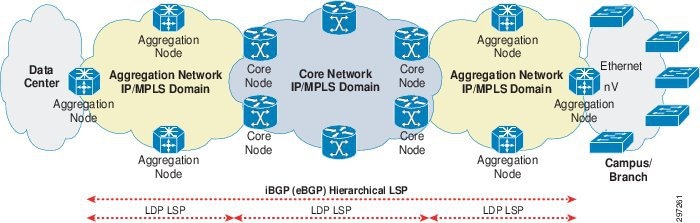
- The core and aggregation networks add hierarchy with 3107 ABR at border of core and aggregation.
- The core and aggregation networks are organized as independent IGP/LDP domains.
- The network domains are interconnected with hierarchical LSPs based on RFC 3107, BGP IPv4+labels. Intra-domain connectivity is based on LDP LSPs.
- Topologies between the PE Node and branch router can be Ethernet hub-and-spoke, IP, Ethernet ring, or nV.
Using Core Network Hierarchy to Improve Scale
The main challenges of large network implementation result from network size, such as the size of routing and forwarding tables in individual P and PE devices caused by the large number of network nodes, and trying to run all nodes in one IGP/LDP domain. In an MPLS environment, unlike in an all-IP environment, all service nodes need a /32 network address as a node identifier. /32 addresses, however, cannot be summarized, because link state databases grow in a linear fashion as devices are added to the MPLS network.
The labeled BGP mechanism, defined in RFC 3107, can be used so that link state databases in core network devices do not have to learn the /32 addresses of all MPLS routers in the access and aggregation domains. The mechanism effectively moves prefixes from the IG link state database into the BGP table. Labeled BGP, implemented in the MPLS transport network, introduces hierarchy in the network to provide better scalability and convergence. Labeled BGP ensures all devices only receive needed information to provide end-to-end transport.
Large-scale MPLS transport networks used to transport virtual network traffic can be divided into two IGP areas. In the Open Shortest Path First (OSPF) backbone area, the core network is configured using Intermediate System to Intermediate System (IS-IS) L2. In the OSPF non-backbone area, the aggregation network is configured with IS-IS L1. Another option is to run different IGP processes in the core and aggregation networks. No redistribution occurs between core and aggregation IGP levels/areas/processes, which helps to reduce the size of the routing and forwarding tables of the routers in each domain and provides better scalability and faster convergence. Running IGP in the area enables intra-area reachability, and LDP is used to build intra-area LSPs.
Because route information is not redistributed between different IGP levels/areas, PE devices need a mechanism to reach PE device loopbacks in other area/levels and send VPN traffic. Labeled BGP enables inter-area reachability and accomplish end-to-end LSP between PEs. Devices that are connected to both aggregation and core domains are called Area Border Routers (ABRs). ABRs run labeled Interior BGP (iBGP) sessions with PEs in their local aggregation domain and serve as route reflectors for the PEs. PEs advertise their loopback addresses (used for VPNv4 peering) and their corresponding labels to local route reflector ABRs using labeled IBGP. ABRs run labeled IBGP sessions with a RR device in the core domain, which reflects PE loopback addresses and labels learned from one ABR client to other ABR clients without changing next-hop or other attributes. ABRs learn PE loopback addresses and labels from other aggregation domains and advertise them to PEs in their local aggregation domain. ABRs use next-hop-self while advertising routes to PEs in local aggregation domain and to RRs in the core domain.
This makes PEs learn remote PE loopback addresses and labels with local ABR as BGP next-hop and ABRs learn remote PE loopback addresses with remote ABR as the BGP next-hop. PEs use two transport labels when sending labeled VPN traffic to the MPLS cloud: one label for remote PE and another label for its BGP next-hop (local ABR). The top label for BGP next-hop local ABR is learned from local IGP/LDP. The label below that, for remote PE, is learned through labeled IBGP with the local ABR. Intermediate devices across different domains perform label swapping based on the top label in received MPLS packets. This achieves end-to-end hierarchical LSP without running the entire network in a single IGP/LDP domain. Devices learn only necessary information, such as prefixes in local domains and remote PE loopback addresses, which makes labeled BGP scalable for large networks.
Figure 3-3 Large Network Control and Data Plane
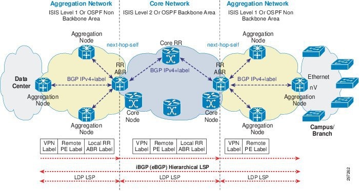
- Aggregation domains run ISIS level-1/OSPF non-backbone area and core domain runs ISIS level-2/backbone area.
- ABR connects to both aggregation and core domains.
- ABR runs Labeled iBGP with PEs in local aggregation domain and core RR in core domain.
- ABR uses next-hop-self while advertising routes to PEs and core RR.
Large Scale Hierarchical Core and Aggregation Networks with Hierarchy
PE routers are configured in IS-IS level-1 (OSPF non-backbone area) to implement ABR, PE, and core RR transport configuration for large scale MPLS VPNs. ABR aggregation domain facing interfaces are configured using IS-IS level-1 (OSPF non-backbone area) and core domain-facing interface configured with IS-IS Level-2(OSPF backbone area). Core RR interfaces will remain in IS-IS Level-2 (Or OSPF backbone area). PE and local ABR are configured with Labeled IBGP session with ABR as RR. Core RR is configured with Labeled BGP peering with all ABRs. LDP is configured in a similar way to the smaller network. ABR is configured with next-hop-self for both PE and core-labeled BGP peers to achieve hierarchical LSP. BFD is used on all interfaces as a fast failure detection mechanism. BGP PIC is configured for fast convergence of IPv4 prefixes learnt through labeled IBGP. rLFA FRR is configured under IS-IS for providing fast convergence of IGP learnt prefixes.
ABR's loopbacks are required in both aggregation and core domains since their loopbacks are used for labeled BGP peering with PEs in local aggregation domain as well as RR in the core domain. To achieve this, ABR loopbacks are kept in the IS-IS Level-1-2 or OSPF backbone area.
PE Transport Configuration
Step 1![]() Enter router IS-IS configuration for PE.
Enter router IS-IS configuration for PE.
Step 3![]() Define is-type as level 1 for the PE in aggregation domain.
Define is-type as level 1 for the PE in aggregation domain.
Step 4![]() Enter IPv4 address-family for IS-IS.
Enter IPv4 address-family for IS-IS.
Step 5![]() Metric-style Wide generates new-style TLV with wider metric fields for IPv4.
Metric-style Wide generates new-style TLV with wider metric fields for IPv4.
Step 6![]() Configure IS-IS for Loopback interface.
Configure IS-IS for Loopback interface.
Step 7![]() Make loopback passive to avoid sending unnecessary hellos on it.
Make loopback passive to avoid sending unnecessary hellos on it.
Step 8![]() Enter IPv4 Address-family for Loopback.
Enter IPv4 Address-family for Loopback.
Step 9![]() Configure IS-IS for TenGigE0/2/0/0 interface.
Configure IS-IS for TenGigE0/2/0/0 interface.
Step 10![]() Configure minimum interval between sending BFD hello packets to the neighbor.
Configure minimum interval between sending BFD hello packets to the neighbor.
Step 11![]() Configure BFD multiplier.
Configure BFD multiplier.
Step 12![]() Enable BFD to detect failures in the path between adjacent forwarding engines.
Enable BFD to detect failures in the path between adjacent forwarding engines.
Step 13![]() Configure point-to-point IS-IS interface.
Configure point-to-point IS-IS interface.
Step 14![]() Enter the IPv4 Address-family for TenGig interface.
Enter the IPv4 Address-family for TenGig interface.
Step 15![]() Enable per prefix FRR for Level 2 prefixes.
Enable per prefix FRR for Level 2 prefixes.
Step 16![]() Configure an FRR path that redirects traffic to a remote LFA tunnel.
Configure an FRR path that redirects traffic to a remote LFA tunnel.
Step 17![]() Configure IS-IS metric for Interface.
Configure IS-IS metric for Interface.
Step 18![]() Enable mpls LDP sync to ensure LDP comes up on link before link is used for forwarding to avoid packet loss.
Enable mpls LDP sync to ensure LDP comes up on link before link is used for forwarding to avoid packet loss.
Step 19![]() Enter router BGP configuration mode.
Enter router BGP configuration mode.
Step 20![]() Enter IPv4 address-family.
Enter IPv4 address-family.
Step 21![]() Configure receive capability of multiple paths for a prefix to the capable peers.
Configure receive capability of multiple paths for a prefix to the capable peers.
Step 22![]() Configure send capability of multiple paths for a prefix to the capablepeers.
Configure send capability of multiple paths for a prefix to the capablepeers.
Step 23![]() Enable BGP PIC functionality with appropriate route-policy to calculate back up paths.
Enable BGP PIC functionality with appropriate route-policy to calculate back up paths.
Step 24![]() Configure session-group to define parameters that are address-family independent.
Configure session-group to define parameters that are address-family independent.
Step 25![]() Specify remote-as as AS number of RR.
Specify remote-as as AS number of RR.
Step 26![]() Specify Update-source as Loopback0 for BGP communication.
Specify Update-source as Loopback0 for BGP communication.
Step 27![]() Enter neighbor-group configuration mode.
Enter neighbor-group configuration mode.
Step 28![]() Import Session-group AF-independent parameters.
Import Session-group AF-independent parameters.
Step 29![]() Enable Labeled BGP address-family for neighbor group.
Enable Labeled BGP address-family for neighbor group.
Step 30![]() Configure ABR loopback as neighbor.
Configure ABR loopback as neighbor.
Step 31![]() Inherit neighbor-group ABR parameters.
Inherit neighbor-group ABR parameters.
Step 32![]() Configure route-policy used in BGP PIC.
Configure route-policy used in BGP PIC.
Step 33![]() Configure to install 1 backup path.
Configure to install 1 backup path.
Step 34![]() Enter MPLS LDP configuration mode.
Enter MPLS LDP configuration mode.
Step 35![]() Configure router-id for LDP.
Configure router-id for LDP.
Step 36![]() Enable LDP on TenGig0/2/0/0.
Enable LDP on TenGig0/2/0/0.
ABR Transport Configuration
Step 1![]() Enter Router IS-IS configuration for PE.
Enter Router IS-IS configuration for PE.
Step 3![]() Enter IPv4 address-family for IS-IS.
Enter IPv4 address-family for IS-IS.
Step 4![]() Metric-style Wide generates new-style TLV with wider metric fields for IPv4.
Metric-style Wide generates new-style TLV with wider metric fields for IPv4.
Step 5![]() Configure IS-IS for Loopback interface.
Configure IS-IS for Loopback interface.
Step 6![]() Make loopback passive to avoid sending unnecessary hellos on it.
Make loopback passive to avoid sending unnecessary hellos on it.
Step 7![]() Enter IPv4 address-family for Loopback.
Enter IPv4 address-family for Loopback.
Step 8![]() Configure IS-IS for TenGigE0/2/0/0 interface.
Configure IS-IS for TenGigE0/2/0/0 interface.
Step 9![]() Configure aggregation-facing interface as IS-IS level-1 interface.
Configure aggregation-facing interface as IS-IS level-1 interface.
Step 10![]() Configure minimum interval between sending BFD hello packets to the neighbor.
Configure minimum interval between sending BFD hello packets to the neighbor.
Step 11![]() Configure BFD multiplier
Configure BFD multiplier
Step 12![]() Enable BFD to detect failures in the path between adjacent forwarding engines.
Enable BFD to detect failures in the path between adjacent forwarding engines.
Step 13![]() Configure point-to-point IS-IS interface.
Configure point-to-point IS-IS interface.
Step 14![]() Enable per prefix FRR for Level 2 prefixes.
Enable per prefix FRR for Level 2 prefixes.
Step 15![]() Configure an FRR path that redirects traffic to a remote LFA tunnel.
Configure an FRR path that redirects traffic to a remote LFA tunnel.
Step 16![]() Configure IS-IS metric for Interface.
Configure IS-IS metric for Interface.
Step 17![]() Enable MPLS LDP sync to ensure LDP comes up on link before link is used for forwarding to avoid packet loss.
Enable MPLS LDP sync to ensure LDP comes up on link before link is used for forwarding to avoid packet loss.
Step 18![]() Configure IS-IS for TenGigE0/2/0/1 interface.
Configure IS-IS for TenGigE0/2/0/1 interface.
Step 19![]() Configure core-facing interface as IS-IS level-2 interface.
Configure core-facing interface as IS-IS level-2 interface.
Step 20![]() Configure minimum interval between sending BFD hello packets to the neighbor.
Configure minimum interval between sending BFD hello packets to the neighbor.
Step 21![]() Configure BFD multiplier.
Configure BFD multiplier.
Step 22![]() Enable BFD to detect failures in the path between adjacent forwarding engines.
Enable BFD to detect failures in the path between adjacent forwarding engines.
Step 23![]() Configure point-to-point IS-IS interface.
Configure point-to-point IS-IS interface.
Step 24![]() Enable per prefix FRR for Level 2 prefixes.
Enable per prefix FRR for Level 2 prefixes.
Step 25![]() Configure an FRR path that redirects traffic to a remote LFA tunnel.
Configure an FRR path that redirects traffic to a remote LFA tunnel.
Step 26![]() Configure IS-IS metric for Interface.
Configure IS-IS metric for Interface.
Step 27![]() Enable mpls LDP sync to ensure LDP comes up on link before link is used for forwarding to avoid packet loss.
Enable mpls LDP sync to ensure LDP comes up on link before link is used for forwarding to avoid packet loss.
Step 28![]() Enter Router BGP configuration mode.
Enter Router BGP configuration mode.
Step 29![]() Enter IPv4 address-family.
Enter IPv4 address-family.
Step 30![]() Configure receive capability of multiple paths for a prefix to the capable peers.
Configure receive capability of multiple paths for a prefix to the capable peers.
Step 31![]() Configure send capability of multiple paths for a prefix to the capable peers.
Configure send capability of multiple paths for a prefix to the capable peers.
Step 32![]() Enable BGP PIC functionality with appropriate route-policy to calculate back up paths.
Enable BGP PIC functionality with appropriate route-policy to calculate back up paths.
Step 33![]() Configure session-group to define parameters that are address-family independent.
Configure session-group to define parameters that are address-family independent.
Step 34![]() Specify remote-as as AS number of RR.
Specify remote-as as AS number of RR.
Step 35![]() Specify update-source as Loopback0 for BGP communication.
Specify update-source as Loopback0 for BGP communication.
Step 36![]() Enter neighbor-group PE configuration mode.
Enter neighbor-group PE configuration mode.
Step 37![]() Import session-group AF-independent parameters.
Import session-group AF-independent parameters.
Step 38![]() Enable labeled BGP address-family for neighbor group.
Enable labeled BGP address-family for neighbor group.
Step 39![]() Configure peer-group for PE as RR client.
Configure peer-group for PE as RR client.
Step 40![]() Set next-hop-self for advertised prefixes to PE.
Set next-hop-self for advertised prefixes to PE.
Step 41![]() Enter neighbor-group core configuration mode.
Enter neighbor-group core configuration mode.
Step 42![]() Import session-group AF-independent parameters.
Import session-group AF-independent parameters.
Step 43![]() Enable Labeled BGP address-family for neighbor-group.
Enable Labeled BGP address-family for neighbor-group.
Step 44![]() Set next-hop-self for advertised prefixes to CORE RR.
Set next-hop-self for advertised prefixes to CORE RR.
Step 45![]() Configure PE loopback as neighbor.
Configure PE loopback as neighbor.
Step 46![]() Inherit neighbor-group PE parameters.
Inherit neighbor-group PE parameters.
Step 47![]() Configure core RR loopback as neighbor.
Configure core RR loopback as neighbor.
Step 48![]() Inherit neighbor-group core parameters.
Inherit neighbor-group core parameters.
Step 49![]() Configure route-policy used in BGP PIC.
Configure route-policy used in BGP PIC.
Step 50![]() Configure to install 1 backup path
Configure to install 1 backup path
Step 51![]() Enter MPLS LDP configuration mode.
Enter MPLS LDP configuration mode.
Step 52![]() Configure router-id for LDP.
Configure router-id for LDP.
Step 53![]() Enable LDP on TenGig0/0/0/0.
Enable LDP on TenGig0/0/0/0.
Step 54![]() Enable LDP on TenGig0/0/0/1.
Enable LDP on TenGig0/0/0/1.
CORE RR Transport Configuration
Step 1![]() Enter router IS-IS configuration for PE.
Enter router IS-IS configuration for PE.
Step 3![]() Enter IPv4 address-family for IS-IS.
Enter IPv4 address-family for IS-IS.
Step 4![]() Metric-style Wide generates new-style TLV with wider metric fields for IPv4.
Metric-style Wide generates new-style TLV with wider metric fields for IPv4.
Step 5![]() Configure IS-IS for loopback interface.
Configure IS-IS for loopback interface.
Step 6![]() Make loopback passive to avoid sending unnecessary hellos on it.
Make loopback passive to avoid sending unnecessary hellos on it.
Step 7![]() Enter IPv4 address-family for Loopback.
Enter IPv4 address-family for Loopback.
Step 8![]() Configure IS-IS for TenGigE0/2/0/0 interface.
Configure IS-IS for TenGigE0/2/0/0 interface.
Step 9![]() Configure core interface as IS-IS level-2 interface.
Configure core interface as IS-IS level-2 interface.
Step 10![]() Configure minimum interval between sending BFD hello packets to the neighbor.
Configure minimum interval between sending BFD hello packets to the neighbor.
Step 11![]() Configure BFD multiplier.
Configure BFD multiplier.
Step 12![]() Enable BFD to detect failures in the path between adjacent forwarding engines.
Enable BFD to detect failures in the path between adjacent forwarding engines.
Step 13![]() Configure point-to-point IS-IS interface.
Configure point-to-point IS-IS interface.
Step 14![]() Enable per-prefix FRR for Level 2 prefixes.
Enable per-prefix FRR for Level 2 prefixes.
Step 15![]() Configure an FRR path that redirects traffic to a remote LFA tunnel.
Configure an FRR path that redirects traffic to a remote LFA tunnel.
Step 16![]() Configure IS-IS metric for interface.
Configure IS-IS metric for interface.
Step 17![]() Enable MPLS LDP sync to ensure LDP comes up on link before link is used for forwarding to avoid packet loss.
Enable MPLS LDP sync to ensure LDP comes up on link before link is used for forwarding to avoid packet loss.
Step 18![]() Enter router BGP configuration mode.
Enter router BGP configuration mode.
Step 19![]() Enter IPv4 address-family.
Enter IPv4 address-family.
Step 20![]() Configure receive capability of multiple paths for a prefix to the capable peers.
Configure receive capability of multiple paths for a prefix to the capable peers.
Step 21![]() Configure send capability of multiple paths for a prefix to the capable peers.
Configure send capability of multiple paths for a prefix to the capable peers.
Step 22![]() Enable BGP PIC functionality with appropriate route-policy to calculate back-up paths.
Enable BGP PIC functionality with appropriate route-policy to calculate back-up paths.
Step 23![]() Configure session-group to define parameters that are address-family independent.
Configure session-group to define parameters that are address-family independent.
Step 24![]() Specify remote-as as AS number of RR.
Specify remote-as as AS number of RR.
Step 25![]() Specify update-source as Loopback0 for BGP communication.
Specify update-source as Loopback0 for BGP communication.
Step 26![]() Enter neighbor-group PE configuration mode.
Enter neighbor-group PE configuration mode.
Step 27![]() Import session-group AF-independent parameters.
Import session-group AF-independent parameters.
Step 28![]() Enable labeled BGP address-family for neighbor group.
Enable labeled BGP address-family for neighbor group.
Step 29![]() Configure peer-group for ABR as RR client.
Configure peer-group for ABR as RR client.
Step 30![]() Configure ABR loopback as neighbor.
Configure ABR loopback as neighbor.
Step 31![]() Inherit neighbor-group PE parameters.
Inherit neighbor-group PE parameters.
Step 32![]() Enter MPLS LDP configuration mode.
Enter MPLS LDP configuration mode.
Step 33![]() Configure router-id for LDP.
Configure router-id for LDP.
Step 34![]() Enable LDP on TenGig0/0/0/0.
Enable LDP on TenGig0/0/0/0.
This section described how we can implement hierarchical transport network using Labeled BGP as a scalable solution in a large scale network with fast failure detection and fast convergence mechanisms. This solution helps to avoid unnecessary resource usage, simplifies network implementation, and achieves faster convergence for large networks.
Virtual network implementation on PE including VRF creation, MP BGP, BGP PIC, rLFA, VPNv4 RR, Transport QoS, and P configuration will remain the same in concept and configuration as described in Small Network Design and Implementation.
 Feedback