- Cisco Service Ready Architecture for Schools Solution Overview
- Service Ready Architecture for Schools�A Framework for Education
- Network Foundation Design
- Security Design
- Wireless LAN Design
- Context-Aware Services Design
- Unified Communications Design
- Digital Media and Video Surveillance Design
- Access Layer Security Design
- School Site Design
- District Office Design
School Site Design
The core/distribution component of the schools SRA is a key element in delivering a resilient network, while providing a network configuration that is easy to manage and to deploy. This chapter discusses both core/distribution models, the Cisco 3750 Stack model and the Cisco 4500 Modular switch model .This chapter summarizes different connection types to the core/distribution models, and the key features of those connections.
Large School—Modular Switch Design
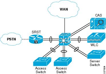
The basic modular switch School topology is shown in Figure 10-1.This design is based upon a collapsed core/distribution mode, and a Layer-2 access distribution model. In this type of design all of the IP subnets are defined on the 4500 modular switch, and access to these subnets is controlled by the VLANs that are trunked to the switches.
If desired a Layer-3 access switch model may be implemented, the physical topology does not change, and centrality of EtherChannel to the design does not change. The simplicity of the network design not only allows Layer-2 or Layer-3 access layers, it also allows a hybrid deployment. This allows the majority of clients on the switch use Layer-3 access features, but a group of legacy client are able to continue to use a Layer-2 network. This can be useful when migrating from clients that do not use IP, or rely heavily upon locally broadcast information to learn about services or devices on the network.
The 4500 modular core provides resilient connections to the access LAN switches, local server switch, WLC, and SRST Router through EtherChannel. The NAC Appliance does not support EtherChannel, and the two connections are used to connect to the trusted and untrusted interfaces of the CAS.
The WAN connection to the 4500 modular is a single connection
Figure 10-1 Stacked Switch School Schematic

Core/Distribution Virtual Interfaces
The following is an example configuration of the switch virtual interfaces (SVIs) configured on the core/distribution 4500 modular switch. This SVIs are trunked to the access switches as required, and access to the VLANs are controlled by the switchport trunk allowed vlan command applied on the port channels. The same basic configuration is used for the server switch.
interface Vlan101
description Connected to cr35_2960_Dept_1_VLAN
dampening
ip address 10.127.0.1 255.255.255.192
ip helper-address 10.125.31.2
no ip redirects
no ip unreachables
ip pim sparse-mode
load-interval 30
!
interface Vlan102
description Connected to cr35_2960_Dept_2_VLAN
dampening
ip address 10.127.0.65 255.255.255.192
ip helper-address 10.125.31.2
no ip redirects
no ip unreachables
ip pim sparse-mode
load-interval 30
!
...
!
interface Vlan110
description Connected to cr35_2960_Dept_10_VLAN
dampening
ip address 10.127.2.65 255.255.255.192
ip helper-address 10.125.31.2
no ip redirects
no ip unreachables
ip pim sparse-mode
load-interval 30
Example Port Channel Configuration
The following are examples of the port channel configuration on core/distribution 4500 modular switch and an example access switch. A similar configuration would be applied to each access switch connection with the same or different VLANs as required. From an IP routing or services level there is no requirement to span the same VLAN to multiple switches, but if there is a requirement to support legacy protocols such as AppleTalk at the school these AppleTalk VLANs can be easily spanned to different access switches as required
Example 4500 Modular Switch Port Channel Configuration
interface Port-channel11
description Connected to cr35-2960-SS1
switchport
switchport trunk encapsulation dot1q
switchport trunk native vlan 802
switchport trunk allowed vlan 101-110
switchport mode trunk
logging event link-status
load-interval 30
carrier-delay msec 0
qos trust dscp
Example 2960 Port Channel Configuration
interface Port-channel1
description Connected to cr35-4507-SS1
switchport trunk native vlan 802
switchport trunk allowed vlan 101-110,201
switchport mode trunk
ip arp inspection trust
load-interval 30
carrier-delay msec 0
hold-queue 2000 in
hold-queue 2000 out
ip dhcp snooping trust
WLC Connection
The WLC Connection to the core/distribution stack is fundamentally the same as an access switch connection, with different VLANs, and the exception of using a different QoS trust mode, where the CoS values from the WLC, are trusted. The following is an example 4500 modular switch Port Channel configuration:
Interface Port-channel12
description Connected to WLC-SS2
switchport trunk encapsulation dot1q
switchport trunk native vlan 802
switchport trunk allowed vlan 111-120
switchport mode trunk
load-interval 30
carrier-delay msec 0
ip dhcp snooping trust
NAC CAS Connection
The NAC CAS connection to the core/distribution switch. This is not an EtherChannel connection, but two switch ports are consumed. The two ports consist of a untrusted port for connecting client VLANs to the CAS prior to them completing the NAC process, and a trusted port that connects the NAS to the client VLANs used once clients have successfully completed the NAC process. The two, trusted and untrusted, ports are required even if OOB NAC is used, as the CAS requires access to the trusted VLANs during the NAC process. The following is an example of the configuration.
Core/Distribution NAC CAS Configuration
interface GigabitEthernet1/0/4
 description NAC Trusted Eth0
 switchport trunk encapsulation dot1q
 switchport trunk allowed vlan 48,57,62
 switchport mode trunk
 spanning-tree portfast trunk
!
interface GigabitEthernet1/0/5
!
interface GigabitEthernet1/0/6
!
interface GigabitEthernet1/0/7
!
interface GigabitEthernet1/0/8
 description NAC Untrusted Eth1
 switchport trunk encapsulation dot1q
 switchport trunk allowed vlan 61,248,257
 switchport mode trunk
 spanning-tree portfast trunk
SRST Connection Sample Configuration
The SRST connection to the core/distribution is another EtherChannel connection. The differences between the SRST connection and the access switch connections are that a trunk connection is not required, and that the SRST interfaces are router interfaces, requiring a slightly different connection. The following is an example of the configuration.
WAN Connection
The WAN connection is a single port connection from the core/distribution switch, and therefore there is no EtherChannel. The key component in the WAN connection configuration is the QoS implementation, that provides traffic shaping and limiting on this interface to ensure that the voice and video are given appropriate priority, but do not starve other applications of the throughput. An example of the WAN connection configuration is shown below.
WAN Port Sample Configuration—Core/Distribution
interface GigabitEthernet3/0/52
description Connected to MetroE-Core
switchport trunk encapsulation dot1q
switchport trunk native vlan 801
switchport trunk allowed vlan 650
switchport mode trunk
load-interval 30
carrier-delay msec 0
srr-queue bandwidth shape 35 15 25 25
srr-queue bandwidth limit 10
priority-queue out
mls qos trust dscp
no cdp enable
spanning-tree portfast trunk
spanning-tree bpdufilter enable
hold-queue 2000 in
hold-queue 2000 out
interface Vlan650
dampening
ip address 10.126.1.99 255.255.255.254
no ip redirects
no ip unreachables
ip pim sparse-mode
ip authentication mode eigrp 100 md5
ip authentication key-chain eigrp 100 eigrp-key
ip summary-address eigrp 100 10.127.112.0 255.255.248.0 5
load-interval 30
hold-queue 2000 in
hold-queue 2000 out
Small School—Stacked Switch Design
The basic stacked switch school topology is shown in Figure 10-2.This design is based upon a collapsed core/distribution mode, and a Layer-2 access distribution model. In this type of design, all of the IP subnets are defined on the 3750 stacked switch, and access to these subnets is controlled by the VLANs that are trunked to the switches.
The 3750 stackwise core provides resilient connections to the access LAN switches, local server switch, WLC, and SRST router through EtherChannel. The NAC Appliance does not support EtherChannel, and the two connections are used to connect to the trusted and untrusted interfaces of the CAS. The WAN connection to the 3750 stack is a single Ethernet connection.
Figure 10-2 Stacked Switch School Schematic
Below is an example configuration of the SVIs configured on the core/distribution 3750 stack. These SVIs are trunked to the access switches as required, and access to the VLANs are controlled by the switchport trunk allowed vlan command applied on the port channels. The same basic configuration is used for the server switch.
Core/Distribution Virtual Interfaces
Example Port Channel Configuration
The following example shows an example of the port channel configuration on core/distribution 3750 stack and an example access switch. A similar configuration would be applied to each access switch connection with the same or different VLANs as required. From an IP routing or services level there is no requirement to span the same VLAN to multiple switches, but if there is a requirement to support legacy protocols such as AppleTalk at the school these AppleTalk VLANs can be easily spanned to different access switches as required.
WLC Connection
The WLC connection to the core/distribution stack is fundamentally the same as an access switch connection, with different VLANs, and the exception of using a different QoS trust mode, where the CoS values from the WLC, are trusted. The following is an example of the configuration.
Example 3750 Stack Port Channel Configuration
Interface Port-channel12
description Connected to 2960-SS2
switchport trunk encapsulation dot1q
switchport trunk native vlan 802
switchport trunk allowed vlan 111-120
switchport mode trunk
load-interval 30
carrier-delay msec 0
ip dhcp snooping trust
interface GigabitEthernet1/0/48
description Connected to WLC-SS2
switchport trunk encapsulation dot1q
switchport trunk native vlan 802
switchport trunk allowed vlan 110-120
switchport mode trunk
load-interval 30
carrier-delay msec 0
srr-queue bandwidth share 1 30 35 5
priority-queue out
udld port

mls qos trust coschannel-group 11 mode active
spanning-tree guard root
!
interface GigabitEthernet3/0/48
description Connected to WLC-SS2
switchport trunk encapsulation dot1q
switchport trunk native vlan 802
switchport trunk allowed vlan 110-110,
switchport mode trunk
load-interval 30
carrier-delay msec 0
srr-queue bandwidth share 1 30 35 5
priority-queue out
udld port
mls qos trust coschannel-group 11 mode active
spanning-tree guard root
NAC CAS Connection
The NAC CAS connection to the core/distribution switch. This is not an EtherChannel connection, but two switch ports are consumed. The two ports consist of a untrusted port for connecting client VLANs to the CAS prior to them completing the NAC process, and a trusted port that connects the NAS to the client VLANs used once clients have successfully completed the NAC process. The two, trusted and untrusted, ports are required even if OOB NAC is used, as the CAS requires access to the trusted VLANs during the NAC process. The following is an example of the configuration.
Core/Distribution NAC CAS Configuration
interface GigabitEthernet1/0/4
 description NAC Trusted Eth0
 switchport trunk encapsulation dot1q
 switchport trunk allowed vlan 48,57,62
 switchport mode trunk
 spanning-tree portfast trunk
!
interface GigabitEthernet1/0/5
!
interface GigabitEthernet1/0/8
 description NAC Untrusted Eth1
 switchport trunk encapsulation dot1q
 switchport trunk allowed vlan 61,248,257
 switchport mode trunk
 spanning-tree portfast trunk
SRST Connection
The SRST connection to the core/distribution is another EtherChannel connection. The differences between the SRST connection and the access switch connections are that a trunk connection is not required, and that the SRST interfaces are router interfaces, requiring a slightly different connection. The following is an example of the configuration.
WAN Connection
The WAN connection is a single port connection from the core/distribution switch, and therefore there is no EtherChannel. The key component in the WAN connection configuration is the QoS implementation, that provides traffic shaping and limiting on this interface to ensure that the Voice and Video are given appropriate priority, but do not starve other applications of the throughput. An example of the WAN connection configuration is shown below.
interface GigabitEthernet3/0/52
description Connected to MetroE-Core
switchport trunk encapsulation dot1q
switchport trunk native vlan 801
switchport trunk allowed vlan 650
switchport mode trunk
load-interval 30
carrier-delay msec 0
srr-queue bandwidth shape 35 15 25 25
srr-queue bandwidth limit 10
priority-queue out
mls qos trust dscp
no cdp enable
spanning-tree portfast trunk
spanning-tree bpdufilter enable
hold-queue 2000 in
hold-queue 2000 out
interface Vlan650
dampening
ip address 10.126.1.99 255.255.255.254
no ip redirects
no ip unreachables
ip pim sparse-mode
ip authentication mode eigrp 100 md5
ip authentication key-chain eigrp 100 eigrp-key
ip summary-address eigrp 100 10.127.112.0 255.255.248.0 5
load-interval 30
hold-queue 2000 in
hold-queue 2000 out
 Feedback