- Connecting Network Cables
- Preparing Cisco UCS FI Manager and Configure Manager
- Cisco Nexus Plug-in for OpenStack Networking
- Creating OpenStack Setup on Nexus Plug-in Based Topology
Configuration Guidelines
The following sections define the details of configuring RHEL OpenStack Platform architecture on the Cisco UCS platform.
2.![]() Preparing Cisco UCS FI Manager and Configure Manager
Preparing Cisco UCS FI Manager and Configure Manager
3.![]() Cisco Nexus Plug-in for OpenStack Networking
Cisco Nexus Plug-in for OpenStack Networking
4.![]() Creating OpenStack Setup on Nexus Plug-in Based Topology
Creating OpenStack Setup on Nexus Plug-in Based Topology
5.![]() Configuring the Foreman Server
Configuring the Foreman Server
Connecting Network Cables
See the Cisco UCS FI, FEX, and C-series server configuration guide for details on mounting hardware on the rack. Figure 4-1 show three levels of architectural connectivity details covered in this document.
1.![]() Upstream Connectivity (shown in purple)
Upstream Connectivity (shown in purple)
2.![]() FIs to Fabric Extenders links (shown in blue)
FIs to Fabric Extenders links (shown in blue)
3.![]() Fabric Extenders to C220M3 server links (shown in green)
Fabric Extenders to C220M3 server links (shown in green)
Figure 4-1 Detailed Connectivity Diagram of the Architecture

Table 4-1 details cable connectivity for the architecture.
|
|
|
|
|
|
|
|---|---|---|---|---|---|
Figure 4-1 shows only one example C220M3 server, but all the rack servers (compute as well as storage nodes) connect in the similar manner.
For upstream connectivity, a pair of Nexus series switches is recommended. In that case, multiple UCS domains can connect to a pair of Nexus switches to provide highly available, scalable network. Virtual Port-Channel is recommended between Nexus series switches and FIs to reduce network instability during reboot of any of the switches or FIs.
Connect all cables as outlined in preparation for configuring the storage array and Cisco UCS Manager.
Preparing Cisco UCS FI Manager and Configure Manager
Configuring Cisco UCS FIs and Cisco UCS Manager includes the following procedures.
1.![]() Initial Configuration of Cisco UCS FIs
Initial Configuration of Cisco UCS FIs
2.![]() Configuration for Server Discovery
Configuration for Server Discovery
3.![]() Upstream/ Global Network Configuration
Upstream/ Global Network Configuration
5.![]() Configure Server Pool and Qualifying Policy
Configure Server Pool and Qualifying Policy
6.![]() Configure Service Profile Template
Configure Service Profile Template
7.![]() Instantiate Service Profiles from the Service Profile Template
Instantiate Service Profiles from the Service Profile Template
Initial Configuration of Cisco UCS FIs
At this point of time, the Cisco UCS FIs, FEX, and Blade Servers or Rack Servers must be mounted on the rack and appropriate cables must be connected. Two 100 Mbps Ethernet cables must be connected between two FIs for management pairing. Two redundant power supplies are provided per FI, it is highly recommended that both the power supplies are plugged in, ideally drawing power from two different power strips. Connect mgmt0 interfaces of each FI to the infrastructure network, and put the switch port connected to FI in access mode with access VLAN as management VLAN.
Perform the following procedure to initialize the FI configuration.
Step 1![]() Attach the RJ-45 serial console cable to the first FI, and connect the other end to the serial port of the laptop.
Attach the RJ-45 serial console cable to the first FI, and connect the other end to the serial port of the laptop.
Step 2![]() Configure the password for the admin account, fabric ID A, UCS system name, management IP address, subnet mask and default gateway and cluster IP address (or UCS Manager Virtual IP address), as the initial configuration script walks you through the configuration (Figure 4-2).
Configure the password for the admin account, fabric ID A, UCS system name, management IP address, subnet mask and default gateway and cluster IP address (or UCS Manager Virtual IP address), as the initial configuration script walks you through the configuration (Figure 4-2).
Step 3![]() Save the configuration, which will take you to the Cisco UCS Manager CLI login prompt.
Save the configuration, which will take you to the Cisco UCS Manager CLI login prompt.
Figure 4-2 Initial Configurations of Cisco UCS Fabric Interconnect

Step 4![]() Disconnect the RJ-45 serial console from the FI just configured and attach it to the other FI. The other FI would detect that its peer has been configured, and will prompt to join the cluster. Only information you need to provide is the FI specific management IP address, subnet mask, and default gateway. Save the configuration (Figure 4-3).
Disconnect the RJ-45 serial console from the FI just configured and attach it to the other FI. The other FI would detect that its peer has been configured, and will prompt to join the cluster. Only information you need to provide is the FI specific management IP address, subnet mask, and default gateway. Save the configuration (Figure 4-3).
Figure 4-3 Configuring Peer to a Fabric Interconnect

Step 5![]() Once the initial configurations on both FIs are complete, disconnect the serial console cable. The Cisco UCS Manager will now be accessible through web interface (https://<cums-virtual-ip>/) or SSH. Connect to the Cisco UCS Manager using SSH, and see the HA status. Since there is a common device connected between the two FIs (a rack server or blade server chassis), the status shows HA NOT READY. You must see both FI A and FI B in the Up state as shown in Figure 4-4.
Once the initial configurations on both FIs are complete, disconnect the serial console cable. The Cisco UCS Manager will now be accessible through web interface (https://<cums-virtual-ip>/) or SSH. Connect to the Cisco UCS Manager using SSH, and see the HA status. Since there is a common device connected between the two FIs (a rack server or blade server chassis), the status shows HA NOT READY. You must see both FI A and FI B in the Up state as shown in Figure 4-4.
Figure 4-4 Cisco UCS Fabric Interconnect—Cluster State

Configuration for Server Discovery
All the Ethernet ports of FIs are unconfigured and shutdown by default. You need to classify these ports as server facing ports, directly attached storage array facing ports, and uplink ports.
Perform the following procedure to configure the ports for proper server auto-discovery:
Step 1![]() To configure chassis discovery policy that specifies server side connectivity, using a web browser, access the Cisco UCS Manager from the management virtual IP address and download the Java applet to launch the Cisco UCS Manager GUI.
To configure chassis discovery policy that specifies server side connectivity, using a web browser, access the Cisco UCS Manager from the management virtual IP address and download the Java applet to launch the Cisco UCS Manager GUI.
Step 2![]() Click Equipment tab in the left pane, and then the Policies tab in the right pane. In Chassis Discovery Policy, For Actions field choose 2 Link. Two links represent the two 10 GE links that are connected between FI and FEX per fabric. Change Link Grouping Preference to Port Channel for better bandwidth utilization and link level high-availability, as shown in Figure 4-5. Save the changes.
Click Equipment tab in the left pane, and then the Policies tab in the right pane. In Chassis Discovery Policy, For Actions field choose 2 Link. Two links represent the two 10 GE links that are connected between FI and FEX per fabric. Change Link Grouping Preference to Port Channel for better bandwidth utilization and link level high-availability, as shown in Figure 4-5. Save the changes.
Figure 4-5 Configuring Chassis Discovery Policy

Step 3![]() Identify ports connected to the Chassis or FEX per FI basis. Click the Equipment tab, expand Fabric Interconnects, choose an FI, for example, Fabric Interconnect A, click Unconfigured Ethernet Ports, and select the two ports connected to the FEX-A. Right-click, and choose Configure as Server Port. Click Yes on the confirmation pop-up window (Figure 4-6).
Identify ports connected to the Chassis or FEX per FI basis. Click the Equipment tab, expand Fabric Interconnects, choose an FI, for example, Fabric Interconnect A, click Unconfigured Ethernet Ports, and select the two ports connected to the FEX-A. Right-click, and choose Configure as Server Port. Click Yes on the confirmation pop-up window (Figure 4-6).
Figure 4-6 Configuring Ethernet Ports as Server Ports

Step 4![]() Repeat step 3 for the other FI as well.
Repeat step 3 for the other FI as well.
Step 5![]() Once server ports are configured on both FIs, the Chassis or FEX auto-discovery gets started. In case of FEX, after the deep discovery of FEX is complete, you will see two Fabric Extenders in the Equipment tab with overall status shown as Operable (Figure 4-7).
Once server ports are configured on both FIs, the Chassis or FEX auto-discovery gets started. In case of FEX, after the deep discovery of FEX is complete, you will see two Fabric Extenders in the Equipment tab with overall status shown as Operable (Figure 4-7).
Figure 4-7 Overall Status of FEX After Auto-Discovery

Step 6![]() After the Chassis and FEX auto-discovery, the Blade Server and Rack Server auto-discovery starts, respectively. As and when the servers are discovered, they get added in the Equipment tab with overall status shown as Unassociated with an availability state as Available, and discovery state as Complete (Figure 4-8).
After the Chassis and FEX auto-discovery, the Blade Server and Rack Server auto-discovery starts, respectively. As and when the servers are discovered, they get added in the Equipment tab with overall status shown as Unassociated with an availability state as Available, and discovery state as Complete (Figure 4-8).
Figure 4-8 Overall Status of Rack Servers After Discovery

Step 7![]() Once all the servers are discovered, select Equipment > Rack-Mounts > Servers to view a summary (Figure 4-9).
Once all the servers are discovered, select Equipment > Rack-Mounts > Servers to view a summary (Figure 4-9).
Figure 4-9 Summary of Rack Servers After the Discovery

Upstream/ Global Network Configuration
This section lists a few upstream/ global network configuration:
Perform the following procedure to configure upstream/ global networks.
Step 1![]() Click the LAN tab, expand LAN Cloud and right-click on VLANs and Click Create VLANs (Figure 4-10).
Click the LAN tab, expand LAN Cloud and right-click on VLANs and Click Create VLANs (Figure 4-10).

Step 2![]() Enter the name of the VLAN and assign a VLAN ID. Make sure the default option Common/Global radio button is selected. Click OK to deploy the VLAN (Figure 4-11).
Enter the name of the VLAN and assign a VLAN ID. Make sure the default option Common/Global radio button is selected. Click OK to deploy the VLAN (Figure 4-11).
Figure 4-11 Entering Details of VLAN

Step 3![]() Repeat the steps for “RHOS-Data” and various tenant VLANs.
Repeat the steps for “RHOS-Data” and various tenant VLANs.
Step 4![]() To configure Uplink ports connected to the infrastructure network, click the Equipment tab, expand Fabric Interconnects, choose a particular FI, expand Expansion Module 2 (this may vary depending on which port you have chosen as uplink port), right-click on the Ethernet port, and choose Configure as Uplink Port (Figure 4-12). Repeat this step for all the uplink ports on each FI.
To configure Uplink ports connected to the infrastructure network, click the Equipment tab, expand Fabric Interconnects, choose a particular FI, expand Expansion Module 2 (this may vary depending on which port you have chosen as uplink port), right-click on the Ethernet port, and choose Configure as Uplink Port (Figure 4-12). Repeat this step for all the uplink ports on each FI.
Figure 4-12 Configuring Ethernet Ports as Uplink Ports

Configure Identifier Pools
In this section, we would configure following identifier pools used by service profile:
Perform the following procedure to configure identifier pools.
Step 1![]() From the Servers tab, expand Servers > Pools > root, and right-click on UUID Suffix pools and click Create UUID Suffix Pool (Figure 4-13).
From the Servers tab, expand Servers > Pools > root, and right-click on UUID Suffix pools and click Create UUID Suffix Pool (Figure 4-13).
Figure 4-13 Creating UUID Suffix Pool

Step 2![]() Enter the name and description to the UUID suffix pool (Figure 4-14). Keep other configuration as default.
Enter the name and description to the UUID suffix pool (Figure 4-14). Keep other configuration as default.
Figure 4-14 Details for Creating UUID Suffix Pool

Step 3![]() Click (+Add) to add UUID block (Figure 4-15).
Click (+Add) to add UUID block (Figure 4-15).

Step 4![]() Specify the beginning of the UUIDs, and have a large size of UUID block to accommodate future expansion (Figure 4-16).
Specify the beginning of the UUIDs, and have a large size of UUID block to accommodate future expansion (Figure 4-16).
Figure 4-16 Specifying Block Size

Step 5![]() Click OK and then Finish to deploy UUID pool.
Click OK and then Finish to deploy UUID pool.
Step 6![]() Click the LAN tab, expand LAN > Pools > root, right-click on MAC Pools and select Create MAC Pool (Figure 4-17).
Click the LAN tab, expand LAN > Pools > root, right-click on MAC Pools and select Create MAC Pool (Figure 4-17).

Step 7![]() Enter the name and description for MAC pool and click Next (Figure 4-18).
Enter the name and description for MAC pool and click Next (Figure 4-18).
Figure 4-18 Details for Creating MAC Pool

Step 8![]() Click (+Add) to add MAC pool block (Figure 4-19).
Click (+Add) to add MAC pool block (Figure 4-19).
Figure 4-19 Adding MAC Address

Step 9![]() Enter the initial MAC address and size of the block. As always, provide large number of MAC addresses to accommodate future expansion. Six (6) MAC addresses per server are required.
Enter the initial MAC address and size of the block. As always, provide large number of MAC addresses to accommodate future expansion. Six (6) MAC addresses per server are required.
Step 10![]() Create the management IP address block for KVM access of the servers (Figure 4-20). The default pool for server CIMC management IP addresses are created with the name ext-mgmt. From the LAN tab, expand LAN > Pools > root > IP Pools > IP Pool ext-mgmt, and click the Create Block of IP addresses link in the right pane.
Create the management IP address block for KVM access of the servers (Figure 4-20). The default pool for server CIMC management IP addresses are created with the name ext-mgmt. From the LAN tab, expand LAN > Pools > root > IP Pools > IP Pool ext-mgmt, and click the Create Block of IP addresses link in the right pane.
Figure 4-20 Creating IP Address Block

Step 11![]() Enter the initial IP address, size of the pool, default gateway and subnet mask (Figure 4-21).). Click OK to deploy the configuration. IP addresses are assigned to various Rack-Mount server CIMC management access from this block.
Enter the initial IP address, size of the pool, default gateway and subnet mask (Figure 4-21).). Click OK to deploy the configuration. IP addresses are assigned to various Rack-Mount server CIMC management access from this block.
Figure 4-21 Specifying the IP Address Block Size

Configure Server Pool and Qualifying Policy
Creation and policy based auto-population of server pool can be sub-divided into the following tasks:
2.![]() Creation of server pool policy qualification
Creation of server pool policy qualification
3.![]() Creation of server pool policy
Creation of server pool policy
Perform the following procedure to complete these tasks.
Step 1![]() From the Servers tab, expand Servers > Pools > root, right-click on Server Pools and choose Create Server Pool (Figure 4-22).
From the Servers tab, expand Servers > Pools > root, right-click on Server Pools and choose Create Server Pool (Figure 4-22).
Figure 4-22 Creating Server Pools

Step 2![]() Enter the name of the server pool in the Name field, and click Next (Figure 4-23).
Enter the name of the server pool in the Name field, and click Next (Figure 4-23).
Figure 4-23 Entering Details in the Create Server Pool Wizard

Step 3![]() Click Finish to create the empty server pool. We would add the compute resources to this pool dynamically, based on policy (Figure 4-24).
Click Finish to create the empty server pool. We would add the compute resources to this pool dynamically, based on policy (Figure 4-24).
Figure 4-24 Adding Servers in the Create Server Pool Wizard

Step 4![]() From the Servers tab, expand Servers > Policies > root, right-click on Server Pool Policy Qualifications and choose Create Server Pool Policy Qualification (Figure 4-25).
From the Servers tab, expand Servers > Policies > root, right-click on Server Pool Policy Qualifications and choose Create Server Pool Policy Qualification (Figure 4-25).
Figure 4-25 Creating Server Pool Policy Qualification

Step 5![]() Enter the name for the server policy qualification criterion as MinStorage4TB in the Name field. In the left pane under Actions choose Create Memory Qualifications to server policy qualification criterion. Choose storage qualification criterion and provide minimum storage capacity as 4194304 MB (for 4 TB storage) as shown in Figure 4-26. Click OK twice to save the storage qualification.
Enter the name for the server policy qualification criterion as MinStorage4TB in the Name field. In the left pane under Actions choose Create Memory Qualifications to server policy qualification criterion. Choose storage qualification criterion and provide minimum storage capacity as 4194304 MB (for 4 TB storage) as shown in Figure 4-26. Click OK twice to save the storage qualification.
Figure 4-26 Creating Memory Qualification for Storage Nodes

Step 6![]() Similarly, to create qualification for compute nodes, enter the name as MinCore20 in the server policy qualification criterion. Choose CPU/Cores qualification criterion and provide minimum cores as 20 as shown in Figure 36. Click OK twice to save the compute node qualification (Figure 4-27).
Similarly, to create qualification for compute nodes, enter the name as MinCore20 in the server policy qualification criterion. Choose CPU/Cores qualification criterion and provide minimum cores as 20 as shown in Figure 36. Click OK twice to save the compute node qualification (Figure 4-27).

Note This is just an example criterion, you can choose a criterion that suites your requirement.
Figure 4-27 Creating Memory Qualification for Compute Nodes

Step 7![]() From the Servers tab, expand Servers > Policies > root, right-click on Server Pool Policies and choose Create Server Pool Policy (Figure 4-28).
From the Servers tab, expand Servers > Policies > root, right-click on Server Pool Policies and choose Create Server Pool Policy (Figure 4-28).
Figure 4-28 Creating Server Pool Policy

Step 8![]() Enter the name as OS-Compute-Nodes in the server pool policy. Choose recently created Target Pool and Qualification for compute nodes. Click OK to deploy the configuration (Figure 4-29).
Enter the name as OS-Compute-Nodes in the server pool policy. Choose recently created Target Pool and Qualification for compute nodes. Click OK to deploy the configuration (Figure 4-29).
Figure 4-29 Details for Creating Server Pool Policy—Compute

Step 9![]() Similarly, create an other Server Pool Policy for storage nodes. Enter the name as OS-Storage-Nodes. Choose recently created Target Pool and Qualification for storage nodes. Click OK to deploy the configuration (Figure 4-30).
Similarly, create an other Server Pool Policy for storage nodes. Enter the name as OS-Storage-Nodes. Choose recently created Target Pool and Qualification for storage nodes. Click OK to deploy the configuration (Figure 4-30).
Figure 4-30 Details for Creating Server Pool Policy—Storage

Step 10![]() If you go back to the server pool created in step 1 above and click the Servers tab on right pane, you will see that all the compute resources that meet the qualification criteria are dynamically added to the server pool. Figure 4-31shows all the dynamically added resources in the server pool.
If you go back to the server pool created in step 1 above and click the Servers tab on right pane, you will see that all the compute resources that meet the qualification criteria are dynamically added to the server pool. Figure 4-31shows all the dynamically added resources in the server pool.
Figure 4-31 Qualified Compute Resources Automatically Added to the Server Pool

Configure Service Profile Template
At this point, we are ready to create service profile template, from which we can instantiate individual service profiles later.
We need to create three service profile templates:
1.![]() RHOS-A: For compute nodes with system VNICs on fabric A
RHOS-A: For compute nodes with system VNICs on fabric A
2.![]() RHOS-B: For compute nodes with system VNICs on fabric B
RHOS-B: For compute nodes with system VNICs on fabric B
3.![]() RHOS-Storage: For storage nodes
RHOS-Storage: For storage nodes
Perform the following procedure to create these service profile templates.
Step 1![]() From the Servers tab. Expand Servers > Service Profile Templates, right-click on service profile templates and choose Create Service Profile Template (Figure 4-32).
From the Servers tab. Expand Servers > Service Profile Templates, right-click on service profile templates and choose Create Service Profile Template (Figure 4-32).
Figure 4-32 Creating Service Profile Template

Step 2![]() Enter the service profile template name in the name field, keep the type as Initial Template, and choose UUID pool for UUID assignment (Figure 4-33).
Enter the service profile template name in the name field, keep the type as Initial Template, and choose UUID pool for UUID assignment (Figure 4-33).
Figure 4-33 Creating Service Profile Template—Entering Details

Step 3![]() Click the Expert radio button for configure LAN connectivity. Click to create a vNIC (Figure 4-34).
Click the Expert radio button for configure LAN connectivity. Click to create a vNIC (Figure 4-34).
Figure 4-34 Creating Service Profile Template—LAN Configuration Details

Step 4![]() Create a system vNIC for fabric A. Enter System as the vNIC name, choose the MAC pool created in section D, click the radio button fabric A for fabric ID, check the check box Infra for VLANs and click the native VLAN radio button. For Adapter Policy field, choose Linux (Figure 4-35).
Create a system vNIC for fabric A. Enter System as the vNIC name, choose the MAC pool created in section D, click the radio button fabric A for fabric ID, check the check box Infra for VLANs and click the native VLAN radio button. For Adapter Policy field, choose Linux (Figure 4-35).
Figure 4-35 Creating a System vNIC

Step 5![]() Similarly, create an other vNIC for VM data traffic. Enter Data as the vNIC name, choose the MAC pool created earlier, click the radio button fabric B for fabric ID, check the Enable Failover check box. check the check boxes RHOS-Data and various tenant VLANs with RHOS-Data as the native VLAN. For Adapter Policy field, choose Linux (Figure 4-36).
Similarly, create an other vNIC for VM data traffic. Enter Data as the vNIC name, choose the MAC pool created earlier, click the radio button fabric B for fabric ID, check the Enable Failover check box. check the check boxes RHOS-Data and various tenant VLANs with RHOS-Data as the native VLAN. For Adapter Policy field, choose Linux (Figure 4-36).
Figure 4-36 Creating vNIC for VM Data Traffic

Step 6![]() In the Storage window, for Local Storage, choose Create a Specific Storage Policy option from the drop-down list. For mode choose, RAID 6 Stripped Dual Parity option from the drop-down list. click the No vHBA radio button for SAN connectivity (Figure 4-37).
In the Storage window, for Local Storage, choose Create a Specific Storage Policy option from the drop-down list. For mode choose, RAID 6 Stripped Dual Parity option from the drop-down list. click the No vHBA radio button for SAN connectivity (Figure 4-37).
Figure 4-37 Creating Service Profile Template—Storage Configuration Details

Step 7![]() Keep default configurations in Zoning and vNIC/vHBA Placement windows by simply clicking Next.
Keep default configurations in Zoning and vNIC/vHBA Placement windows by simply clicking Next.
Step 8![]() In the Server Boot Order window, click Create Boot Policy (Figure 4-38).
In the Server Boot Order window, click Create Boot Policy (Figure 4-38).
Figure 4-38 Creating Service Profile Template—Configuring Boot Order

Step 9![]() In the Create Boot Policy window, enter the name as Local in the Name Field, check the Reboot on Boot Order Change checkbox, firstly, click Add CD-ROM and then click Add Local Disk under Local Devices on left pane of the window. Click OK to create the boot policy (Figure 4-39).
In the Create Boot Policy window, enter the name as Local in the Name Field, check the Reboot on Boot Order Change checkbox, firstly, click Add CD-ROM and then click Add Local Disk under Local Devices on left pane of the window. Click OK to create the boot policy (Figure 4-39).
Figure 4-39 Creating Boot Order Policy

Step 10![]() Now in the Server Boot order window, for Boot Policy, choose Local from the drop-down list. Click Next (Figure 4-40).
Now in the Server Boot order window, for Boot Policy, choose Local from the drop-down list. Click Next (Figure 4-40).
Figure 4-40 Configuring the Server Boot Order

Step 11![]() Click Next to go to the Maintenance Policy window. Keep all the fields at default and click Next to continue to Server Assignment window. For Pool Assignment, choose the OpenStack-ComputeNodes created earlier. Click Next (Figure 4-41).
Click Next to go to the Maintenance Policy window. Keep all the fields at default and click Next to continue to Server Assignment window. For Pool Assignment, choose the OpenStack-ComputeNodes created earlier. Click Next (Figure 4-41).
Figure 4-41 Creating Service Profile Template—Configuring Server Assignment

Step 12![]() In the Operation Policies window, keep all the fields at default, and click Finish to deploy the Service Profile Template (Figure 4-42).
In the Operation Policies window, keep all the fields at default, and click Finish to deploy the Service Profile Template (Figure 4-42).
Figure 4-42 Creating Service Profile Template—Restore Default Settings for Operational Policy

Step 13![]() We can leverage the RHOS-A service profile template to create templates for RHOS-B and RHOS-Storage. Select the recently created Service Template RHOS-A by expanding Service Profile Template in the Servers tab. Servers > Service Profile Templates > root, right-click on Service Template RHOS-A and click Create a Clone (Figure 4-43).
We can leverage the RHOS-A service profile template to create templates for RHOS-B and RHOS-Storage. Select the recently created Service Template RHOS-A by expanding Service Profile Template in the Servers tab. Servers > Service Profile Templates > root, right-click on Service Template RHOS-A and click Create a Clone (Figure 4-43).
Figure 4-43 Cloning a Service Profile Template

Step 14![]() Enter the template name RHOS-B and for Org field, choose root from the drop-down list and click OK. This will create an identical service profile template, with the name RHOS-B (Figure 4-44).
Enter the template name RHOS-B and for Org field, choose root from the drop-down list and click OK. This will create an identical service profile template, with the name RHOS-B (Figure 4-44).
Figure 4-44 Cloning RHOS-B from RHOS-A

Step 15![]() The only change that we want to make in RHOS-B is to swap primary fabric IDs of the System and Data VNICs. Expand Service Template RHOS-B, expand vNICs and select vNIC Data and change the Fabric ID to Fabric A. Click Save Changes (Figure 4-45).
The only change that we want to make in RHOS-B is to swap primary fabric IDs of the System and Data VNICs. Expand Service Template RHOS-B, expand vNICs and select vNIC Data and change the Fabric ID to Fabric A. Click Save Changes (Figure 4-45).
Figure 4-45 Details of Service Template RHOS-B

Step 16![]() Similarly, go to System vNIC, and change its Fabric ID to Fabric B and click Save Changes.
Similarly, go to System vNIC, and change its Fabric ID to Fabric B and click Save Changes.
Step 17![]() Now repeat step 13 to clone Service Template RHOS-Storage from RHOS-A. Enter the name as RHOS-Storage and For Org, choose the option root from the drop-down list (Figure 4-46).
Now repeat step 13 to clone Service Template RHOS-Storage from RHOS-A. Enter the name as RHOS-Storage and For Org, choose the option root from the drop-down list (Figure 4-46).
Figure 4-46 Cloning RHOS-Storage form RHOS-A

Step 18![]() We need to edit the created Service Template RHOS-Storage. Select RHOS-Storage, click the Storage tab in the right pane, and click Change Local Disk Configuration Policy (Figure 4-47).
We need to edit the created Service Template RHOS-Storage. Select RHOS-Storage, click the Storage tab in the right pane, and click Change Local Disk Configuration Policy (Figure 4-47).
Figure 4-47 Changing Local Disk Configuration Policy for RHOS-Storage

Step 19![]() In the Change Local Disk Configuration Policy window, choose the option Any Configuration from the drop-down list for Mode. By selecting this option, Cisco UCS Manager will not alter any local disk configurations that were made off-line. We will expose individual disks as RAID0 configuration later. Click OK to save the changes (Figure 4-48).
In the Change Local Disk Configuration Policy window, choose the option Any Configuration from the drop-down list for Mode. By selecting this option, Cisco UCS Manager will not alter any local disk configurations that were made off-line. We will expose individual disks as RAID0 configuration later. Click OK to save the changes (Figure 4-48).
Figure 4-48 Changing Local Disk Configuration Policy

Step 20![]() From the Servers tab, expand root and select Service Template RHOS-Storage. Click the General tab on the right pane of the window, and click Associate with Server Pool (Figure 4-49).
From the Servers tab, expand root and select Service Template RHOS-Storage. Click the General tab on the right pane of the window, and click Associate with Server Pool (Figure 4-49).
Figure 4-49 Associating the Template with the Server Pool

Step 21![]() For Pool Assignment, choose the option OpenStack-StorageNodes from the drop-down list (Figure 4-50). Click OK to save the changes.
For Pool Assignment, choose the option OpenStack-StorageNodes from the drop-down list (Figure 4-50). Click OK to save the changes.
Figure 4-50 Associating Service Profile Template with the Server

Instantiate Service Profiles from the Service Profile Template
As a final step to configure Cisco UCS Manager, we need to instantiate service profiles from the service profile template created in Configure Service Profile Template.
Perform the following procedure to instantiate service profiles from the service profile template.
Step 1![]() From the Servers tab, expand Servers > Service profiles > root, and click the Create Service Profile from Template link in the right pane (Figure 4-51).
From the Servers tab, expand Servers > Service profiles > root, and click the Create Service Profile from Template link in the right pane (Figure 4-51).
Figure 4-51 Creating Service Profile from Template

Step 2![]() Enter the name as RHOS-A and for number of service profiles to be instantiated enter 3 and choose the service profile template from the drop-down list (Figure 4-52).
Enter the name as RHOS-A and for number of service profiles to be instantiated enter 3 and choose the service profile template from the drop-down list (Figure 4-52).
Figure 4-52 Details for Creating Service Profiles

Step 3![]() Repeat steps 1 and 2, for Service Template RHOS-B, with the same Name RHOS and same number of servers. Again, repeat steps 1 and 2 for Service Template RHOS-Storage. Enter the name as RHOS-Storage-Node, enter 2 for Number, and choose RHOS-Storage as service profile template from the drop-down list. Three service profiles are created in this example.
Repeat steps 1 and 2, for Service Template RHOS-B, with the same Name RHOS and same number of servers. Again, repeat steps 1 and 2 for Service Template RHOS-Storage. Enter the name as RHOS-Storage-Node, enter 2 for Number, and choose RHOS-Storage as service profile template from the drop-down list. Three service profiles are created in this example.
Step 4![]() Six service profiles for compute nodes and two service profiles for storage nodes are created in this example (Figure 4-53).
Six service profiles for compute nodes and two service profiles for storage nodes are created in this example (Figure 4-53).
Figure 4-53 Window Showing All the Service Profiles Created from the Template

Step 5![]() As the service profile template is assigned to a server pool, the service profiles instantiated from the template would be assigned to individual server resource from the server pool as far as they are available. You can select a given service profile to see its association state, and with which server it is associated (Figure 4-54).
As the service profile template is assigned to a server pool, the service profiles instantiated from the template would be assigned to individual server resource from the server pool as far as they are available. You can select a given service profile to see its association state, and with which server it is associated (Figure 4-54).
Figure 4-54 Status Details Of Service Profiles

Step 6![]() Eventually, all the four servers are associated. Click Servers in the Equipment tab to view a summary (Figure 4-55).
Eventually, all the four servers are associated. Click Servers in the Equipment tab to view a summary (Figure 4-55).
Figure 4-55 Summary of Service Profiles Showing Assigned State as Associated

Cisco Nexus Plug-in for OpenStack Networking
The following sections define the details of the Cisco Nexus plug-in for OpenStack networking.
3.![]() Multi-Homed Host Deployments
Multi-Homed Host Deployments
4.![]() Support for OpenStack Neutron Provider Networks
Support for OpenStack Neutron Provider Networks
5.![]() Cisco Nexus Plug-in and Modular Layer 2 Cisco Nexus Driver
Cisco Nexus Plug-in and Modular Layer 2 Cisco Nexus Driver
6.![]() Support for Cisco Nexus 3000, 5000, 6000, and 7000 Series Switches
Support for Cisco Nexus 3000, 5000, 6000, and 7000 Series Switches
Product Description
The Cisco Nexus® family of switches has been a staple in data centers since its introduction in 2008. The Cisco Nexus plug-in for OpenStack Neutron allows customers to easily build their infrastructure-as-a-service (IaaS) networks using the industry’s leading networking platform, delivering performance, scalability, and stability with the familiar manageability and control you expect from Cisco® technology.
The Cisco Nexus plug-in for OpenStack Neutron provides operational simplicity by enabling configuration of both physical and virtual switches deployed across multiple hosts. The updated plug-in for the OpenStack Havana release provides new features and flexibility for network connectivity of OpenStack clusters.
VLAN Programming
The Cisco Nexus plug-in for OpenStack can configure VLANs on Cisco Nexus switches through OpenStack Neutron. It efficiently and intelligently uses VLAN ID assignment on switch ports by provisioning and deprovisioning VLANs across switches as virtual machines connected to tenant networks are created and destroyed. Moreover, connectivity from the compute hosts to the physical network is trunked to allow traffic only from the VLANs configured on the host by the virtual switch.
Multi-Homed Host Deployments
Highly available OpenStack network configurations are now possible using virtual Port Channels (vPCs). The plug-in provisions and deprovisions tenant VLANs dynamically and efficiently on Cisco Nexus Port Channel interfaces. Hosts using vPCs can provide network high availability in the event of link failure and offer better overall link utilization. The ports connected to hosts are configured as vPC ports with the correct VLAN to provide tenant network isolation.
Support for OpenStack Neutron Provider Networks
The Cisco Nexus plug-in also supports the new OpenStack Neutron provider network extension APIs. Provider networks allow administrators to explicitly manage the relationship between OpenStack Neutron virtual networks and underlying physical mechanisms such as VLANs for virtual machine network connectivity. Using these APIs, the Cisco Nexus plug-in controls VLAN creation as well as trunking on the Cisco Nexus switch.
Cisco Nexus Plug-in and Modular Layer 2 Cisco Nexus Driver
OpenStack Neutron provides an extensible architecture that supports a variety of plug-ins for configuring physical networks. However, choosing a network plug-in restricts configuration of only that plug-in’s target technology. The Cisco plug-in architecture solved this problem in the OpenStack Grizzly release by enabling use of multiple plug-ins simultaneously. The Cisco plug-in accepts OpenStack Neutron API calls, and it directly configures Cisco Nexus switches as well as the virtual switch running on the hypervisor. Additionally, with the OpenStack Havana release, the Cisco plug-in added limited support (programming VLANs) for the Cisco Nexus driver in the Modular Layer 2 (ML2) OpenStack Neutron plug-in. This support enables configuration of Cisco Nexus switches using the ML2 Cisco Nexus type driver for deployments in which ML2 is the core OpenStack Neutron plug-in instead of the Cisco plug-in.
Support for Cisco Nexus 3000, 5000, 6000, and 7000 Series Switches
The Cisco Nexus plug-in provides a driver interface to communicate with Cisco Nexus switches. The driver uses the standard Network Configuration Protocol (Netconf) interface to send configuration requests to program the switches. It supports the Cisco Nexus 3000, 5000, 6000, and 7000 Series Switches, which run Cisco NX-OS Software.
Figure 1 shows how the Cisco Nexus plug-in configures both physical and virtual switching infrastructure, including programming of VLANs on Ethernet and Port Channel interfaces.
Creating OpenStack Setup on Nexus Plug-in Based Topology
The following sections define the details of creating an OpenStack setup on the Nexus plug-in topology.
2.![]() Prerequisites and Getting the Red Hat Enterprise Linux 6.5 ISO
Prerequisites and Getting the Red Hat Enterprise Linux 6.5 ISO
3.![]() Installation of the Build Node
Installation of the Build Node
6.![]() Installing Foreman Packages
Installing Foreman Packages
Foreman Installation
Foreman based installation for Red-Hat OpenStack Platform 4.0 requires the creation of a build-server. It acts as the puppet master, and provides PXE for servers that would be future nodes in the OpenStack setup.
Prerequisites and Getting the Red Hat Enterprise Linux 6.5 ISO
As a prerequisite you would require a red hat account and a Red Hat Enterprise Linux 6.5 ISO. If you do not already have Red Hat Enterprise Linux 6.5 ISO you can download it on a separate machine using the steps mentioned in this section below.
Step 1![]() Once you have an account with red hat, download the Red Hat Enterprise Linux 6.5 ISO Image (Figure 4-56).
Once you have an account with red hat, download the Red Hat Enterprise Linux 6.5 ISO Image (Figure 4-56).
Figure 4-56 Red Hat Customer Portal for Subscription Management and Software Downloads
Step 2![]() Under the section Red Hat Enterprise Linux click the download software link (Figure 4-57).
Under the section Red Hat Enterprise Linux click the download software link (Figure 4-57).
Figure 4-57 Download Options for Red Hat Enterprise Linux 6.5

Step 3![]() Click the link, Red Hat Enterprise Linux Server (v.6 for 64-bit x86_64). The image requires around 3.5 GBs of space on your local hard disk of the system you are using to download (Figure 4-58).
Click the link, Red Hat Enterprise Linux Server (v.6 for 64-bit x86_64). The image requires around 3.5 GBs of space on your local hard disk of the system you are using to download (Figure 4-58).
Figure 4-58 Download Page for Red Hat Enterprise Linux 6.5

Step 4![]() Click and download the Binary DVD ISO from this location.
Click and download the Binary DVD ISO from this location.
Installation of the Build Node
The downloaded ISO should be attached as a virtual media in Cisco UCS-CIMC/UCSM. Upon booting from the ISO, complete the install of Red Hat Enterprise Linux 6.5 on the server designated at the build-node. The installation can be completed using GUI based installer, which would be prompted open booting from the red hat Red Hat Enterprise Linux 6.5 ISO.
Once the base Red Hat Enterprise Linux 6.5 server is properly installed. Reboot the machine. You need to make below mentioned changes as a prerequisite before installing Foreman.
Configure the management network between the build node and the future OpenStack nodes. Configure one of the available Ethernet interface with an IP from the management network.
Puppet certificate signing uses the Fully Qualified Domain Name (FQDN); Hence, make sure that the system has a Fully Qualified Domain Name configured properly. Which means that appropriate entries under /etc/hosts and /etc/sysconfig/network should be done. To validate if the host name is properly set, confirm if the output of hostname –f yields a FQDN.
Subscribing to Red hat
Registration of the Red Hat Enterprise Linux 6.5 Server with red hat needs to be done to make packages and channels available to the Server. This can be done via Subscription manager or Classic RHN. Subscription Manager is the preferred method. Alternately, RHN Classic could also be used. Both the methods are described below. Only one method mentioned below should be applied for a given Red Hat Enterprise Linux server.
Using Subscription Manager
Perform the following procedure to use Subscription Manager for Red Hat Enterprise Linux 6.5 Server registration.
Step 1![]() If the setup is behind the proxy, edit the file /etc/rhsm/rhsm.conf and change the parameter proxy_hostname, proxy_port, proxy_user, and proxy_password with proxy details in your network.
If the setup is behind the proxy, edit the file /etc/rhsm/rhsm.conf and change the parameter proxy_hostname, proxy_port, proxy_user, and proxy_password with proxy details in your network.
Step 2![]() Register to the subscription manager using the subscription-manager register command.
Register to the subscription manager using the subscription-manager register command.
Step 3![]() Use the subscription-manager list command to locate the pool identifier of the Red Hat Enterprise Linux subscription.
Use the subscription-manager list command to locate the pool identifier of the Red Hat Enterprise Linux subscription.
Step 4![]() Use the subscription-manager attach command to attach the subscription identified in the previous step. The POOLID needs to be identified from the previous step that contains “Red Hat Openstack Platform” which should be used for this setup.
Use the subscription-manager attach command to attach the subscription identified in the previous step. The POOLID needs to be identified from the previous step that contains “Red Hat Openstack Platform” which should be used for this setup.
Step 5![]() Run the yum repolist command. This command ensures that the repository configuration file /etc/yum.repos.d/redhat.repo exists and is up to date.
Run the yum repolist command. This command ensures that the repository configuration file /etc/yum.repos.d/redhat.repo exists and is up to date.
Step 6![]() Once repository metadata has been downloaded and examined, the list of repositories enabled will be displayed, along with the number of available packages
Once repository metadata has been downloaded and examined, the list of repositories enabled will be displayed, along with the number of available packages
The output displayed may differ from that which appears when you run the yum repolist command on your system. In particular, the number of packages listed varies if or when additional packages are added to the rhel-6-server-rpms repository.
Step 7![]() Use either the subscription-manager or yum-config-manager commands to enable or disable the appropriate software repositories (channels). Unless already installed, you can use the following to install yum-config-manager:
Use either the subscription-manager or yum-config-manager commands to enable or disable the appropriate software repositories (channels). Unless already installed, you can use the following to install yum-config-manager:
For example, to ensure that the repository for Red Hat Enterprise Linux OpenStack Platform 3 (Grizzly) has been disabled, run:
Yum treats the values True and 1 as equivalent. As a result the output on your system may instead contain this string: enabled = 1
Step 8![]() Run the yum repolist command to ensure the repository configuration file /etc/yum.repos.d/redhat.repo exists and is up to date.
Run the yum repolist command to ensure the repository configuration file /etc/yum.repos.d/redhat.repo exists and is up to date.
Once repository metadata has been downloaded and examined, the current list of enabled repositories is displayed, along with the number of available packages.
Step 9![]() Use the yum-config-manager command to enable the Red Hat Enterprise Linux OpenStack Platform repository. Remember to use the repository name listed in the Red Hat Enterprise Linux OpenStack Platform Release Notes.
Use the yum-config-manager command to enable the Red Hat Enterprise Linux OpenStack Platform repository. Remember to use the repository name listed in the Red Hat Enterprise Linux OpenStack Platform Release Notes.
Step 10![]() Install the yum-plugin-priorities package. The yum-plugin-priorities package provides a yum plug-in allowing configuration of per-repository priorities.
Install the yum-plugin-priorities package. The yum-plugin-priorities package provides a yum plug-in allowing configuration of per-repository priorities.
Step 11![]() Use the yum-config-manager command to set the priority of the Red Hat Enterprise Linux OpenStack Platform software repository to 1. This is the highest priority value supported by the yum-plugin-priorities plug-in. Remember to use the repository name listed in the Red Hat Enterprise Linux OpenStack Platform Release Notes.
Use the yum-config-manager command to set the priority of the Red Hat Enterprise Linux OpenStack Platform software repository to 1. This is the highest priority value supported by the yum-plugin-priorities plug-in. Remember to use the repository name listed in the Red Hat Enterprise Linux OpenStack Platform Release Notes.
Step 12![]() Run the yum update command and reboot to ensure that the most up to date packages, including the kernel, are installed and running.
Run the yum update command and reboot to ensure that the most up to date packages, including the kernel, are installed and running.
You have successfully configured your system to receive Red Hat Enterprise Linux OpenStack Platform packages. You may use the yum repolist command to confirm the repository configuration again at any time.
Using Classic RHN (Red Hat Network)
Perform the following procedure to subscribe to the Red Hat Package Network if you are using the Classic RHN (Red Hat Network).
Step 1![]() If the setup is behind proxy, edit the file /etc/sysconfig/rhn/up2date and change the parameter enable_proxy from 0 to 1 and mention the proxy details next to the parameter httpProxy.
If the setup is behind proxy, edit the file /etc/sysconfig/rhn/up2date and change the parameter enable_proxy from 0 to 1 and mention the proxy details next to the parameter httpProxy.
Step 2![]() To register the machine with Classic RHN, run the rhn_register command and activate the server providing your Red Hat credentials when prompted.
To register the machine with Classic RHN, run the rhn_register command and activate the server providing your Red Hat credentials when prompted.
Step 3![]() Visit http://access.redhat.com/ and click on register
Visit http://access.redhat.com/ and click on register![]() ed systems under RHN Classic under the Subscriptions tab. Identify and click build node from the list using the hostname as identifier. Click Alter Channel Subscription link and select Red Hat OpenStack 4.0 and RHEL Server Optional (v. 6 64-bit x86_64) channels from the list (Figure 4-59). (If you don’t see these options, contact Red Hat Support for enabling the channel for your username).
ed systems under RHN Classic under the Subscriptions tab. Identify and click build node from the list using the hostname as identifier. Click Alter Channel Subscription link and select Red Hat OpenStack 4.0 and RHEL Server Optional (v. 6 64-bit x86_64) channels from the list (Figure 4-59). (If you don’t see these options, contact Red Hat Support for enabling the channel for your username).
Figure 4-59 RHN Classic Channel Subscription

Complete this step alternatively by using the command line instead of using the web-browser based method. Enable the subscriptions by using the following command lines.
Step 4![]() Install the yum-plugin-priorities package which provides a yum plug-in allowing the configuration of per-repository priorities.
Install the yum-plugin-priorities package which provides a yum plug-in allowing the configuration of per-repository priorities.
Step 5![]() Run the yum install -y yum-plugin-priorities command.
Run the yum install -y yum-plugin-priorities command.
Step 6![]() Run the yum update command and reboot to ensure the most up to date packages, including the kernel, are installed and running.
Run the yum update command and reboot to ensure the most up to date packages, including the kernel, are installed and running.
Step 7![]() Reboot the machine to complete the updates.
Reboot the machine to complete the updates.
Configuring the Firewall
The lokkit binary is provided by the system-config-firewall-base package in Red Hat Enterprise Linux 6.5. Run the following lokkit commands as the root user to configure the firewall in preparation for the Foreman OpenStack Manager installation:
Installing Foreman Packages
Perform the following procedure to install Foreman packages.
Step 1![]() Log in to the system that will host the Foreman installation as the root user.
Log in to the system that will host the Foreman installation as the root user.
Step 2![]() Run the yum install -y openstack-foreman-installer foreman-selinux command to install the openstack-foreman-installer and foreman-selinux packages.
Run the yum install -y openstack-foreman-installer foreman-selinux command to install the openstack-foreman-installer and foreman-selinux packages.
After the installation is complete, the Foreman installer is now locally installed and ready to be configured and run.
Note Refer to Workaround for Known Issues.
Step 3![]() Edit the Foreman Gateway with the IP of the gateway of the public network in the file /usr/share/openstack-foreman-installer/bin/foreman_server.sh.
Edit the Foreman Gateway with the IP of the gateway of the public network in the file /usr/share/openstack-foreman-installer/bin/foreman_server.sh.
Step 4![]() Alternatively, by command line, you can edit the parameter FOREMAN_PROVISIONING=true in file foreman.sh at /usr/share/open stack-foreman-installer/bin.
Alternatively, by command line, you can edit the parameter FOREMAN_PROVISIONING=true in file foreman.sh at /usr/share/open stack-foreman-installer/bin.
The default is now true and the same can be set/ overridden by setting the environment variable.
Step 5![]() Go to the directory /usr/share/openstack-foreman-installer/bin.
Go to the directory /usr/share/openstack-foreman-installer/bin.
Step 6![]() Run the foreman_server.sh script and wait until it completely installs the Foreman build server on this server.
Run the foreman_server.sh script and wait until it completely installs the Foreman build server on this server.
Step 7![]() After a successful run of this script your foreman server would be complete. To verify, open the web-based interface of foreman in a web-browser (Mozilla FireFox) by using IP address/hostname as the URL.
After a successful run of this script your foreman server would be complete. To verify, open the web-based interface of foreman in a web-browser (Mozilla FireFox) by using IP address/hostname as the URL.
Workaround for Known Issues
Defect 1—Red Hat Bugillza 1078284
The stackforge version of puppet-neutron creates a symlink which is incompatible with Red Hat’s current deployment. There is a pending upstream fix. We'll need to make sure Red Hat packages incorporate this fix when its committed.
For now as a workaround, just comment out lines 174-178 from /usr/share/packstack/modules/neutron/manifests/plugins/cisco.pp
Fixed In Version: openstack-puppet-modules-2013.2-9.el6ost
Defect 2—Neutron Security Groups (Astapor #146)
When neutron security groups are enabled, VM booting fails. Any command accessing security groups returns a 404 error. Foreman was not configuring the Hybrid Firewall driver.
Defect 3—cisco_plugin.ini uses old nexus format (Astapor #146)
The nexus plug-in requires a new format for its configuration. This pull request updates the config file to match current config file formatting. Once this commit is merged, we'll need to make sure its included in Red Hat packaging.
Configuring the Foreman Server
After the installation, the Foreman UI should be accessible over the public IP of the machine. Open Web based UI in the web-browser (Mozilla FireFox) and log in using default username/password admin/changeme (Figure 4-60).
Figure 4-60 Accessing Foreman Settings Page using UI

The following sections define the details of configuring the Foreman server.
4.![]() Configure Operating Systems for PXE Installed Systems
Configure Operating Systems for PXE Installed Systems
5.![]() Configure Provisioning Template
Configure Provisioning Template
Modify Settings
Perform the following procedure to modify settings.
Step 1![]() From the drop down menu named More on the top-right side of the UI, select Settings.
From the drop down menu named More on the top-right side of the UI, select Settings.
Step 2![]() Among available options under the settings page, open the Provisioning tab and change the parameter named ignore_puppet_facts_for_provisioning to true (Figure 4-61).
Among available options under the settings page, open the Provisioning tab and change the parameter named ignore_puppet_facts_for_provisioning to true (Figure 4-61).
Figure 4-61 Settings for Foreman Provisioning Section

Set Installation Media
Perform the following procedure to set the installation media.
Step 1![]() The installation media (i.e. Red Hat Enterprise Linux ISO) can be pointed by mounting locally on this machine at a publicly accessible location, for example a folder under /usr/share/foreman/public/. Alternately, point it to a remotely located Red Hat Enterprise Linux image accessible over http. The details can be added by navigating to the Installation Media Section (Figure 4-62).
The installation media (i.e. Red Hat Enterprise Linux ISO) can be pointed by mounting locally on this machine at a publicly accessible location, for example a folder under /usr/share/foreman/public/. Alternately, point it to a remotely located Red Hat Enterprise Linux image accessible over http. The details can be added by navigating to the Installation Media Section (Figure 4-62).
Figure 4-62 Navigating to Installation Media Section

Step 2![]() Provide details of the mounted ISO on the form (Figure 4-63).
Provide details of the mounted ISO on the form (Figure 4-63).
Figure 4-63 Editing Installation Media Settings

Note![]() A Red Hat Satellite server can also be used as a remote media. A Red Hat Satellite server can also be used as a remote media.
A Red Hat Satellite server can also be used as a remote media. A Red Hat Satellite server can also be used as a remote media.
Provide Activation Keys
Perform the following procedure to provide activation keys.
Step 1![]() Information regarding your Red Hat Enterprise Linux activation Keys are to be provided for configuring the red hat subscription on the OpenStack Nodes. For setting this information navigate to more >Configurations > Global Parameters Section.
Information regarding your Red Hat Enterprise Linux activation Keys are to be provided for configuring the red hat subscription on the OpenStack Nodes. For setting this information navigate to more >Configurations > Global Parameters Section.
Step 2![]() Add the three parameters and their values as shown in the figure below. The value for activation key should be available to you on your access.redhat.com portal (Figure 4-64). To get the activation key open Entitlements (Subscriptions > RHN Classic > Entitlements) Select activation Keys from the navigational panel on the left side and copy the rhos key from that page.
Add the three parameters and their values as shown in the figure below. The value for activation key should be available to you on your access.redhat.com portal (Figure 4-64). To get the activation key open Entitlements (Subscriptions > RHN Classic > Entitlements) Select activation Keys from the navigational panel on the left side and copy the rhos key from that page.
Figure 4-64 Navigating to Global Parameters Settings

Step 3![]() Navigate to the Global Parameters section.
Navigate to the Global Parameters section.
Step 4![]() Get your Activation key from Red hat Portal ( http://access.redhat.com ), Subscriptions > RHN Classic > Entitlements (Figure 4-65).
Get your Activation key from Red hat Portal ( http://access.redhat.com ), Subscriptions > RHN Classic > Entitlements (Figure 4-65).
Figure 4-65 Finding Red Hat Account Activation Key

Step 5![]() Enter the activation key and other parameters listed in Figure 4-66 by using the New Parameter button on the Global Parameters page on Foreman UI.
Enter the activation key and other parameters listed in Figure 4-66 by using the New Parameter button on the Global Parameters page on Foreman UI.
Figure 4-66 Foreman Global Parameter Settings

Step 6![]() Create a new key by clicking on the Create New Key button on the top right side of the screen (Figure 4-67).
Create a new key by clicking on the Create New Key button on the top right side of the screen (Figure 4-67).
Figure 4-67 Activation Key Creation

Step 7![]() Fill the form with required details and click submit (Figure 4-68).
Fill the form with required details and click submit (Figure 4-68).
Figure 4-68 Add Activation Key Details

Step 8![]() Click on the description of the new key (or the key to be modified).
Click on the description of the new key (or the key to be modified).
Step 9![]() Click on the Child Channels tab.
Click on the Child Channels tab.
Step 10![]() In the text box, scroll down to the correct base channel, Red Hat Enterprise Linux (v. 6 for 64-bit x86_64), but do not select it.
In the text box, scroll down to the correct base channel, Red Hat Enterprise Linux (v. 6 for 64-bit x86_64), but do not select it.
Step 11![]() Scroll down and use ctrl-click to select the two required child channels:
Scroll down and use ctrl-click to select the two required child channels:
Step 12![]() Click on the Update Key button.
Click on the Update Key button.
Configure Operating Systems for PXE Installed Systems
Perform the following procedure to configure operating system for PXE installed systems.
Step 1![]() Navigate to the operating system menu (Figure 4-69).
Navigate to the operating system menu (Figure 4-69).
Figure 4-69 Navigation to the Operating System Configuration Settings

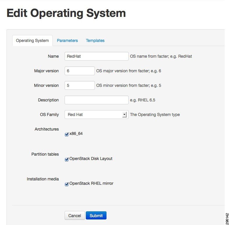
Step 2![]() Check the check-boxes next to the parameters Architectures, Partition Tables and Installation media (Figure 4-70).
Check the check-boxes next to the parameters Architectures, Partition Tables and Installation media (Figure 4-70).
Figure 4-70 Editing the Operating System Parameters and Settings
Configure Provisioning Template
Perform the following procedure to configure the Provisioning template.
Step 1![]() Navigate to the Provisioning template to associate the provisioning template with the correct operating system (Figure 4-71).
Navigate to the Provisioning template to associate the provisioning template with the correct operating system (Figure 4-71).
Figure 4-71 Navigating to the Provisioning Template Settings

Step 2![]() Edit the OpenStack Kickstart template and OpenStack the PXE template. Under the Association Tab, check the check-box next to the Red Hat 6.5 (Figure 4-72).
Edit the OpenStack Kickstart template and OpenStack the PXE template. Under the Association Tab, check the check-box next to the Red Hat 6.5 (Figure 4-72).
Figure 4-72 Editing Template for Provisioning

Configuring Host Groups
Perform the following procedure to configure host groups.
Step 1![]() To override any default values/add values in any of the configuration files we edit the host group values for a existing host group (Figure 4-73). Click More, and then click Host Groups under the Configuration menu.
To override any default values/add values in any of the configuration files we edit the host group values for a existing host group (Figure 4-73). Click More, and then click Host Groups under the Configuration menu.
Figure 4-73 Navigating to the Host Group Settings

Figure 4-74 shows the default host groups in the Host groups section Foreman UI.
Figure 4-74 Default Host Group Listing

Step 2![]() The current deployment configuration uses a controller node that uses Neutron, a Neutron based Network node and a Compute Node that uses Neutron. Therefore, edit three (Compute Neutron, Controller Neutron, Neutron Networker) default templates to override some of the default values in the configuration files.
The current deployment configuration uses a controller node that uses Neutron, a Neutron based Network node and a Compute Node that uses Neutron. Therefore, edit three (Compute Neutron, Controller Neutron, Neutron Networker) default templates to override some of the default values in the configuration files.
Controller Host Group Configuration
Perform the following procedure to configure the controller host group.
Step 1![]() Click open controller (neutron) and go to the Parameters tab.
Click open controller (neutron) and go to the Parameters tab.
Step 2![]() Click override button on each of these parameters listed in Table 4-2 and provide appropriate values for the them.
Click override button on each of these parameters listed in Table 4-2 and provide appropriate values for the them.
The parameters for the Cisco Nexus Plug-in tells Neutron how to log in to the ToR switches, and map the physical hosts to interfaces on the Top of Rack. Since the Cisco UCS Fabric Interconnect sits between the server and the ToR switches, the same interfaces are configured for all servers.
Sample config after completion should resemble values in Figure 4-75.
Figure 4-75 Example Configuration for Controller Host Group

Compute Host Group Configuration
Perform the following procedure to configure the compute host group.
Step 1![]() Click open compute (neutron) and go to the Parameters tab.
Click open compute (neutron) and go to the Parameters tab.
Step 2![]() Click override button on each of these parameters listed in Table 4-3 and provide appropriate values for them.
Click override button on each of these parameters listed in Table 4-3 and provide appropriate values for them.
|
|
|
|---|---|
In this section you can override any other configuration parameter, like passwords.
After the configuration is done the overridden values should resemble values in Figure 4-76
Figure 4-76 Example Configuration for Compute Host Group

Networker Node Host Group Configuration
Perform the following procedure to configure the network Networker node host group.
Step 1![]() Click open Neutron Networker and go to the Parameters tab.
Click open Neutron Networker and go to the Parameters tab.
Step 2![]() Click the override button on each of these parameters listed in Table 4-4 and provide appropriate values for them.
Click the override button on each of these parameters listed in Table 4-4 and provide appropriate values for them.
|
|
|
|---|---|
After the configuration is done the overridden parameters should resemble values in Figure 4-77.
Figure 4-77 Example Configuration for Neutron Networker Host Group

Installation of Controller and Compute and Network Nodes
Installation of computes and controllers nodes can happen in two modes:
1.![]() Where the installation of base operating system happens over the PXE.
Where the installation of base operating system happens over the PXE.
2.![]() You can have the basic install of operating system manually and then add it to the build node.
You can have the basic install of operating system manually and then add it to the build node.
Installing Nodes via PXE (Provisioning Method)
Perform the following procedure to install nodes via PXE (provisioning method).
Step 1![]() Navigate to the add Host section through the top-level hosts tab on the page.
Navigate to the add Host section through the top-level hosts tab on the page.
Installation of Compute, Controller and Network involves common steps.
Step 2![]() While adding different type of nodes, select the appropriate value under the host group drop down menu. Ex. If you are adding a controller, select Controller (neutron) from the drop down menu of the host group, similarly for compute and network node appropriate values need to be selected.
While adding different type of nodes, select the appropriate value under the host group drop down menu. Ex. If you are adding a controller, select Controller (neutron) from the drop down menu of the host group, similarly for compute and network node appropriate values need to be selected.
Step 3![]() Fill the details on the Name, Network, and Operating System Info from the drop down menus (Figure 4-78). You can use the default values from the drop-down menu until it is specified here to use a custom value (Values like IPs would be filled according to your network settings).
Fill the details on the Name, Network, and Operating System Info from the drop down menus (Figure 4-78). You can use the default values from the drop-down menu until it is specified here to use a custom value (Values like IPs would be filled according to your network settings).
Step 4![]() Under the Network tab, provide the MAC address of the to-be compute, controller and network nodes that are required to installed via PXE boot.
Under the Network tab, provide the MAC address of the to-be compute, controller and network nodes that are required to installed via PXE boot.
Step 5![]() Under the Operating System tab, you can set the root password for the Operating system and also verify if the provisioning templates are configured properly, by clicking on the Resolve button. For configuring the provisioning templates refer to Configure Provisioning Template.
Under the Operating System tab, you can set the root password for the Operating system and also verify if the provisioning templates are configured properly, by clicking on the Resolve button. For configuring the provisioning templates refer to Configure Provisioning Template.
The Add interface on the foreman UI is non-functional. Hence we need to add interface either manually after the Node is provisioned else add it to the PXE template to automate it.
- Manual Solution—After the nodes are installed, manually go to each compute Node and Networker node and manually configure the "eth2" by editing the "/etc/sysconfig/network-scripts/ifcfg-eth2" and bring it up command "ifconfig eth2 up".
- Automated Solution—Edit the Openstack PXE template under the Provision Templates section in Foreman to add the following line in the kickstart file defined there.
Figure 4-78 Add New Host Page in Foreman UI

Step 6![]() After completely adding the details under all the above tabs, click Submit. Now, reboot the machines on which compute, controller and network nodes have to me installed. Make sure that the PXE is enabled in the boot settings and the NIC card is set at PXE enabled. While the machines are getting powered on, ensure PXE boot as the boot method and let it boot up and Operating system to be installed via PXE and later let puppet configure the OpenStack on them. Once the systems are completely installed, you can access horizon (OpenStack Web-UI) by entering IP/hostname of the control node in your browser as the URL.
After completely adding the details under all the above tabs, click Submit. Now, reboot the machines on which compute, controller and network nodes have to me installed. Make sure that the PXE is enabled in the boot settings and the NIC card is set at PXE enabled. While the machines are getting powered on, ensure PXE boot as the boot method and let it boot up and Operating system to be installed via PXE and later let puppet configure the OpenStack on them. Once the systems are completely installed, you can access horizon (OpenStack Web-UI) by entering IP/hostname of the control node in your browser as the URL.
Adding Nodes Manually (Non-Provisioning Method)
Perform the following procedure to add nodes manually (non-provisioning method).
Step 1![]() Add hosts (controller/compute/network) to the build node as specified in the “Installing Nodes via PXE (Provisioning Method)” section.
Add hosts (controller/compute/network) to the build node as specified in the “Installing Nodes via PXE (Provisioning Method)” section.
Step 2![]() Install Red Hat Enterprise Linux 6.5 Operating System on servers and register them. (same steps as mentioned earlier for the registration of the build node can be used).
Install Red Hat Enterprise Linux 6.5 Operating System on servers and register them. (same steps as mentioned earlier for the registration of the build node can be used).
Step 3![]() Copy the foreman_client.sh file from /tmp folder on the build node to each of your manually installed nodes.
Copy the foreman_client.sh file from /tmp folder on the build node to each of your manually installed nodes.
Step 4![]() Run foreman_client.sh on each of the nodes (compute/controller/network). The script will configure each of the nodes as configured in Foreman.
Run foreman_client.sh on each of the nodes (compute/controller/network). The script will configure each of the nodes as configured in Foreman.
Workaround for Known Bugs after Installing Nodes
On the network node there is a workaround for known issues.
The following is a workaround for Bug Red Hat Bugzilla 1080646.
Workaround for Isolating Metadata
On the network node there is a workaround for isolating metadata.
Workaround for Correcting the Neutron init-script for the Cisco Neutron Plugin
On the controller node there is a workaround for correcting the neutron init-script for the Cisco Neutron plugin to work properly.
Ink Tank Ceph Installation
The following sections define the details of configuring Ceph Storage.
2.![]() Configuring Ink Tank Repositories
Configuring Ink Tank Repositories
5.![]() Creating a Ceph Storage Cluster
Creating a Ceph Storage Cluster
6.![]() Configuring OpenStack to use Ceph
Configuring OpenStack to use Ceph
Pre-Requisite
An Ink Tank subscription [http://www.inktank.com] is necessary to get the supported packages from their repository. The following is required:
Configuring Ink Tank Repositories
Perform the following procedure to configure Ink Tank repositories.
Step 1![]() Create a file /etc/yum.repos.d/inktank.repo with the contents below [replace the username/password at the appropriate places.
Create a file /etc/yum.repos.d/inktank.repo with the contents below [replace the username/password at the appropriate places.
Note The ink tank repo needs to be added on all the computer and controller nodes apart from adding it to the ceph nodes.
Step 2![]() Once the repository is configured, run update on the repositories using the yum update command.
Once the repository is configured, run update on the repositories using the yum update command.
Installing Ceph Deploy
Perform the following procedure for installing Ceph Deploy.
Ceph-deploy is a utility that would help in setting up the rest of the ceph cluster (mon-OSD nodes).
Step 1![]() Run the yum install -y ceph-deploy command.
Run the yum install -y ceph-deploy command.
Step 2![]() Run the ceph-deploy --version command to validate.
Run the ceph-deploy --version command to validate.
The version should show 1.5.1.
Setting up Ceph Nodes
Perform the following procedure to set up Ceph nodes.
Step 1![]() On each node, set up a password-less SSH access for the user ceph.
On each node, set up a password-less SSH access for the user ceph.
Step 2![]() Stop the iptables service and make sure the time on each machine is in sync.
Stop the iptables service and make sure the time on each machine is in sync.
Step 3![]() Create a user on each node.
Create a user on each node.
Step 4![]() Add root privileges for the user on each Ceph Node.
Add root privileges for the user on each Ceph Node.
Step 5![]() Install an SSH server (if necessary) on each Ceph Node.
Install an SSH server (if necessary) on each Ceph Node.
Step 6![]() Configure your ceph-deploy admin node with password-less SSH access to each Ceph Node. When configuring SSH access, do not use sudo or the root user. Leave the passphrase empty.
Configure your ceph-deploy admin node with password-less SSH access to each Ceph Node. When configuring SSH access, do not use sudo or the root user. Leave the passphrase empty.
Step 7![]() Copy the key to each Ceph Node.
Copy the key to each Ceph Node.
Step 8![]() Modify the ~/.ssh/config file of your ceph-deploy admin node so that it logs in to Ceph Nodes as the user you created (e.g., ceph).
Modify the ~/.ssh/config file of your ceph-deploy admin node so that it logs in to Ceph Nodes as the user you created (e.g., ceph).
Creating a Ceph Storage Cluster
Perform the following procedure to create a Ceph storage cluster.
Step 1![]() Create the cluster, [ceph-deploy new {initial-monitor-node(s)}].
Create the cluster, [ceph-deploy new {initial-monitor-node(s)}].
Step 2![]() If you have more than one network interface, add the public network setting under the [global] section of your Ceph configuration file. See the Network Configuration Reference for details [network = {ip-address}/{netmask}].
If you have more than one network interface, add the public network setting under the [global] section of your Ceph configuration file. See the Network Configuration Reference for details [network = {ip-address}/{netmask}].
Step 3![]() Edit ~/.cephdeploy.conf to add the following at the end of the file.
Edit ~/.cephdeploy.conf to add the following at the end of the file.
Step 4![]() Install Ceph on the monitor and storage nodes, [ceph-deploy install -release 1.1 node1 node2 node3].
Install Ceph on the monitor and storage nodes, [ceph-deploy install -release 1.1 node1 node2 node3].
Step 5![]() Add the initial monitor(s) and gather the keys, [ceph-deploy mon create-initial].
Add the initial monitor(s) and gather the keys, [ceph-deploy mon create-initial].
Ex: ceph-deploy mon create-initial
Once you complete the process, your local directory should have the following keyrings:
Step 6![]() Use ceph-deploy to copy the configuration file and admin key to your admin node and your Ceph Nodes so that you can use the ceph CLI without having to specify the monitor address and ceph.client.admin.keyring each time you execute a command, [ceph-deploy admin {ceph-node}].
Use ceph-deploy to copy the configuration file and admin key to your admin node and your Ceph Nodes so that you can use the ceph CLI without having to specify the monitor address and ceph.client.admin.keyring each time you execute a command, [ceph-deploy admin {ceph-node}].
Ex: ceph-deploy admin node1 node2 node3 admin-node
Note Since you are using ceph-deploy to talk to the local host (admin-node), your host must be reachable by its hostname (e.g., you can modify /etc/hosts if necessary).
Step 7![]() Ensure that you have the correct permissions for the ceph.client.admin.keyring, [sudo chmod +r /etc/ceph/ceph.client.admin.keyring].
Ensure that you have the correct permissions for the ceph.client.admin.keyring, [sudo chmod +r /etc/ceph/ceph.client.admin.keyring].
Step 8![]() Check your cluster's health, [ceph health].
Check your cluster's health, [ceph health].
The cluster should return an active + clean state when it has finished peering.
Step 9![]() Edit /etc/ceph/ceph.conf.
Edit /etc/ceph/ceph.conf.
Preparing the Ceph OSD Nodes
Execute the following commands to prepare and activate Ceph OSD nodes.
Create OSD Pools
Use the following commands to add a Cinder pool and Glance pool to the existing default Ceph pool.
Configuring OpenStack to use Ceph
Perform the following procedure for configuring OpenStack to use Ceph.
Note![]() The FSID of ceph can be obtained from /etc/ceph/ceph.conf. The FSID of ceph can be obtained from /etc/ceph/ceph.conf.
The FSID of ceph can be obtained from /etc/ceph/ceph.conf. The FSID of ceph can be obtained from /etc/ceph/ceph.conf.
Step 1![]() Before configuring block storage on each of the nodes, do the following:
Before configuring block storage on each of the nodes, do the following:
a.![]() Copy ceph.conf and ceph.client.admin.keyring from the primary mon to each compute node's /etc/ceph directory.
Copy ceph.conf and ceph.client.admin.keyring from the primary mon to each compute node's /etc/ceph directory.
a.![]() Copy ceph.conf and ceph.client.admin.keyring from the primary mon to each compute node's /etc/ceph directory.
Copy ceph.conf and ceph.client.admin.keyring from the primary mon to each compute node's /etc/ceph directory.
c.![]() Edit /etc/nova/nova.conf and set the following params:
Edit /etc/nova/nova.conf and set the following params:
a.![]() Edit /etc/glance/glance-api.conf and set:
Edit /etc/glance/glance-api.conf and set:
b.![]() Restart all Glance services.
Restart all Glance services.
c.![]() Edit /etc/cinder/cinder.conf and set:
Edit /etc/cinder/cinder.conf and set:
d.![]() Restart all Cinder services.
Restart all Cinder services.
a.![]() Create the virsh secret file /root/secret.xml:
Create the virsh secret file /root/secret.xml:
c.![]() Set the virsh secret's value:
Set the virsh secret's value:
d.![]() Edit /etc/nova/nova.conf and set the following params:
Edit /etc/nova/nova.conf and set the following params:
Known Issues with Ceph
There is a known issue with Ceph.
1.![]() Nova fails to start when nova-metadata-api service running.
Nova fails to start when nova-metadata-api service running.
The error is actually a scheduling issue. The libvirt_rbd opts in nova.conf breaks things. Might be a bug, there were couldn't find rbd path type issues in the scheduler logs. Workaround is to comment them out for now.
 Feedback