Architectural Overview
This document focuses on the architecture for Red Hat Enterprise Linux OpenStack Platform 4.0 on the UCS using Cisco UCS C-series servers for storage. Cisco UCS C220 M3 servers are used as compute nodes and UCS C240 M3 servers are used as storage nodes. Storage high availability and redundancy are achieved using Ceph storage services on OpenStack. UCS C-series servers are managed by UCSM, which provides ease of infrastructure management and built-in network high availability.
Table 3-1 lists the various hardware and software components, which occupies different tiers of the architecture under test:
|
|
|
|
|
|---|---|---|---|
Table 3-2 lists the C220M3 server configuration used as storage nodes in this architecture (per server basis).
|
|
|
|---|---|
2 x Intel® Xenon ® E5-2650 V2, CPUs 2.6 GHz, 8cores, 16 threads |
|
Cisco UCS RAID SAS 2008M-8i Mezzanine Card, With 6 x 300 GB disks for RAID6 configuration |
Table 3-3 lists the C240M3 server configuration used as storage nodes in this architecture (per server basis).
|
|
|
|---|---|
2 x Intel® Xenon ® E5-2650 V2, CPUs 2.6 GHz, 8cores, 16 threads |
|
Cisco UCS RAID SAS 2008M-8i, With 12 x 900 GB disks, with RAID1 and RAID0 configuration |
Figure 3-1 highlights the high level design points of RHEL OpenStack Platform architecture on Cisco UCS Platform:
- Redundant UCS FIs, Fabric Extenders and multiple cables provide network high availability
- Multiple hard disks per storage node combined with multiple storage nodes provide storage high availability through OpenStack Ceph module
- Management and production network are combined within the UCS Fabric. On the 6200, the management VLAN is bifurcated to a separate 1GE network using the disjoint VLAN feature. Out of band UCS management and other legacy infrastructure components are connected to via this network.
Figure 3-1 Reference Architecture
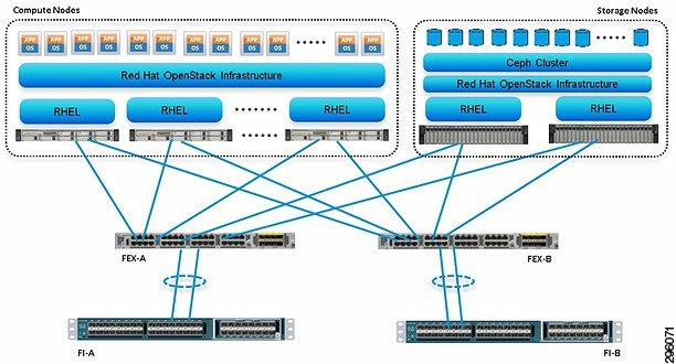
This design does not dictate or require any specific layout of infrastructure network. The Out Of Band UCS Manager access, hosting of supporting infrastructure such as Syslog server can be hosted on infrastructure network. However, design does require accessibility of certain VLANs from the infrastructure network to reach the servers.
This section details the following architectural considerations.
Virtual Networking
This architecture demonstrates use and benefits of Adapter-FEX technology using Cisco UCS VIC adapter. Each C220 M3 and C240 M3 server has one Cisco VIC 1225 physical adapter with two 10 GE links going to fabric A and fabric B for high availability. Cisco UCS VIC 1225 presents three virtual Network Interface Cards (vNICs) to the hypervisor with three virtual interfaces (on each fabric) in active/passive mode. These vNICs are capable to do fabric failover, so if the Fabric Extender of Fabric Interconnect reboots or all the uplinks on the FI are lost, the vNIC would move traffic from fabric A to fabric B (or vice-a-versa) transparently. The MAC addresses to these vNICs are assigned using MAC address pool defined on the UCSM.
In the hypervisor layer, this architecture is using Neutron networking layer, with Nexus and Open-vSwitch for virtual networking. Different VLANs are used for different tenants for logical separation of domains. Within a given tenant’s realm, different VLANs can be used on per tier basis too in case of multi-tier applications. In other words, architecture does not dictate one VLAN per tenant.
Storage Virtualization
There are 12 x 900 GB SAS disks per C240 M3 server. First two disks are put in RAID 1 configuration and is the bootable device. Red Hat Enterprise Linux 6.5 is installed on this RAID 1 volume. All remaining 10 disks are configured as individual disks in RAID0 configuration. In Linux terminology, /dev/sda is where OS is installed and the disks /dev/sdb to /dev/sdk are available to Ceph as storage devices.
The Ceph Storage Cluster is the foundation for all Ceph deployments. Based upon RADOS, Ceph Storage Clusters consist of two types of daemons: a Ceph OSD Daemon (OSD) stores data as objects on a storage node; and a Ceph Monitor maintains a master copy of the cluster map. A Ceph Storage Cluster may contain thousands of storage nodes. A minimal system will have at least one Ceph Monitor and three Ceph OSD Daemons for data replication.
The Ceph File System, Ceph Object Storage and Ceph Block Devices read data from and write data to the Ceph Storage Cluster. The Ceph File System (Ceph FS) is a POSIX-compliant file system that uses a Ceph Storage Cluster to store its data. The Ceph file system uses the same Ceph Storage Cluster system as Ceph Block Devices, Ceph Object Storage with its S3 and Swift APIs, or native bindings (librados). Block-based storage interfaces are the most common way to store data with rotating media such as hard disks, CDs, floppy disks, and even traditional 9-track tape. The ubiquity of block device interfaces makes a virtual block device an ideal candidate to interact with a mass data storage system like Ceph.
Ceph block devices are thin-provisioned, re-sizable and store data striped over multiple OSDs in a Ceph cluster. Ceph block devices leverage RADOS capabilities such as snapshotting, replication and consistency. Ceph’s RADOS Block Devices (RBD) interact with OSDs using kernel modules or the librbd library. Ceph’s block devices deliver high performance with infinite scalability to kernel modules, or to KVMs such as Qemu, and cloud-based computing systems like OpenStack and CloudStack that rely on libvirt and Qemu to integrate with Ceph block devices. You can use the same cluster to operate the Ceph RADOS Gateway, the Ceph FS file system, and Ceph block devices simultaneously.
Service Profile Design
This architecture implements following design steps to truly achieve stateless computing on the servers:
- Service profiles are derived from service profile template for consistency.
- The Red Hat Enterprise Linux host uses following identities in this architecture:
–![]() Mac Addresses: one per each vNIC on the server
Mac Addresses: one per each vNIC on the server
- All of these identifiers are defined in their respective identifier pools and the pool names are referred in the service profile template.
- Server pools are defined with automatic qualification policy and criteria. Rack servers are automatically put in the pool as and when they are fully discovered by UCS Manager. This eliminates the need to manually assign servers to server pool.
- Service profile template is associated to the server pool. This eliminates the need to individually associating service profiles to physical servers.
Given this design and capabilities of UCS and UCS Manager, a new server can be procured within minutes if the scale needs to be increased or if a server needs to be replaced by different hardware. In case, if a server has physical fault (faulty memory, or PSU or fan, for example), using following steps, a new server can be procured within minutes:
- Put the faulty server in maintenance mode. This would move VMs running on fault server to other healthy servers on the cluster.
- Disassociate the service profile from the faulty server and physically remove the server for replacement of faulty hardware (or to completely remove the faulty server).
- Physically install the new server and connect it to the Fabric Extenders. Let the new server be discovered by UCS Manager.
- Associate the service profile to the newly deployed rack server and install Red Hat Enterprise Linux on the local disk.
- The new server would assume the role of the old server with all the identifiers intact.
Given that this architecture assumes deployment of OpenStack from scratch, there is no external image repository available. Once, storage nodes are up and running, you can even host the images. Thus, the architecture achieves the true statelessness of the computing in the data-center. If there are enough identifiers in all the id-pools, and if more servers are attached to UCS system in future, more service profiles can be derived from the service profile template and the private cloud infrastructure can be easily expanded.
Network High Availability Design
Following are the key aspects of this solution:
- Cisco adapter-FEX technology to introduce virtual NICs to host OS
- Fabric failover feature of adapter-FEX is exploited to provide high availability
- Two 10GE links between FI and FEX provides enough bandwidth over subscription for the given size of cloud. The over subscription can be reduced by adding more 10GE links between FI and FEX if needed by the VMs running on the hosts.
- Three vNICs per host—one for private network within the OpenStack environment and one for the public access of the Linux hosts.
- All the VLANS are divided in two groups—one having their active data network on fabric A and one having their active data network on fabric B. This achieves fair load balancing on two fabrics in addition to the redundancy.

Note![]() Due to neutron bug 1288393, high availability in the ToR layer was removed. Once this bug is resolved, however, redundant links can be re-enabled to make the ToR layer highly available. Due to neutron bug 1288393, high availability in the ToR layer was removed. Once this bug is resolved, however, redundant links can be re-enabled to make the ToR layer highly available.
Due to neutron bug 1288393, high availability in the ToR layer was removed. Once this bug is resolved, however, redundant links can be re-enabled to make the ToR layer highly available. Due to neutron bug 1288393, high availability in the ToR layer was removed. Once this bug is resolved, however, redundant links can be re-enabled to make the ToR layer highly available.
OpenStack Services Placement
Table 3-4 shows the final service placement for all OpenStack services. The API-listener services (including neutron-server) run on the cloud controller to field client requests. The Network node runs all other Network services except for those necessary for Nova client operations, which also run on the Compute nodes. The Dashboard runs on the client system to prevent self-service users from accessing the cloud controller directly.
|
|
|
|
|---|---|---|
openstack-nova-scheduler, *-glance-api, *-keystone |
||
Sizing Guidelines
In any discussion about virtual infrastructures, it is important to first define a reference workload. Not all servers perform the same tasks, and it is impractical to build a reference that takes into account every possible combination of workload characteristics.
Defining the Reference Workload
To simplify the discussion, we have defined a representative customer reference workload. By comparing your actual customer usage to this reference workload, you can extrapolate which reference architecture to choose.
OpenStack defines various reference VMs as shown in Table 3-5 .
|
|
|
|---|---|
This specification for a virtual machine is not intended to represent any specific application. Rather, it represents a single common point of reference to measure other virtual machines.
You must design your cloud to provide N + 1 hosts high availability. To do so, consider the largest resource required by all the VMs, divide it by the single physical server resources and round it up. This would give you required number of hosts. Add one more host to provide N+1 HA.
For example, all the instances required to run on your cloud would require combined 620 GB of RAM. With 128 GB RAM per server, this would require 5 servers. To provide N + 1 HA, you would need 6 compute nodes and divide the load across all the hosts. In this case, if one of the hosts has to go down for maintenance, remaining servers can still carry the load of all instances. This example assumes that RAM requirements is the highest across all instances.
 Feedback