Overview

Overview

You can deploy the Tetration (Secure Workload) M5 cluster in either of the following ways:

  • Large-form factor 39-rack unit (RU) platform (C1-Tetration single rack) for data centers with more than 5000 servers


    Note

    You can deploy the large-form factor platform in either one or two racks depending on your requirements. See the following C1-Tetration single rack and dual rack figures for examples.
  • Small-form factor 8-RU platform (C1-Tetration-M) for data centers with fewer than 5000 servers. See the C1-Tetration-M figure for the example.

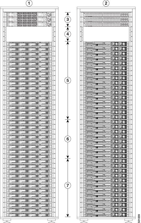
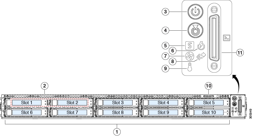
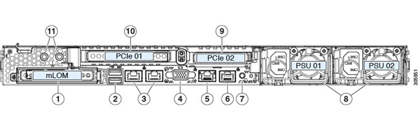
The following figure shows the front and rear of the C1-Tetration single rack.

Figure 1. C1-Tetration Single Rack Front and Rear

1

Front (cold aisle view)

2

Rear (hot aisle view)

3

One spine (RU 42) and two leaf switches: leaf 2 (RU 40) and leaf 1 (RU 41)

4

Open rack units (RU 37 to 39)

5

16 compute servers (RU 21 to 36)

6

Eight serving servers (RU 13 to 20)

7

12 base servers (RU 1 to 12)

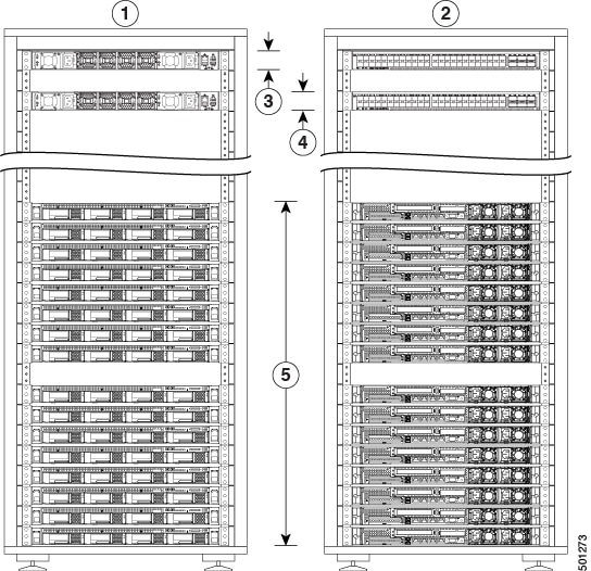
The following figure shows the front and rear of rack one of the C1-Tetration dual rack.

Figure 2. C1-Tetration Dual Rack—Rack 1 Front and Rear

1

Front (cold aisle view)

2

Rear (hot aisle view)

3

One spine switch (RU 42)

4

Leaf 1 switch (RU 40)

5

16 compute servers (RU 1 to 4 and 6 to 9)

6

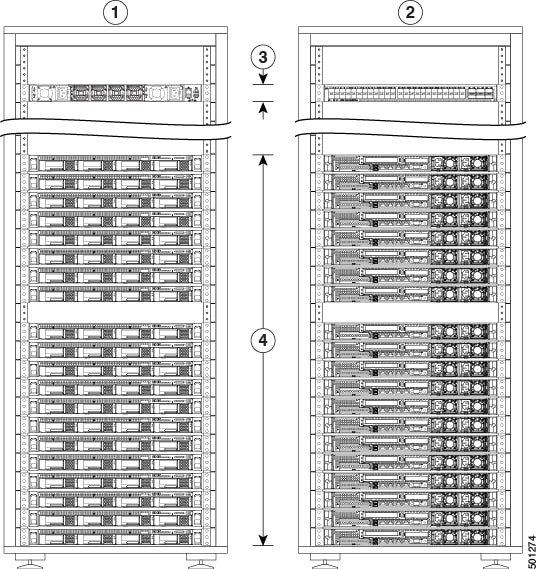
The following figure shows the front and rear of rack 2 of the C1-Tetration dual rack.

Figure 3. C1-Tetration Dual Rack— Rack 2 Front and Rear

1

Front (cold aisle view)

2

Rear (hot aisle view)

3

Leaf 2 switch (RU 40)

4

Eight serving servers (RU 14 to 21) and 12 base servers (RU 1 to 12)

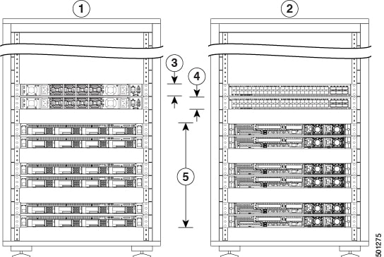
The following figure shows the front and rear of the C1-Tetration-M.

Figure 4. C1-Tetration-M Front and Rear

1

Front (cold aisle view)

2

Rear (hot aisle view)

3

Leaf 1 switch (RU 12)

4

Leaf 2 switch (RU 11)

5

Six universal servers (RU 2, 3, 5, 6, 8, and 9)

Cisco UCS C220 M5 Server (SFF Drives) Front Panel

The following figure shows the front panel of the UCS C220 M5 server with small form-factor (SFF) drives.

See Cisco UCS C220 M5 Server Installation and Service Guide for more information.

Figure 5. Cisco UCS C220 M5 Server (SFF Drives) Front Panel

1

Drive bays 1 to 10

Support for SAS/SATA HDDs and SSDs

2

  • Drive bays 1 and 2 support NVMe PCIe SSDs (model UCSC-220-M5SX).

  • Drive bays 1 to 10 support only NVMe PCIe SSDs (model UCSC-220-M5SN).

3

Power button/power status LED

4

Unit identification button/LED

5

System status LED

6

Power supply status LED

7

Fan status LED

8

Network link activity LED

9

Temperature status LED

10

Pullout asset card

11

KVM connector

Used with a KVM cable that provides one DB-15 VGA, one DB-9 serial, and two USB connectors.

Cisco UCS C220 M5 Server Rear Panel

The following figure shows the rear panel of the UCS C220 M5 Server.

See Cisco UCS C220 M5 Server Installation and Service Guide for more information.

Figure 6. Cisco UCS C220 M5 Server Rear Panel

1

Modular LAN-on-motherboard (mLOM) card bay (x16 PCIe lane)

2

Two USB 3.0 ports

3

Dual 1-Gb/10-Gb Ethernet ports (referred to as LAN1 and LAN2, or LOM port 1 and LOM port 2)

The dual LAN ports can support 1 Gbps and 10 Gbps depending on the link partner capability.

4

VGA video port (DB-15 connector)

5

1-Gb Ethernet dedicated management port

6

Serial port (RJ-45 connector)

7

Rear unit identification button/LED

8

Two power supplies (redundant as 1+1)

9

PCIe riser 2/slot 2 (x16 lane)

Includes PCIe cable connectors for front-loading NVMe SSDs (x8 lane)

10

PCIe riser 1/slot 1 (x16 lane)

11

Threaded holes for dual-hole grounding lug