Device Settings

After you add a device, you can edit device-related settings on the Device page.

  1. Choose Devices > Device Management.

  2. Next to the device you want to modify, click Edit (edit icon).

  3. Click Device.

Edit General Settings

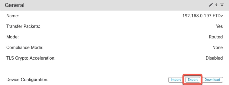
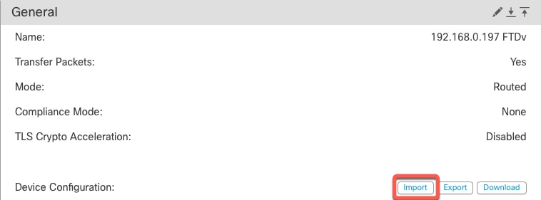
The General section of the Device page displays the settings described in the table below.

Table 1. General Section Table Fields

Field

Description

Name

The display name of the device on the FMC.

Transfer Packets

This displays whether or not the managed device sends packet data with the events to the FMC.

Mode

The displays the mode of the management interface for the device: routed or transparent.

Compliance Mode

This displays the security certifications compliance for a device. Valid values are CC, UCAPL and None.

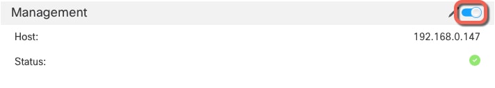
TLS Crypto Acceleration:

Shows whether TLS crypto acceleration is enabled or disabled.

Device Configuration

Lets you copy, export, or import a configuration. See Copy a Configuration to Another Device and Export and Import the Device Configuration.

You can edit some of these settings from this section.

Procedure


Step 1

Choose Devices > Device Management

Step 2

Next to the device you want to modify, click Edit (edit icon).

Step 3

Click Device

Step 4

In the General section, click Edit (edit icon)

  1. Enter a Name for the managed device. 

  2. Check Transfer Packets to allow packet data to be stored with events on the FMC.

  3. Click Force Deploy to force deployment of current policies and device configuration to the device. 

    Note


    Force-deploy consumes more time than the regular deployment since it involves the complete generation of the policy rules to be deployed on the FTD.

Step 5

For Device Configuration actions, see Copy a Configuration to Another Device and Export and Import the Device Configuration.

Step 6

Click Deploy


What to do next

Copy a Configuration to Another Device

When a new device is deployed in the network you can easily copy configurations and policies from a pre-configured device, instead of manually reconfiguring the new device.

Before you begin

Confirm that:

  • The source and destination FTD devices are the same model and are running the same version of the software.

  • The source is either a standalone Firepower Threat Defense device or a Firepower Threat Defense high availability pair.

  • The destination device is a standalone FTD device.

  • The source and destination FTD devices have the same number of physical interfaces.

  • The source and destination FTD devices are in the same firewall mode - routed or transparent.

  • The source and destination FTD devices are in the same security certifications compliance mode.

  • The source and destination FTD devices are in the same domain.

  • Configuration deployment is not in progress on either the source or the destination FTD devices.

Procedure


Step 1

Choose Devices > Device Management.

Step 2

Next to the device you want to modify, click Edit (edit icon).

Step 3

Click Device.

Step 4

In the General section, do one of the following:

  • Click Get Device Configuration (get device configuration icon) to copy device configuration from another device to the new device. On the Get Device Configuration page, select the source device in the Select Device drop-down list.
  • Click Push Device Configuration (push device configuration icon) to copy device configuration from the current device to the new device. On the Push Device Configuration page, select the destination to which configuration is to be copied in the Target Device drop-down list.

Step 5

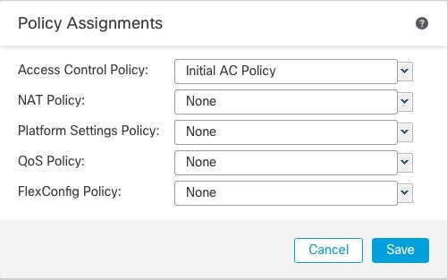
(Optional) Check Include shared policies configuration check box to copy policies.

Shared policies like AC policy, NAT, Platform Settings and FlexConfig policies can be shared across multiple devices.

Step 6

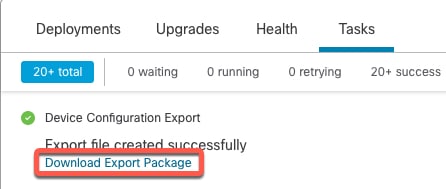
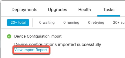
Click OK.

You can monitor the status of the copy device configuration task on Tasks in the Message Center.


When the copy device configuration task is initiated, it erases the configuration on the target device and copies the configuration of the source device to the destination device.

Warning


When you have completed the copy device configuration task, you cannot revert the target device to its original configuration.

Export and Import the Device Configuration

You can export all of the the device-specific configuration configurable on the Device pages, including:

  • Interfaces

  • Inline Sets

  • Routing

  • DHCP

  • VTEP

  • Associated objects

You can then import the saved configuration for the same device in the following use cases:

  • Moving the device to a different FMC—First delete the device from the original FMC, then add the device to the new FMC. Then you can import the saved configuration.

  • Moving the device between domains—When you move a device between domains, some device-specific configuration is not retained because supporting objects (such as interface groups for security zones) do not exist in the new domain. By importing the configuration after the domain move, any necessary objects are created for that domain, and the device configuration is restored.

  • Restore an old configuration—If you deployed changes that negatively impacted the operation of the device, you can import a backup copy of a known working configuration to restore a previous operational state.

  • Reregistering a device—If you delete a device from the FMC, but then want to add it back, you can import the saved configuration.

See the following guidelines:

  • You can only import the configuration to the same device (the UUID must match). You cannot import a configuration to a different device, even if it is the same model.

  • Do not change the version running on the device between exporting and importing; the version must match.

  • When moving the device to a different FMC, the target FMC version must be the same as the source version.

  • If an object doesn't exist, it will be created. If an object exists, but the value is different, see below:

    Table 2. Object Import Action

    Scenario

    Import Action

    Object exists with the same name and value.

    Reuse existing objects.

    Object exists with the same name but different value.

    Network and Port objects: Create object overrides for this device. See Object Overrides.

    Interface objects: Create new objects. For example, if both the type (security zone or interface group) and the interface type (routed or switched, for example) do not match, then a new object is created.

    All other objects: Reuse existing objects even though the values are different.

    Object doesn't exist.

    Create new object.s

Procedure


Step 1

Choose Devices > Device Management.

Step 2

Next to the device you want to edit, click Edit (edit icon).

Step 3

Click Device.

Step 4

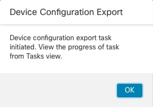
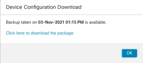
Export the configuration.

  1. In the General area, click Export.

    Figure 1. Export Device Configuration
    Export Device Configuration

    You are prompted to acknowledge the export; click OK.

    Figure 2. Acknowledge Export
    Acknowldge Export

    You can view the export progress in the Tasks page.

  2. On the Notifications > Tasks page, ensure that the export has completed; click Download Export Package. Alternatively, you can click the Download button in the General area.

    Figure 3. Export Task
    Export Task

    You are prompted to download the package; click Click here to download the package to save the file locally, and then click OK to exit the dialog box.

    Figure 4. Download Package
    Download Package

Step 5

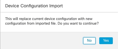
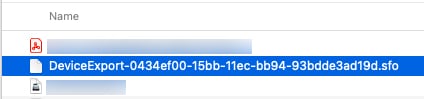
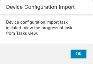
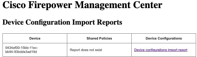
Import the configuration.

  1. In the General area, click Import.

    Figure 5. Import Device Configuration
    Import Device Configuration

    You are prompted to acknowledge that the current configuration will be replace. Click Yes, and then navigate to the configuration package (with the suffix .sfo; note that this file is different from the Backup/Restore files).

    Figure 6. Import Package
    Import Package
    Figure 7. Navigate to Package
    Navigate to Package

    You are prompted to acknowledge the import; click OK.

    Figure 8. Acknowledge Import
    Acknowledge Import

    You can view the import progress in the Tasks page.

  2. View the import reports so you can see what was imported. On the Notifications > Tasks page for the import task, click View Import Report.

    Figure 9. View Import Report
    View Import Report

    The Device Configuration Import Reports page provides links to available reports.


Edit License Settings

The License section of the Device page displays the licenses enabled for the device.

You can enable licenses on your device if you have available licenses on your FMC.

Procedure


Step 1

Choose Devices > Device Management.

Step 2

Next to the device where you want to enable or disable licenses, click Edit (edit icon).

Step 3

Click Device.

Step 4

In the License section, click Edit (edit icon).

Step 5

Check or clear the check box next to the license you want to enable or disable for the managed device.

Step 6

Click Save.


What to do next

View System Information

The System section of the Device page displays a read-only table of system information, as described in the following table.

You can also shut down or restart the device.

Figure 10. System
System
Figure 11. Inventory Details
Inventory Details
Table 3. System Section Table Fields

Field

Description

Shut Down Device (shut down device icon)

Shuts down the device. See Shut Down or Restart the Device.

Restart Device (restart device icon)

Restarts the device. See Shut Down or Restart the Device.

Model

The model name and number for the managed device.

Serial

The serial number of the chassis of the managed device.

Time

The current system time of the device.

Time Zone

Shows the time zone.

Version

The version of the software currently installed on the managed device.

Time Zone setting for time-based rules

The current system time of the device, in the time zone specified in device platform settings.

Inventory

Link to view the device inventory: Fans, Memory, CPU, Power Supply, Storage, and Network Modules.

Edit Health Settings

The Health section of the Device page displays the information described in the table below.

Table 4. Health Section Table Fields

Field

Description

Status

An icon that represents the current health status of the device. Clicking the icon displays the Health Monitor for the appliance.

Policy

A link to a read-only version of the health policy currently deployed at the device.

Excluded

A link to the Health Exclude page, where you can enable and disable health exclusion modules.

Edit Management Settings

You can edit management settings in the Management area.

Update the Hostname or IP Address in the FMC

If you edit the hostname or IP address of a device after you added it to the FMC (using the device’s CLI, for example), you need to use the procedure below to manually update the hostname or IP address on the managing FMC.

To change the device management IP address on the device, see Modify FTD Management Interfaces at the CLI.

If you used only the NAT ID when registering the device, then the IP shows as NO-IP on this page, and you do not need to update the IP address/hostname.

Procedure


Step 1

Choose Devices > Device Management.

Step 2

Next to the device where you want to modify management options, click Edit (edit icon).

Step 3

Click Device, and view the Management area.

Step 4

Disable management temporarily by clicking the slider so it is disabled Slider disabled (slider disabled).

You are prompted to proceed with disabling management; click Yes.

Disabling management blocks the connection between the FMC and the device, but does not delete the device from the FMC.

Step 5

Edit the Host IP address or hostname by clicking Edit (edit icon).

Step 6

In the Management dialog box, modify the name or IP address in the Host field, and click Save.

Figure 12. Management IP Address
Management IP Address

Step 7

Reenable management by clicking the slider so it is enabled Slider enabled (slider enabled).

Figure 13. Enable Management Connection
Enable Management Connection

Change Both Management Center and Threat Defense IP Addresses

You might want to change both FMC and FTD IP addresses if you need to move them to a new network.

Procedure


Step 1

Disable the management connection.

For a high-availability pair or cluster, perform these steps on all units.

  1. Choose Devices > Device Management.

  2. Next to the device, click Edit (edit icon).

  3. Click Device, and view the Management area.

  4. Disable management temporarily by clicking the slider so it is disabled (slider disabled).

    You are prompted to proceed with disabling management; click Yes.

Step 2

Change the device IP address in the FMC to the new device IP address.

You will change the IP address on the device later.

For a high-availability pair or cluster, perform these steps on all units.

  1. Edit the Host IP address or hostname by clicking Edit (edit icon).

  2. In the Management dialog box, modify the name or IP address in the Host field, and click Save.

    Figure 14. Management IP Address
    Management IP Address

Step 3

Change the FMC IP address.

Caution


Be careful when making changes to the FMC interface to which you are connected; if you cannot re-connect because of a configuration error, you need to access the FMC console port to re-configure the network settings in the Linux shell. You must contact Cisco TAC to guide you in this operation.

  1. Choose System (system gear icon) > Configuration, and then choose Management Interfaces.

  2. In the Interfaces area, click Edit next to the interface that you want to configure.

  3. Change the IP address, and click Save.

Step 4

Change the manager IP address on the device.

For a high-availability pair or cluster, perform these steps on all units.

  1. At the FMC CLI, view the unique UUID for the FMC so you can specify it in the FTD command. For information about the FMC CLI, see Firepower Management Center Command Line Reference in the Firepower Management Center Administration Guide.

    show version

    The FMC UUID definitively identifies the FMC; for example, in the case of FMC high availability, you need to specify the active FMC on the FTD.

    Example:

    
    > show version 
    -------------------[ firepower ]--------------------
    Model                     : Cisco Firepower Management Center for VMWare (66) Version 6.7.0 (Build 1222)
    UUID                      : f7ffad78-bf16-11ec-a737-baa2f76ef602
    Rules update version      : 2020-05-26-001-vrt
    VDB version               : 334
    ----------------------------------------------------
  2. Edit the FMC IP address or hostname.

    configure manager edit identifier {ip_address | hostname}

    If the FMC was originally identified by DONTRESOLVE and a NAT ID, you can change the value to a hostname or IP address using this command. You cannot change an IP address or hostname to DONTRESOLVE .

    Example:

    
    > configure manager edit f7ffad78-bf16-11ec-a737-baa2f76ef602 10.10.5.1


Step 5

Change the IP address of the manager access interface at the console port.

For a high-availability pair or cluster, perform these steps on all units.

If you use the dedicated Management interface:

configure network ipv4

configure network ipv6

If you use the dedicated Management interface:

configure network management-data-interface disable

configure network management-data-interface

Step 6

Reenable management by clicking the slider so it is enabled (slider enabled).

For a high-availability pair or cluster, perform these steps on all units.

Figure 15. Enable Management Connection
Enable Management Connection

Step 7

(If using a data interface for manager access) Refresh the data interface settings in the FMC.

For a high-availability pair, perform this step on both units.

  1. Choose Devices > Device Management > Device > Management > FMC Access - Configuration Details, and click Refresh.

  2. Choose Devices > Device Management > Interfaces, and set the IP address to match the new address.

  3. Return to the FMC Access - Configuration Details dialog box, and click Acknowledge to remove the deployment block.

Step 8

Ensure the management connection is reestablished.

In the FMC, check the management connection status on the Devices > Device Management > Device > Management > FMC Access - Configuration Details > Connection Status page.

At the FTD CLI, enter the sftunnel-status-brief command to view the management connection status.

The following status shows a successful connection for a data interface, showing the internal "tap_nlp" interface.

Step 9

(For a high-availability FMC pair) Repeat configuration changes on the secondary FMC.

  1. Change the secondary FMC IP address.

  2. Specify the new peer addresses on both units.

  3. Make the secondary unit the active unit.

  4. Disable the device management connection.

  5. Change the device IP address in the FMC.

  6. Reenable the management connection.


Change the Manager Access Interface from Management to Data

You can manage the FTD from either the dedicated Management interface or from a data interface. If you want to change the manager access interface after you added the device to the FMC, follow these steps to migrate from the Management interface to a data interface. To migrate the other direction, see Change the Manager Access Interface from Data to Management.

Initiating the manager access migration from Management to data causes the FMC to apply a block on deployment to the FTD. To remove the block, enable manager access on the data interface.

See the following steps to enable manager access on a data interface and also configure other required settings.

Procedure


Step 1

Initiate the interface migration.

  1. On the Devices > Device Management page, click Edit (edit icon) for the device.

  2. Go to the Device > Management section, and click the link for FMC Access Interface.

    The FMC Access Interface field shows the current Management interface. When you click the link, choose the new interface type, Data Interface, in the Manage device by drop-down list.

  3. Click OK and then Close.

    You must now complete the remaining steps in this procedure to enable manager access on the data interface. The Management area now shows FMC Access Interface: Data Interface, and FMC Access Details: Configuration.

    Figure 16. FMC Access
    FMC Access

    If you click Configuration, the FMC Access - Configuration Details dialog box opens. The FMC Access Mode shows a Deploy pending state.

Step 2

Enable manager access on a data interface on the Devices > Device Management > Interfaces > Edit Physical Interface > FMC Access page.

Check Enable management access and click OK. By default, all networks are allowed, but you can limit access as long as the FMC address is allowed.

If the manager access interface uses a static IP address, you are reminded to configure routing for it.

Click Save on the Interfaces page. See Configure Routed Mode Interfaces for more information about interface settings. You can enable manager access on one routed data interface. Make sure this interface is fully configured with a name and IP address and that it is enabled.

Step 3

(Optional) If you use DHCP for the interface, enable the web type DDNS method on the Devices > Device Management > DHCP > DDNS page.

See Configure Dynamic DNS. DDNS ensures the FMC can reach the FTD at its Fully-Qualified Domain Name (FQDN) if the FTD's IP address changes.

Step 4

Make sure the FTD can route to the FMC through the data interface; add a static route if necessary on Devices > Device Management > Routing > Static Route.

See Add a Static Route.

Step 5

(Optional) Configure DNS in a Platform Settings policy, and apply it to this device at Devices > Platform Settings > DNS.

See DNS. DNS is required if you use DDNS. You may also use DNS for FQDNs in your security policies.

Step 6

(Optional) Enable SSH for the data interface in a Platform Settings policy, and apply it to this device at Devices > Platform Settings > Secure Shell.

See Secure Shell. SSH is not enabled by default on the data interfaces, so if you want to manage the FTD using SSH, you need to explicitly allow it.

Step 7

Deploy configuration changes; see Deploy Configuration Changes.

You will see a validation error to confirm that you are changing the manager access interface. Check Ignore warnings and deploy again.

The FMC will deploy the configuration changes over the current Management interface. After the deployment, the data interface is now ready for use, but the original management connection to Management is still active.

Step 8

At the FTD CLI (preferably from the console port), set the Management interface to use a static IP address and set the gateway to use the data interfaces.

configure network {ipv4 | ipv6} manual ip_address netmask data-interfaces

  • ip_address netmask —Although you do not plan to use the Management interface, you must set a static IP address, for example, a private address so that you can set the gateway to data-interfaces (see the next bullet). You cannot use DHCP because the default route, which must be data-interfaces, might be overwritten with one received from the DHCP server.

  • data-interfaces —This setting forwards management traffic over the backplane so it can be routed through the manager access data interface.

We recommend that you use the console port instead of an SSH connection because when you change the Management interface network settings, your SSH session will be disconnected.

Step 9

If necessary, re-cable the FTD so it can reach the FMC on the data interface.

Step 10

In the FMC, disable the management connection, update the Host IP address for the FTD in the Devices > Device Management > Device > Management section, and reenable the connection.

See Update the Hostname or IP Address in the FMC. If you used the FTD hostname or just the NAT ID when you added the FTD to the FMC, you do not need to update the value; however, you need to disable and reenable the management connection to restart the connection.

Step 11

Ensure the management connection is reestablished.

In the FMC, check the management connection status on the Devices > Device Management > Device > Management > FMC Access - Configuration Details > Connection Status page.

At the FTD CLI, enter the sftunnel-status-brief command to view the management connection status.

The following status shows a successful connection for a data interface, showing the internal "tap_nlp" interface.

If it takes more than 10 minutes to reestablish the connection, you should troubleshoot the connection. See Troubleshoot Management Connectivity on a Data Interface.


Change the Manager Access Interface from Data to Management

You can manage the FTD from either the dedicated Management interface or from a data interface. If you want to change the manager access interface after you added the device to the FMC, follow these steps to migrate from a data interface to the Management interface. To migrate the other direction, see Change the Manager Access Interface from Management to Data.

Initiating the manager access migration from data to Management causes the FMC to apply a block on deployment to the FTD. You must disable manager access on the data interface to remove the block.

See the following steps to disable manager access on a data interface, and also configure other required settings.

Procedure


Step 1

Initiate the interface migration.

  1. On the Devices > Device Management page, click Edit (edit icon) for the device.

  2. Go to the Device > Management section, and click the link for FMC Access Interface.

    The FMC Access Interface field shows the current management interface as data. When you click the link, choose the new interface type, Management Interface, in the Manage device by drop-down list.

  3. Click Save.

    Click OK and then Close.

    You must now complete the remaining steps in this procedure to enable manager access on the Management interface. The Management area now shows the FMC Access Interface: Management Interface, and FMC Access Details: Configuration.

    Figure 17. FMC Access
    FMC Access

    If you click Configuration, the FMC Access - Configuration Details dialog box opens. The FMC Access Mode shows a Deploy pending state.

    Figure 18. FMC Access Mode
    FMC Access Mode

Step 2

Disable manager access on the data interface on the Devices > Device Management > Interfaces > Edit Physical Interface > FMC Access page.

Uncheck Enable management access and click OK. Click Save on the Interfaces page. This step removes the block on deployment.

Step 3

If you have not already done so, configure DNS settings for the data interface in a Platform Setting policy, and apply it to this device at Devices > Platform Settings > DNS.

See DNS. The FMC deployment that disables manager access on the data interface will remove any local DNS configuration. If that DNS server is used in any security policy, such as an FQDN in an Access Rule, then you must re-apply the DNS configuration using the FMC.

Step 4

Deploy configuration changes; see Deploy Configuration Changes.

The FMC will deploy the configuration changes over the current data interface.

Step 5

If necessary, re-cable the FTD so it can reach the FMC on the Management interface.

Step 6

At the FTD CLI, configure the Management interface IP address and gateway using a static IP address or DHCP.

When you originally configured the data interface for manager access, the Management gateway was set to data-interfaces, which forwarded management traffic over the backplane so it could be routed through the manager access data interface. You now need to set an IP address for the gateway on the management network.

Static IP address:

configure network {ipv4 | ipv6} manual ip_address netmask gateway_ip

DHCP:

configure network{ipv4 | ipv6} dhcp

Step 7

In the FMC, disable the management connection, update the Host IP address for the FTD in the Devices > Device Management > Device > Management section, and reenable the connection.

See Update the Hostname or IP Address in the FMC. If you used the FTD hostname or just the NAT ID when you added the FTD to the FMC, you do not need to update the value; however, you need to disable and reenable the management connection to restart the connection.

Step 8

Ensure the management connection is reestablished.

In the FMC, check the management connection status on the Devices > Device Management > Device > Management > Status field or view notifications in the FMC.

At the FTD CLI, enter the sftunnel-status-brief command to view the management connection status.

If it takes more than 10 minutes to reestablish the connection, you should troubleshoot the connection. See Troubleshoot Management Connectivity on a Data Interface.


View Manager Access Details for Data Interface Management

Model SupportFTD

When you use a data interface for FMC management instead of using the dedicated Management interface, you must be careful about changing the interface and network settings for the device in the FMC so you do not disrupt the connection. You can also change the data interface settings locally on the device, which requires you to reconcile those changes in the FMC manually. The Devices > Device Management > Device > Management > FMC Access - Configuration Details dialog box helps you resolve any discrepancies between the FMC and the FTD local configuration.

Normally, you configure the manager access data interface as part of initial FTD setup before you add the FTD to the FMC. When you add the FTD to the FMC, the FMC discovers and maintains the interface configuration, including the following settings: interface name and IP address, static route to the gateway, DNS servers, and DDNS server. For the DNS server, the configuration is maintained locally if it is discovered during registration, but it is not added to the Platform Settings policy in FMC.

After you add the FTD to the FMC, if you change the data interface settings on the FTD locally using the configure network management-data-interface command, then the FMC detects the configuration changes, and blocks deployment to the FTD. The FMC detects the configuration changes using one of the following methods:

  • Deploy to the FTD. Before the FMC deploys, it will detect the configuration differences and stop the deployment.

  • The Sync button in the Interfaces page.

  • The Refresh button on the FMC Access - Configuration Details dialog box.

To remove the block, you must go to the FMC Access - Configuration Details dialog box and click Acknowledge. The next time you deploy, the FMC configuration will overwrite any remaining conflicting settings on the FTD. It is your responsibility to manually fix the configuration in the FMC before you re-deploy.

See the following pages on this dialog box.

Configuration

View the configuration comparison of the manager access data interface on the FMC and the FTD.

The following example shows the configuration details of the FTD where the configure network management-data-interface command was entered on the FTD. The pink highlights show that if you Acknowledge the differences but do not match the configuration in the FMC, then the FTD configuration will be removed. The blue highlights show configurations that will be modified on the FTD. The green highlights show configurations that will be added to the FTD.

The following example shows this page after configuring the interface in the FMC; the interface settings match, and the pink highlight was removed.

CLI Output

View the CLI configuration of the manager access data interface, which is useful if you are familiar with the underlying CLI.

Connection Status

View management connection status. The following example shows that the management connection is still using the Management "br1" interface.

The following status shows a successful connection for a data interface, showing the internal "tap_nlp" interface.

See the following sample output for a connection that is down; there is no peer channel "connected to" information, nor heartbeat information shown:


> sftunnel-status-brief
PEER:10.10.17.202
Registration: Completed.
Connection to peer '10.10.17.202' Attempted at Mon Jun 15 09:21:57 2020 UTC
Last disconnect time : Mon Jun 15 09:19:09 2020 UTC
Last disconnect reason : Both control and event channel connections with peer went down

See the following sample output for a connection that is up, with peer channel and heartbeat information shown:


> sftunnel-status-brief
PEER:10.10.17.202
Peer channel Channel-A is valid type (CONTROL), using 'eth0', connected to '10.10.17.202' via '10.10.17.222'
Peer channel Channel-B is valid type (EVENT), using 'eth0', connected to '10.10.17.202' via '10.10.17.222'
Registration: Completed.
IPv4 Connection to peer '10.10.17.202' Start Time: Wed Jun 10 14:27:12 2020 UTC
Heartbeat Send Time: Mon Jun 15 09:02:08 2020 UTC
Heartbeat Received Time: Mon Jun 15 09:02:16 2020 UTC

Modify FTD Management Interfaces at the CLI

Modify the management interface settings on the managed device using the CLI. Many of these settings are ones that you set when you performed the initial setup; this procedure lets you change those settings, and set additional settings such as enabling an event interface if your model supports it, or adding static routes.


Note


This topic applies to the dedicated Management interface. You can alternatively configure a data interface for management. If you want to change network settings for that interface, you should do so within FMC and not at the CLI. If you need to troubleshoot a disrupted management connection, and need to make changes directly on the FTD, see Modify the FTD Data Interface Used for Management at the CLI.


For information about the FTD CLI, see the Cisco Secure Firewall Threat Defense Command Reference.


Note


When using SSH, be careful when making changes to the management interface; if you cannot re-connect because of a configuration error, you will need to access the device console port.


Note


If you change the device management IP address, then see the following tasks for FMC connectivity depending on how you identified the FMC during initial device setup using the configure manager add command (see Register With a New Management Center):

  • IP addressNo action. If you identified the FMC using a reachable IP address, then the management connection will be reestablished automatically after several minutes. We recommend that you also change the device IP address shown in FMC to keep the information in sync; see Update the Hostname or IP Address in the FMC. This action can help the connection reestablish faster. Note: If you specified an unreachable FMC IP address, then see the procedure for NAT ID below.

  • NAT ID onlyManually reestablish the connection. If you identified the FMC using only the NAT ID, then the connection cannot be automatically reestablished. In this case, change the device management IP address in FMC according to Update the Hostname or IP Address in the FMC.


Note


In a High Availability FMC configuration, when you modify the management IP address from the device CLI or from the FMC, the secondary FMC does not reflect the changes even after an HA synchronization. To ensure that the secondary FMC is also updated, switch roles between the two FMCs, making the secondary FMC the active unit. Modify the management IP address of the registered device on the device management page of the now active FMC.


Before you begin

Procedure


Step 1

Connect to the device CLI, either from the console port or using SSH.

See Log Into the Command-Line Interface on the Device.

Step 2

Log in with the Admin username and password.

Step 3

(Firepower 4100/9300 only) Enable the second management interface as an event-only interface.

configure network management-interface enable management1

configure network management-interface disable-management-channel management1

You always need a management interface for management traffic. If your device has a second management interface, you can enable it for event-only traffic.

You can optionally disable events for the main management interface using the configure network management-interface disable-events-channel command. In either case, the device will try to send events on the event-only interface, and if that interface is down, it will send events on the management interface even if you disable the event channel.

You cannot disable both event and management channels on an interface.

To use a separate event interface, you also need to enable an event interface on the FMC. See the Firepower Management Center Administration Guide.

Example:


> configure network management-interface enable management1
Configuration updated successfully

> configure network management-interface disable-management-channel management1
Configuration updated successfully

>

Step 4

Configure the IP address of the management interface and/or event interface:

If you do not specify the management_interface argument, then you change the network settings for the default management interface. When configuring an event interface, be sure to specify the management_interface argument. The event interface can be on a separate network from the management interface, or on the same network. If you are connected to the interface you are configuring, you will be disconnected. You can re-connect to the new IP address.

  1. Configure the IPv4 address:

    • Manual configuration:

      configure network ipv4 manual ip_address netmask gateway_ip [management_interface]

      Note that the gateway_ip in this command is used to create the default route for the device. If you configure an event-only interface, then you must enter the gateway_ip as part of the command; however, this entry just configures the default route to the value you specify and does not create a separate static route for the eventing interface. If you are using an event-only interface on a different network from the management interface, we recommend that you set the gateway_ip for use with the management interface, and then create a static route separately for the event-only interface using the configure network static-routes command.

      Example:

      
      > configure network ipv4 manual 10.10.10.45 255.255.255.0 10.10.10.1 management1
      Setting IPv4 network configuration.
      Network settings changed.
      
      >
      
      
    • DHCP (supported on the default management interface only):

      configure network ipv4 dhcp

  2. Configure the IPv6 address:

    • Stateless autoconfiguration:

      configure network ipv6 router [management_interface]

      Example:

      
      > configure network ipv6 router management0
      Setting IPv6 network configuration.
      Network settings changed.
      
      >
      
      
    • Manual configuration:

      configure network ipv6 manual ip6_address ip6_prefix_length [ip6_gateway_ip] [management_interface]

      Note that the ipv6_gateway_ip in this command is used to create the default route for the device. If you configure an event-only interface, then you must enter the ipv6_gateway_ip as part of the command; however, this entry just configures the default route to the value you specify and does not create a separate static route for the eventing interface. If you are using an event-only interface on a different network from the management interface, we recommend that you set the ipv6_gateway_ip for use with the management interface, and then create a static route separately for the event-only interface using the configure network static-routes command.

      Example:

      
      > configure network ipv6 manual 2001:0DB8:BA98::3210 64 management1
      Setting IPv6 network configuration.
      Network settings changed.
      
      >
      
      
    • DHCPv6 (supported on the default management interface only):

      configure network ipv6 dhcp

Step 5

For IPv6, enable or disable ICMPv6 Echo Replies and Destination Unreachable messages. These messages are enabled by default.

configure network ipv6 destination-unreachable {enable | disable}

configure network ipv6 echo-reply {enable | disable}

You might want to disable these packets to guard against potential denial of service attacks. Disabling Echo Reply packets means you cannot use IPv6 ping to the device management interfaces for testing purposes.

Example:


> configure network ipv6 destination-unreachable disable
> configure network ipv6 echo-reply disable

Step 6

Enable a DHCP server on the default management interface to provide IP addresses to connected hosts:

configure network ipv4 dhcp-server-enable start_ip_address end_ip_address

Example:


> configure network ipv4 dhcp-server-enable 10.10.10.200 10.10.10.254
DHCP Server Enabled

>

You can only configure a DHCP server when you set the management interface IP address manually. This command is not supported on the FMCv. To display the status of the DHCP server, enter show network-dhcp-server:


> show network-dhcp-server
DHCP Server Enabled
10.10.10.200-10.10.10.254

Step 7

Add a static route for the event-only interface if the FMC is on a remote network; otherwise, all traffic will match the default route through the management interface.

configure network static-routes {ipv4 | ipv6}add management_interface destination_ip netmask_or_prefix gateway_ip

For the default route, do not use this command; you can only change the default route gateway IP address when you use the configure network ipv4 or ipv6 commands (see Step 4).

Example:


> configure network static-routes ipv4 add management1 192.168.6.0 255.255.255.0 10.10.10.1
Configuration updated successfully

> configure network static-routes ipv6 add management1 2001:0DB8:AA89::5110 64 2001:0DB8:BA98::3211
Configuration updated successfully

>

To display static routes, enter show network-static-routes (the default route is not shown):


> show network-static-routes
---------------[ IPv4 Static Routes ]---------------
Interface                 : management1
Destination               : 192.168.6.0
Gateway                   : 10.10.10.1
Netmask                   : 255.255.255.0
[…]

Step 8

Set the hostname:

configure network hostname name

Example:


> configure network hostname farscape1.cisco.com

Syslog messages do not reflect a new hostname until after a reboot.

Step 9

Set the search domains:

configure network dns searchdomains domain_list

Example:


> configure network dns searchdomains example.com,cisco.com

Set the search domain(s) for the device, separated by commas. These domains are added to hostnames when you do not specify a fully-qualified domain name in a command, for example, ping system . The domains are used only on the management interface, or for commands that go through the management interface.

Step 10

Set up to 3 DNS servers, separated by commas:

configure network dns servers dns_ip_list

Example:


> configure network dns servers 10.10.6.5,10.20.89.2,10.80.54.3

Step 11

Set the remote management port for communication with the FMC:

configure network management-interface tcpport number

Example:


> configure network management-interface tcpport 8555

The FMC and managed devices communicate using a two-way, TLS-1.3-encrypted communication channel, which by default is on port 8305.

Note


Cisco strongly recommends that you keep the default settings for the remote management port, but if the management port conflicts with other communications on your network, you can choose a different port. If you change the management port, you must change it for all devices in your deployment that need to communicate with each other.

Step 12

(FTD only) Set the management or eventing interface MTU. The MTU is 1500 bytes by default.

configure network mtu [bytes] [interface_id]

  • bytes —Sets the MTU in bytes. For the management interface, the value can be between 64 and 1500 if you enable IPv4, and 1280 to 1500 if you enable IPv6. For the eventing interface, the value can be between 64 and 9000 if you enable IPv4, and 1280 to 9000 if you enable IPv6. If you enable both IPv4 and IPv6, then the minimum is 1280. If you do not enter the bytes , you are prompted for a value.

  • interface_id —Specifies the interface ID on which to set the MTU. Use the show network command to see available interface IDs, for example management0, management1, br1, and eth0, depending on the platform. If you do not specify an interface, then the management interface is used.

Example:

> configure network mtu 8192 management1
MTU set successfully to 1500 from 8192 for management1
Refreshing Network Config...
NetworkSettings::refreshNetworkConfig MTU value at start 8192

Interface management1 speed is set to '10000baseT/Full'
NetworkSettings::refreshNetworkConfig MTU value at end 8192
> 

Step 13

Configure an HTTP proxy. The device is configured to directly-connect to the internet on ports TCP/443 (HTTPS) and TCP/80 (HTTP). You can use a proxy server, to which you can authenticate via HTTP Digest. After issuing the command, you are prompted for the HTTP proxy address and port, whether proxy authentication is required, and if it is required, the proxy username, proxy password, and confirmation of the proxy password.

Note

 
For proxy password on FTD, you can use A-Z, a-z, and 0-9 characters only.

configure network http-proxy

Example:


> configure network http-proxy
Manual proxy configuration
Enter HTTP Proxy address: 10.100.10.10
Enter HTTP Proxy Port: 80
Use Proxy Authentication? (y/n) [n]: Y
Enter Proxy Username: proxyuser
Enter Proxy Password: proxypassword
Confirm Proxy Password: proxypassword

Step 14

If you change the device management IP address, then see the following tasks for FMC connectivity depending on how you identified the FMC during initial device setup using the configure manager add command (see Register With a New Management Center):

  • IP addressNo action. If you identified the FMC using a reachable IP address, then the management connection will be reestablished automatically after several minutes. We recommend that you also change the device IP address shown in FMC to keep the information in sync; see Update the Hostname or IP Address in the FMC. This action can help the connection reestablish faster. Note: If you specified an unreachable FMC IP address, then you must manually reestablish the connection using Update the Hostname or IP Address in the FMC.

  • NAT ID onlyManually reestablish the connection. If you identified the FMC using only the NAT ID, then the connection cannot be automatically reestablished. In this case, change the device management IP address in FMC according to Update the Hostname or IP Address in the FMC.


Modify the FTD Data Interface Used for Management at the CLI

If the management connection between the FTD and the FMC was disrupted, and you want to specify a new data interface to replace the old interface, use the FTD CLI to configure the new interface. This procedure assumes you want to replace the old interface with a new interface on the same network. If the management connection is active, then you should make any changes to an existing data interface using the FMC. For initial setup of the data management interface, see the configure network management-data-interface command in Complete the FTD Initial Configuration Using the CLI.


Note


This topic applies to the data interface that you configured for Management, not the dedicated Management interface. If you want to change network settings for the Management interface, see Modify FTD Management Interfaces at the CLI.


For information about the FTD CLI, see the Cisco Secure Firewall Threat Defense Command Reference.

Before you begin

You can create user accounts that can log into the CLI using the configure user add command; see Add an Internal User at the CLI. You can also configure AAA users according to External Authentication.

Procedure


Step 1

If you are changing the data management interface to a new interface, move the current interface cable to the new interface.

Step 2

Connect to the device CLI.

You should use the console port when using these commands. If you are performing initial setup, then you may be disconnected from the Management interface. If you are editing the configuration due to a disrupted management connection, and you have SSH access to the dedicated Management interface, then you can use that SSH connection.

See Log Into the Command-Line Interface on the Device.

Step 3

Log in with the Admin username and password.

Step 4

Disable the interface so you can reconfigure its settings.

configure network management-data-interface disable

Example:


> configure network management-data-interface disable

 Configuration updated successfully..!!


Configuration disable was successful, please update the default route to point to a gateway on management interface using the command 'configure network'

Step 5

Configure the new data interface for manager access.

configure network management-data-interface

You are then prompted to configure basic network settings for the data interface.

When you change the data management interface to a new interface on the same network, use the same settings as for the previous interface except the interface ID. In addition, for the Do you wish to clear all the device configuration before applying ? (y/n) [n]: option, choose y. This choice will clear the old data management interface configuration, so that you can successfully reuse the IP address and interface name on the new interface.


> configure network management-data-interface
Data interface to use for management: ethernet1/4
Specify a name for the interface [outside]: internet
IP address (manual / dhcp) [dhcp]: manual
IPv4/IPv6 address: 10.10.6.7
Netmask/IPv6 Prefix: 255.255.255.0
Default Gateway: 10.10.6.1
Comma-separated list of DNS servers [none]: 208.67.222.222,208.67.220.220
DDNS server update URL [none]:
Do you wish to clear all the device configuration before applying ? (y/n) [n]: y

Configuration done with option to allow manager access from any network, if you wish to change the manager access network
use the 'client' option in the command 'configure network management-data-interface'.

Setting IPv4 network configuration.
Network settings changed.

>

Step 6

(Optional) Limit data interface access to the FMC on a specific network.

configure network management-data-interface client ip_address netmask

By default, all networks are allowed.

Step 7

The connection will be reestablished automatically, but disabling and reenabling the connection in the FMC will help the connection reestablish faster. See Update the Hostname or IP Address in the FMC.

Step 8

Check that the management connection was reestablished.

sftunnel-status-brief

See the following sample output for a connection that is up, with peer channel and heartbeat information shown:


> sftunnel-status-brief
PEER:10.10.17.202
Peer channel Channel-A is valid type (CONTROL), using 'eth0', connected to '10.10.17.202' via '10.10.17.222'
Peer channel Channel-B is valid type (EVENT), using 'eth0', connected to '10.10.17.202' via '10.10.17.222'
Registration: Completed.
IPv4 Connection to peer '10.10.17.202' Start Time: Wed Jun 10 14:27:12 2020 UTC
Heartbeat Send Time: Mon Jun 15 09:02:08 2020 UTC
Heartbeat Received Time: Mon Jun 15 09:02:16 2020 UTC

Step 9

In the FMC, choose Devices > Device Management > Device > Management > FMC Access - Configuration Details, and click Refresh.

The FMC detects the interface and default route configuration changes, and blocks deployment to the FTD. When you change the data interface settings locally on the device, you must reconcile those changes in the FMC manually. You can view the discrepancies between the FMC and the FTD on the Configuration tab.

Step 10

Choose Devices > Device Management > Interfaces, and make the following changes.

  1. Remove the IP address and name from the old data management interface, and disable manager access for this interface.

  2. Configure the new data management interface with the settings of the old interface (the ones you used at the CLI), and enable manager access for it.

Step 11

Choose Devices > Device Management > Routing > Static Route and change the default route from the old data management interface to the new one.

Step 12

Return to the FMC Access - Configuration Details dialog box, and click Acknowledge to remove the deployment block.

The next time you deploy, the FMC configuration will overwrite any remaining conflicting settings on the FTD. It is your responsibility to manually fix the configuration in the FMC before you re-deploy.

You will see expected messages of "Config was cleared” and “FMC access changed and acknowledged.”


Edit the FMC IP Address/Hostname on the Device

If you change the FMC IP address or hostname, you should also change the value at the device CLI so the configurations match. Although in most cases, the management connection will be reestablished without changing the FMC IP address or hostname on the device, in at least one case, you must perform this task for the connection to be reestablished: when you added the device to the FMC and you specified the NAT ID only. Even in other cases, we recommend keeping the FMC IP address or hostname up to date for extra network resiliency.

Procedure


Step 1

At the FMC CLI, view the unique UUID for the FMC so you can specify it in the FTD command. For information about the FMC CLI, see Firepower Management Center Command Line Reference in the Firepower Management Center Administration Guide.

show version

The FMC UUID definitively identifies the FMC; for example, in the case of FMC high availability, you need to specify the active FMC on the FTD.

Example:


> show version 
-------------------[ firepower ]--------------------
Model                     : Cisco Firepower Management Center for VMWare (66) Version 6.7.0 (Build 1222)
UUID                      : f7ffad78-bf16-11ec-a737-baa2f76ef602
Rules update version      : 2020-05-26-001-vrt
VDB version               : 334
----------------------------------------------------

Step 2

At the FTD CLI, edit the FMC IP address or hostname.

configure manager edit identifier {ip_address | hostname}

If the FMC was originally identified by DONTRESOLVE and a NAT ID, you can change the value to a hostname or IP address using this command. You cannot change an IP address or hostname to DONTRESOLVE .

The management connection will go down, and then reestablish. You can monitor the state of the connection using the sftunnel-status command.

Example:


> configure manager edit f7ffad78-bf16-11ec-a737-baa2f76ef602 10.10.5.1


Roll Back the Configuration if the FMC Loses Connectivity

If you use a data interface on the FTD for manager access, and you deploy a configuration change from the FMC that affects the network connectivity, you can roll back the configuration on the FTD to the last-deployed configuration so you can restore management connectivity. You can then adjust the configuration settings in FMC so that the network connectivity is maintained, and re-deploy. You can use the rollback feature even if you do not lose connectivity; it is not limited to this troubleshooting situation.

See the following guidelines:

  • Only the previous deployment is available locally on the FTD; you cannot roll back to any earlier deployments.

  • Rollback is not supported for high availability or clustering deployments.

  • The rollback only affects configurations that you can set in the FMC. For example, the rollback does not affect any local configuration related to the dedicated Management interface, which you can only configure at the FTD CLI. Note that if you changed data interface settings after the last FMC deployment using the configure network management-data-interface command, and then you use the rollback command, those settings will not be preserved; they will roll back to the last-deployed FMC settings.

  • UCAPL/CC mode cannot be rolled back.

  • Out-of-band SCEP certificate data that was updated during the previous deployment cannot be rolled back.

  • During the rollback, connections will drop because the current configuration will be cleared.

Procedure


Step 1

At the FTD CLI, roll back to the previous configuration.

configure policy rollback

After the rollback, the FTD notifies the FMC that the rollback was completed successfully. In the FMC, the deployment screen will show a banner stating that the configuration was rolled back.

Note


If the rollback failed and the FMC management is restored, refer to https://www.cisco.com/c/en/us/support/docs/security/firepower-ngfw-virtual/215258-troubleshooting-firepower-threat-defense.html for common deployment problems. In some cases, the rollback can fail after the FMC management access is restored; in this case, you can resolve the FMC configuration issues, and redeploy from the FMC.

Example:

For the FTD that uses a data interface for manager access:

> configure policy rollback

The last deployment to this FTD was on June 1, 2020 and its status was Successful.
Do you want to continue [Y/N]?

Y

Rolling back complete configuration on the FTD. This will take time.
.....................
Policy rollback was successful on the FTD.
Configuration has been reverted back to transaction id: 
Following is the rollback summary:
...................
....................
>

Step 2

Check that the management connection was reestablished.

In FMC, check the management connection status on the Devices > Device Management > Device > Management > FMC Access - Configuration Details > Connection Status page.

At the FTD CLI, enter the sftunnel-status-brief command to view the management connection status.

If it takes more than 10 minutes to reestablish the connection, you should troubleshoot the connection. See Troubleshoot Management Connectivity on a Data Interface.


Troubleshoot Management Connectivity on a Data Interface

When you use a data interface for manager access instead of using the dedicated Management interface, you must be careful about changing the interface and network settings for the FTD in the FMC so you do not disrupt the connection. If you change the management interface type after you add the FTD to the FMC (from data to Management, or from Management to data), if the interfaces and network settings are not configured correctly, you can lose management connectivity.

This topic helps you troubleshoot the loss of management connectivity.

View management connection status

In the FMC, check the management connection status on the Devices > Device Management > Device > Management > FMC Access - Configuration Details > Connection Status page.

At the FTD CLI, enter the sftunnel-status-brief command to view the management connection status. You can also use sftunnel-status to view more complete information.

See the following sample output for a connection that is down; there is no peer channel "connected to" information, nor heartbeat information shown:


> sftunnel-status-brief
PEER:10.10.17.202
Registration: Completed.
Connection to peer '10.10.17.202' Attempted at Mon Jun 15 09:21:57 2020 UTC
Last disconnect time : Mon Jun 15 09:19:09 2020 UTC
Last disconnect reason : Both control and event channel connections with peer went down

See the following sample output for a connection that is up, with peer channel and heartbeat information shown:


> sftunnel-status-brief
PEER:10.10.17.202
Peer channel Channel-A is valid type (CONTROL), using 'eth0', connected to '10.10.17.202' via '10.10.17.222'
Peer channel Channel-B is valid type (EVENT), using 'eth0', connected to '10.10.17.202' via '10.10.17.222'
Registration: Completed.
IPv4 Connection to peer '10.10.17.202' Start Time: Wed Jun 10 14:27:12 2020 UTC
Heartbeat Send Time: Mon Jun 15 09:02:08 2020 UTC
Heartbeat Received Time: Mon Jun 15 09:02:16 2020 UTC

View the FTD network information

At the FTD CLI, view the Management and manager access data interface network settings:

show network


> show network
===============[ System Information ]===============
Hostname                  : FTD-4
Domains                   : cisco.com
DNS Servers               : 72.163.47.11
DNS from router           : enabled
Management port           : 8305
IPv4 Default route
  Gateway                 : data-interfaces

==================[ management0 ]===================
Admin State               : enabled
Admin Speed               : 1gbps
Operation Speed           : 1gbps
Link                      : up
Channels                  : Management & Events
Mode                      : Non-Autonegotiation
MDI/MDIX                  : Auto/MDIX
MTU                       : 1500
MAC Address               : 68:87:C6:A6:54:80
----------------------[ IPv4 ]----------------------
Configuration             : Manual
Address                   : 10.89.5.4
Netmask                   : 255.255.255.192
Gateway                   : 169.254.1.1
----------------------[ IPv6 ]----------------------
Configuration             : Disabled

===============[ Proxy Information ]================
State                     : Disabled
Authentication            : Disabled

======[ System Information - Data Interfaces ]======
DNS Servers               : 72.163.47.11
Interfaces                : Ethernet1/1

==================[ Ethernet1/1 ]===================
State                     : Enabled
Link                      : Up
Name                      : outside
MTU                       : 1500
MAC Address               : 68:87:C6:A6:54:A4
----------------------[ IPv4 ]----------------------
Configuration             : Manual
Address                   : 10.89.5.6
Netmask                   : 255.255.255.192
Gateway                   : 10.89.5.1
----------------------[ IPv6 ]----------------------
Configuration             : Disabled

Check that the FTD registered with the FMC

At the FTD CLI, check that the FMC registration was completed. Note that this command will not show the current status of the management connection.

show managers


> show managers
Type                      : Manager
Host                      : 10.83.57.41
Registration              : Completed

Ping the FMC

At the FTD CLI, use the following command to ping the FMC from the data interfaces:

ping fmc_ip

At the FTD CLI, use the following command to ping the FMC from the Management interface, which should route over the backplane to the data interfaces:

ping system fmc_ip

Capture packets on the FTD internal interface

At the FTD CLI, capture packets on the internal backplane interface (nlp_int_tap) to see if management packets are being sent:

capture name interface nlp_int_tap trace detail match ip any any

show capturename trace detail

Check the internal interface status, statistics, and packet count

At the FTD CLI, see information about the internal backplane interface, nlp_int_tap:

show interface detail


> show interface detail
[...]
Interface Internal-Data0/1 "nlp_int_tap", is up, line protocol is up
  Hardware is en_vtun rev00, BW Unknown Speed-Capability, DLY 1000 usec
	(Full-duplex), (1000 Mbps)
	Input flow control is unsupported, output flow control is unsupported
	MAC address 0000.0100.0001, MTU 1500
	IP address 169.254.1.1, subnet mask 255.255.255.248
	37 packets input, 2822 bytes, 0 no buffer
	Received 0 broadcasts, 0 runts, 0 giants
	0 input errors, 0 CRC, 0 frame, 0 overrun, 0 ignored, 0 abort
	0 pause input, 0 resume input
	0 L2 decode drops
	5 packets output, 370 bytes, 0 underruns
	0 pause output, 0 resume output
	0 output errors, 0 collisions, 0 interface resets
	0 late collisions, 0 deferred
	0 input reset drops, 0 output reset drops
	input queue (blocks free curr/low): hardware (0/0)
	output queue (blocks free curr/low): hardware (0/0)
  Traffic Statistics for "nlp_int_tap":
	37 packets input, 2304 bytes
	5 packets output, 300 bytes
	37 packets dropped
      1 minute input rate 0 pkts/sec,  0 bytes/sec
      1 minute output rate 0 pkts/sec,  0 bytes/sec
      1 minute drop rate, 0 pkts/sec
      5 minute input rate 0 pkts/sec,  0 bytes/sec
      5 minute output rate 0 pkts/sec,  0 bytes/sec
      5 minute drop rate, 0 pkts/sec
  Control Point Interface States:
	Interface number is 14
	Interface config status is active
	Interface state is active

Check routing and NAT

At the FTD CLI, check that the default route (S*) was added and that internal NAT rules exist for the Management interface (nlp_int_tap).

show route


> show route

Codes: L - local, C - connected, S - static, R - RIP, M - mobile, B - BGP
       D - EIGRP, EX - EIGRP external, O - OSPF, IA - OSPF inter area
       N1 - OSPF NSSA external type 1, N2 - OSPF NSSA external type 2
       E1 - OSPF external type 1, E2 - OSPF external type 2, V - VPN
       i - IS-IS, su - IS-IS summary, L1 - IS-IS level-1, L2 - IS-IS level-2
       ia - IS-IS inter area, * - candidate default, U - per-user static route
       o - ODR, P - periodic downloaded static route, + - replicated route
       SI - Static InterVRF
Gateway of last resort is 10.89.5.1 to network 0.0.0.0

S*       0.0.0.0 0.0.0.0 [1/0] via 10.89.5.1, outside
C        10.89.5.0 255.255.255.192 is directly connected, outside
L        10.89.5.29 255.255.255.255 is directly connected, outside

>
                                                                                                      

show nat


> show nat

Auto NAT Policies (Section 2)
1 (nlp_int_tap) to (outside) source static nlp_server_0_sftunnel_intf3 interface  service tcp 8305 8305
    translate_hits = 0, untranslate_hits = 6
2 (nlp_int_tap) to (outside) source static nlp_server_0_ssh_intf3 interface  service tcp ssh ssh
    translate_hits = 0, untranslate_hits = 73
3 (nlp_int_tap) to (outside) source static nlp_server_0_sftunnel_ipv6_intf3 interface ipv6  service tcp 8305 8305
    translate_hits = 0, untranslate_hits = 0
4 (nlp_int_tap) to (outside) source dynamic nlp_client_0_intf3 interface
    translate_hits = 174, untranslate_hits = 0
5 (nlp_int_tap) to (outside) source dynamic nlp_client_0_ipv6_intf3 interface ipv6
    translate_hits = 0, untranslate_hits = 0
>                                                                                
Check other settings

See the following commands to check that all other settings are present. You can also see many of these commands on the FMC's Devices > Device Management > Device > Management > FMC Access - Configuration Details > CLI Output page.

show running-config sftunnel


> show running-config sftunnel
sftunnel interface outside
sftunnel port 8305

show running-config ip-client


> show running-config ip-client
ip-client outside

show conn address fmc_ip


> show conn address 10.89.5.35
5 in use, 16 most used
Inspect Snort:
        preserve-connection: 0 enabled, 0 in effect, 0 most enabled, 0 most in effect

TCP nlp_int_tap  10.89.5.29(169.254.1.2):51231 outside  10.89.5.35:8305, idle 0:00:04, bytes 86684, flags UxIO
TCP nlp_int_tap  10.89.5.29(169.254.1.2):8305 outside  10.89.5.35:52019, idle 0:00:02, bytes 1630834, flags UIO
>        
Check for a successful DDNS update

At the FTD CLI, check for a successful DDNS update:

debug ddns


> debug ddns
DDNS update request = /v3/update?hostname=domain.example.org&myip=209.165.200.225
Successfully updated the DDNS sever with current IP addresses
DDNS: Another update completed, outstanding = 0
DDNS: IDB SB total = 0

If the update failed, use the debug http and debug ssl commands. For certificate validation failures, check that the root certificates are installed on the device:

show crypto ca certificates trustpoint_name

To check the DDNS operation:

show ddns update interface fmc_access_ifc_name


> show ddns update interface outside

Dynamic DNS Update on outside:
    Update Method Name Update Destination
    RBD_DDNS not available

Last Update attempted on 04:11:58.083 UTC Thu Jun 11 2020
Status : Success
FQDN : domain.example.org
IP addresses : 209.165.200.225

Check FMC log files

See https://cisco.com/go/fmc-reg-error.

View Inventory Details

The Inventory Details section of the Device page shows chassis details such as the CPU and memory.

Figure 19. Inventory Details
Inventory Details

To update information, click Refresh (refresh icon).

Edit Applied Policies

The Applied Policies section of the Device page displays the following policies applied to your firewall:

Figure 20. Applied Policies
Applied Policies

For policies with links, you can click the link to view the policy.

For the Access Control Policy, view the Access Policy Information for Troubleshooting dialog box by clicking the Exclamation (exclamation icon) icon. This dialog box shows how access rules are expanded into access control entries (ACEs).

Figure 21. Access Policy Information for Troubleshooting
Access Policy Information for Troubleshooting

You can assign policies to an individual device from the Device Management page.

Procedure


Step 1

Choose Devices > Device Management.

Step 2

Next to the device where you want to assign policies, click Edit (edit icon).

Step 3

Click Device.

Step 4

In the Applied Policies section, click Edit (edit icon).

Figure 22. Policy Assignments
Policy Assignments

Step 5

For each policy type, choose a policy from the drop-down menu. Only existing policies are listed.

Step 6

Click Save.


What to do next

Edit Advanced Settings

The Advanced Settings section of the Device page displays a table of advanced configuration settings, as described below. You can edit any of these settings.

Table 5. Advanced Section Table Fields

Field

Description

Application Bypass

The state of Automatic Application Bypass on the device.

Bypass Threshold

The Automatic Application Bypass threshold, in milliseconds.

Object Group Search

The state of object group search on the device. While operating, the FTD device expands access control rules into multiple access control list entries based on the contents of any network or interface objects used in the access rule. You can reduce the memory required to search access control rules by enabling object group search. With object group search enabled, the system does not expand network or interface objects, but instead searches access rules for matches based on those group definitions. Object group search does not impact how your access rules are defined or how they appear in Firepower Management Center. It impacts only how the device interprets and processes them while matching connections to access control rules.

Interface Object Optimization

The state of interface object optimization on the device. During deployment, interface groups and security zones used in the access control and prefilter policies generate separate rules for each source/destination interface pair. If you enable interface object optimization, the system will instead deploy a single rule per access control/prefilter rule, which can simplify the device configuration and improve deployment performance. If you select this option, also select the Object Group Search option to reduce memory usage on the device.

The following topics explain how to edit the advanced device settings.


Note


For information about the Transfer Packets setting, see Edit General Settings.


Configure Automatic Application Bypass

Automatic Application Bypass (AAB) allows packets to bypass detection if Snort is down or, for a Classic device, if a packet takes too long to process. AAB causes Snort to restart within ten minutes of the failure, and generates troubleshooting data that can be analyzed to investigate the cause of the Snort failure.


Caution


AAB activation partially restarts the Snort process, which temporarily interrupts the inspection of a few packets. Whether traffic drops during this interruption or passes without further inspection depends on how the target device handles traffic. See Snort Restart Traffic Behavior for more information.


See the following behavior:

FTD Behavior: If Snort is down, then AAB is triggered after the specified timer duration. If Snort is up, then AAB is never triggered, even if packet processing exceeds the configured timer.

Classic Device Behavior: AAB limits the time allowed to process packets through an interface. You balance packet processing delays with your network’s tolerance for packet latency.

The feature functions with any deployment; however, it is most valuable in inline deployments.

Typically, you use Rule Latency Thresholding in the intrusion policy to fast-path packets after the latency threshold value is exceeded. Rule Latency Thresholding does not shut down the engine or generate troubleshooting data.

If detection is bypassed, the device generates a health monitoring alert.

By default the AAB is disabled; to enable AAB follow the steps described.

Procedure


Step 1

Choose Devices > Device Management.

Step 2

Next to the device where you want to edit advanced device settings, click Edit (edit icon).

Step 3

Click Device, then click Edit (edit icon) in the Advanced Settings section.

Step 4

Check Automatic Application Bypass.

Step 5

Enter a Bypass Threshold from 250 ms to 60,000 ms. The default setting is 3000 milliseconds (ms).

Step 6

Click Save.


What to do next

Configure Object Group Search

While operating, the FTD device expands access control rules into multiple access control list entries based on the contents of any network or interface objects used in the access rule. You can reduce the memory required to search access control rules by enabling object group search. With object group search enabled, the system does not expand network or interface objects, but instead searches access rules for matches based on those group definitions. Object group search does not impact how your access rules are defined or how they appear in FMC. It impacts only how the device interprets and processes them while matching connections to access control rules.

Enabling object group search reduces memory requirements for access control policies that include network or interface objects. However, it is important to note that object group search might also decrease rule lookup performance and thus increase CPU utilization. You should balance the CPU impact against the reduced memory requirements for your specific access control policy. In most cases, enabling object group search provides a net operational improvement.

Object group search is disabled by default. You can enable it on one device at a time; you cannot enable it globally. We recommend that you enable it on any device to which you deploy access rules that use network or interface objects.


Note


If you enable object group search and then configure and operate the device for a while, be aware that subsequently disabling the feature might lead to undesirable results. When you disable object group search, your existing access control rules will be expanded in the device’s running configuration. If the expansion requires more memory than is available on the device, your device can be left in an inconsistent state and you might see a performance impact. If your device is operating normally, you should not disable object group search once you have enabled it.


Before you begin

  • Model SupportFTD

  • We recommend that you also enable transactional commit on each device. From the device CLI, enter the asp rule-engine transactional-commit access-group command.

  • Changing this setting can be disruptive to system operation while the device recompiles the ACLs. We recommend that you change this setting during a maintenance window.

  • You can use FlexConfig to configure the object-group-search threshold command to enable a threshold to help prevent performance degradation. When operating with a threshold, for each connection, both the source and destination IP addresses are matched against network objects. If the number of objects matched by the source address times the number matched by the destination address exceeds 10,000, the connection is dropped. Configure your rules to prevent an excessive number of matches.

Procedure


Step 1

Choose Devices > Device Management.

Step 2

Next to the FTD device where you want to configure the rule, click the Edit (edit icon).

Step 3

Click the Device tab, then click the Edit (edit icon) in the Advanced Settings section.

Step 4

Check Object Group Search.

Step 5

To have object group search work on interface objects in addition to network objects, check Interface Object Optimization.

If you do not select Interface Object Optimization, the system deploys separate rules for each source/interface pair, rather that use the security zones and interface groups used in the rules. This means the interface groups are not available for object group search processing.

Step 6

Click Save.


Configure Interface Object Optimization

During deployment, interface groups and security zones used in the access control and prefilter policies generate separate rules for each source/destination interface pair. If you enable interface object optimization, the system will instead deploy a single rule per access control/prefilter rule, which can simplify the device configuration and improve deployment performance. If you select this option, also select the Object Group Search option to reduce memory usage on the device.

Interface object optimization is disabled by default. You can enable it on one device at a time; you cannot enable it globally.


Note


If you disable interface object optimization, your existing access control rules will be deployed without using interface objects, which might make deployment take longer. In addition, if object group search is enabled, its benefits will not apply to interface objects, and you might see expansion in the access control rules in the device’s running configuration. If the expansion requires more memory than is available on the device, your device can be left in an inconsistent state and you might see a performance impact.


Before you begin

Model SupportFTD

Procedure


Step 1

Choose Devices > Device Management.

Step 2

Next to the FTD device where you want to configure the rule, click the Edit (edit icon).

Step 3

Click the Device tab, then click Edit (edit icon) in the Advanced Settings section.

Step 4

Check Interface Object Optimization.

Step 5

Click Save.


History for Device Settings

Feature

Minimum FMC

Minimum FTD

Details

Import and export device configurations.

7.1.0

7.1.0

You can export the device-specific configuration, and you can then import the saved configuration for the same device in the following use cases:

  • Moving the device to a different FMC.

  • Restore an old configuration.

  • Reregistering a device.

New/modified screens: Devices > Device Management > Device > General

Update the FMC IP address on FTD.

6.7.0

6.7.0

If you change the FMC IP address, you can now use the FTD CLI to update the device.

New/modified commands: configure manager edit