Overview

Features

The Cisco Secure Firewall 1210CE, 1210CP, and 1220CX are a series of compact network security appliances in the Cisco Firewall family. They are first supported in Cisco Secure Firewall Threat Defense Version 7.6 and Cisco Secure ASA Version 9.22.1.

See the Cisco Secure Firewall Threat Defense Compatibility Guide and Cisco Secure Firewall ASA Compatibility, which provide Cisco Secure Firewall software and hardware compatibility, including operating system and hosting environment requirements, for each supported Secure Firewall version.

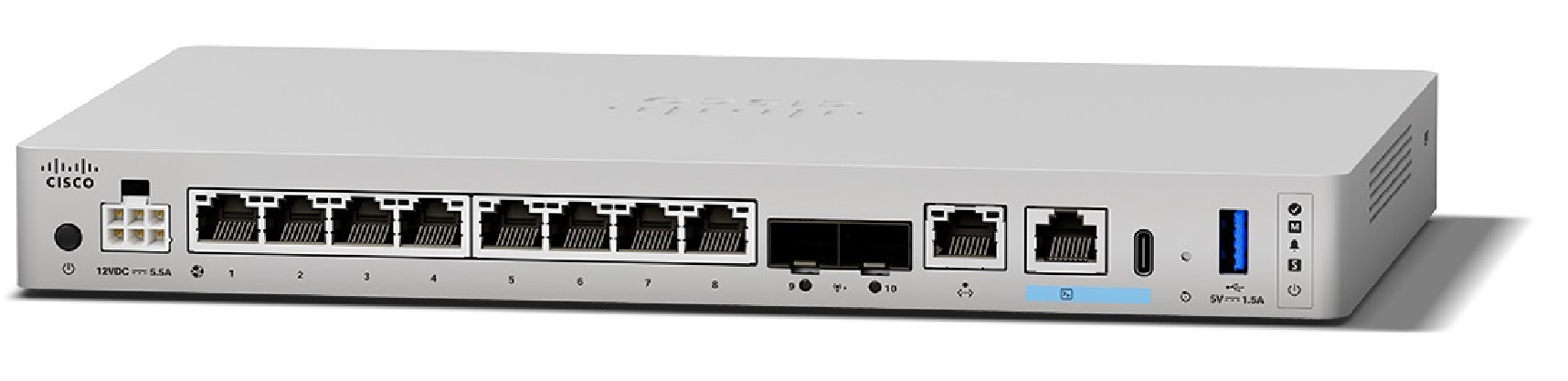
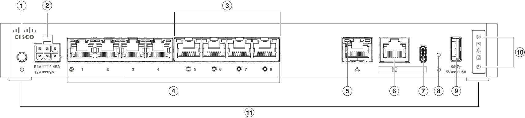
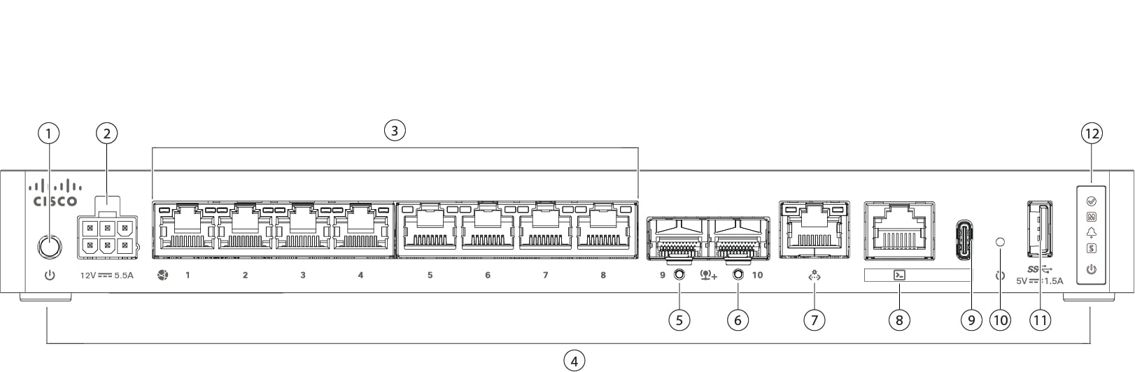
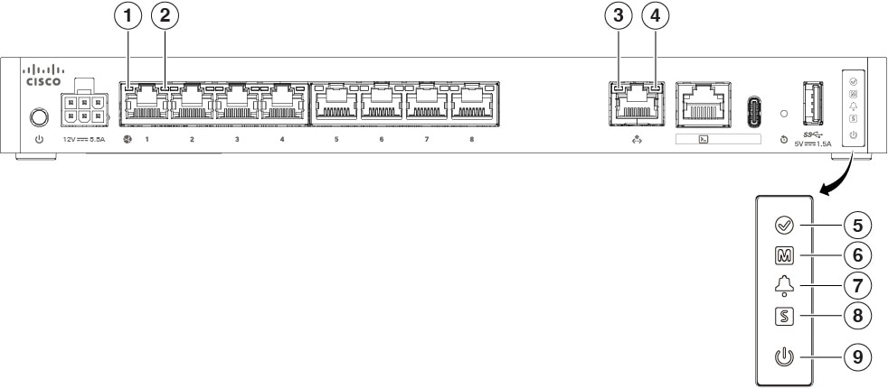
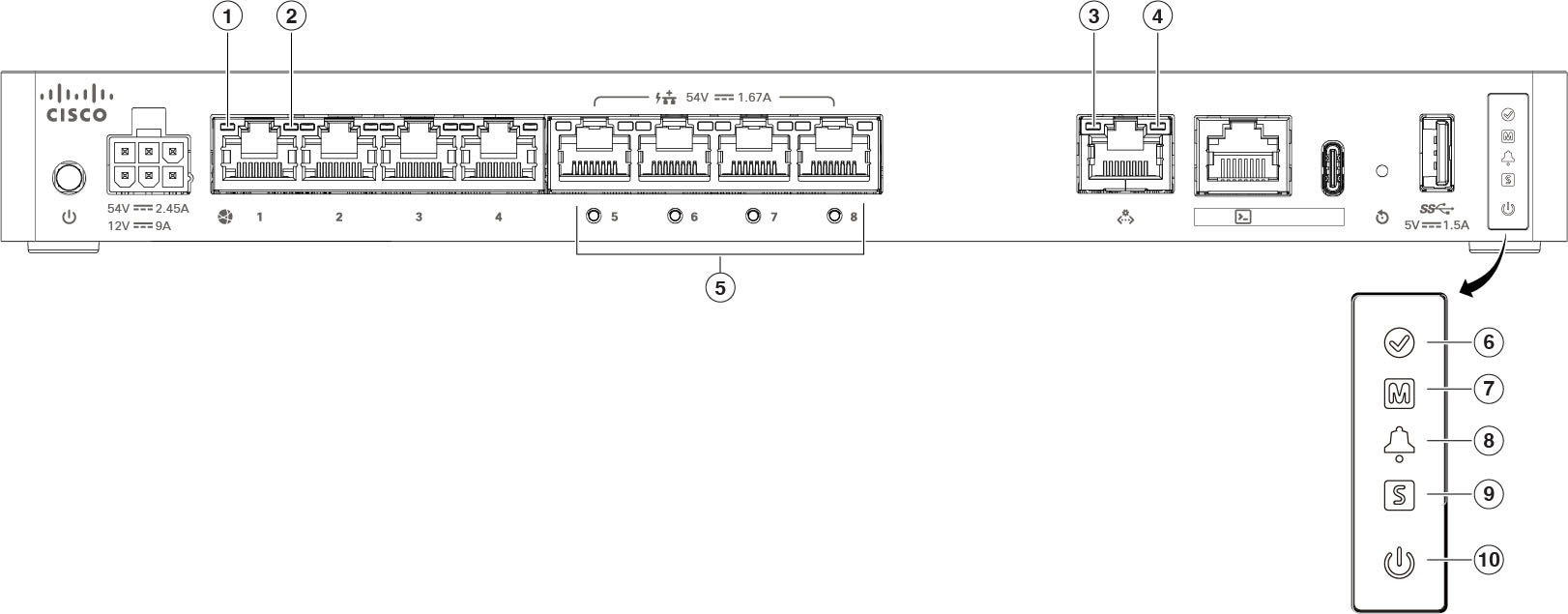
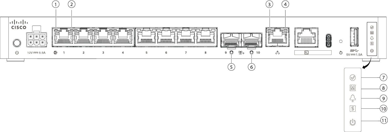
The following figure shows the Secure Firewall 1210CE, 1210CP, and 1220CX.

Figure 1. CSF-1210CE, CSF-1210CP, and CSF-1220CX

The following table lists the features for the Secure Firewall 1210CE, 1210CP, and 1220CX.

Table 1. CSF-1210CE, CSF-1210CP, and CSF-1220CX Features

Feature

CSF-1210CE

CSF-1210CP

CSF-1220CX

Form factor

Compact or 1 RU for the rack shelf

Mounting

  • Desktop mount (default)

  • Wall mount (orderable kit)

  • Rack shelf (orderable kit)

    2-post with rack brackets

Airflow

Right to left (when viewed from the I/O side)

Fan is on the right; pulls in air from the left

System memory

16 GB

Management port

One 1-Gbps Gigabit Ethernet RJ-45 10/100/1000 BaseT

Restricted to network management access; connect with an RJ-45 cable

Console ports

One Cisco Serial (RS-232 on RJ-45)

One USB Type C 2.0

Provides management access through an external system

USB port

One USB Type A 3.0

Used to attach an external device such as storage

Network ports

Eight 1-Gbps copper RJ-45 Gigabit Ethernet ports
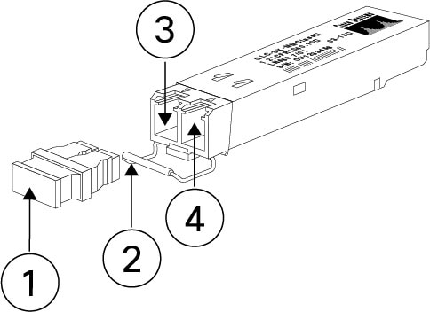
Small form-factor pluggable (SFP)

Not supported

Two 10-Gbps optical Ethernet ports

Supported SFPs

Not supported

See Supported SFP/SFP+/QSFP+ Transceivers for a list of supported 1-Gbps and 10-Gbps SFPs

PoE+ ports

Not supported

4 (Ethernet 1/5 to Ethernet 1/8)

Note


Supports IEEE 802.3at. In threat defense Version 7.6 and ASA Version 9.22 the total system power is capped at 120 W of PoE with a maximum of 30 W per port. You can divide the total 120 W among the four ports evenly.

Not supported

Reset button

Small recessed button

Push and hold with a pin for 5 seconds; resets the chassis to its default state following the next reboot.

Note


Configuration variables are reset to factory default, but the flash is not erased and no files are removed.

Lock slot

Accepts a Kensington T-bar locking mechanism for securing the chassis

Power button

Yes

Located on the left side of the rear panel
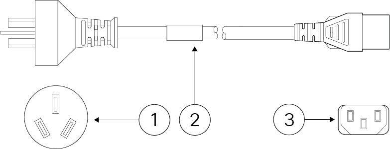
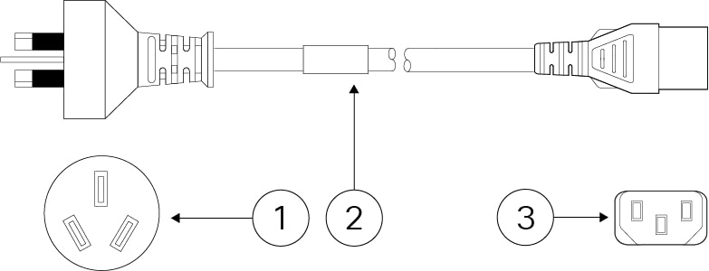
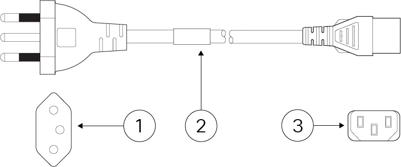
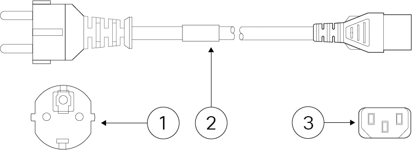
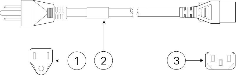
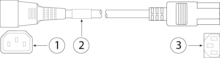
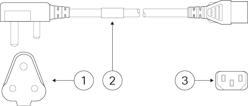
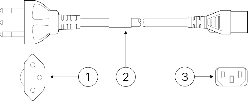
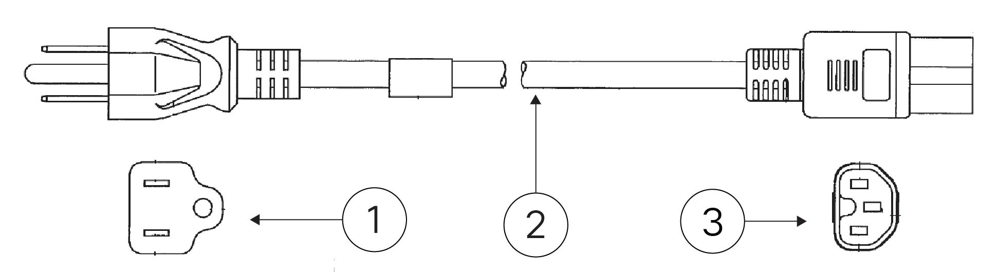
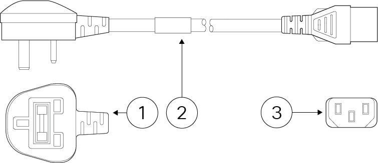
Power cord socket

IEC320-C14

Supports C13 adapter cables

AC power supply

External +12 V at 66 W

External +12 V at 110 W and -54 V at 120 W

External +12 V at 66 W

Storage

480-GB M.2 NVMe

Internal component only; not field-replaceable.

You must return the chassis to Cisco for SSD replacement. See the Cisco Returns Portal for more information.

Fan

One internal blower fan

Internal component only; not field-replaceable. See the Cisco Returns Portal for more information.

Rubber feet

Yes, for stability

PoE Power Supply
The Secure Firewall 1210CP supports PoE and ships with a PoE-supported power supply.

Caution


Do not use the non-PoE power supply with the Secure Firewall 1210CP. If you connect it, the system goes into fail-safe mode, the PoE LEDs blink yellow on the rear panel, and you receive an error message similar to the following:


The PoE module failed to come up. This is due to either a faulty or loose PoE card or an unsupported power supply. Ensure that the supported power supply is connected to rule out any power supply issues. If the problem persists, reach out to the Cisco support team.
The power supplies have a label near the plug that read "POE" and "NON-POE" for easy identification.
Console Ports
The Secure Firewall 1210CE, 1210CP, and 1220CX have two external console ports, a Cisco RJ-45 serial port and a Type C USB serial port. Only one serial console port can be active at a time. When a cable is plugged into the USB console port, the RJ-45 port becomes inactive. Conversely, when the USB cable is removed from the USB port, the RJ-45 port becomes active. The console ports do not have any hardware flow control. You can use the CLI to configure the chassis through either serial console port by using a terminal server or a terminal emulation program on a computer.
  • RJ-45 (8P8C) port—Supports RS-232 signaling to an internal UART controller. The RJ-45 console port does not support a remote dial-in modem. You can use an adapter to convert the RJ45-to-DB9 connection if necessary.

  • Type C USB port—Lets you connect to a USB port on an external computer. You can plug and unplug the USB cable from the console port without affecting Windows HyperTerminal operations. We recommend shielded USB cables with properly terminated shields. The default setting is 9600 baud. Use this for the initial connection. Baud rates for the USB console port are 1200, 2400, 4800, 9600, 19200, 38400, 57600, and 115200 bps.

External Flash Storage
The chassis contains a USB Type A port that you can use to attach an external device. The USB port can provide output power of 5 V and up to a maximum of 1A (5 W of USB power).
  • External USB drive (optional)—You can use the external USB Type A port to attach a data-storage device. The external USB drive identifier is disk1. When the chassis is powered on, a connected USB drive is mounted as disk1 and is available for you to use. Additionally, the file-system commands that are available to disk0 are also available to disk1, including copy, format, delete, mkdir, pwd, cd, and so on.

  • FAT-32 File System—The Secure Firewall 1210CE, 1210CP, and 1220CX only support FAT-32-formatted file systems for the external USB drive. If you insert an external USB drive that is not in FAT-32 format, the system mounting process fails, and you receive an error message. You can enter the command format disk1: to format the partition to FAT-32 and mount the partition to disk1 again; however, data might be lost.

Package Contents

The following figure shows the package contents for the Secure Firewall 1210CE, 1210CP, and 1220CX. Note that the contents are subject to change and your exact contents might contain additional or fewer items.

Figure 2. CSF-1210CE, CSF-1210CP, and CSF-1220CX Package Contents

1

Chassis

2

USB console cable (Type C)

PID: CAB-CONS-USB-C

Optional: in package if ordered

3

Power cord

See Power Cord Specifications for a list of the approved power cords.

4

Power supply

5

Secure Firewall 1210/1220

This document has links to the hardware installation guide, regulatory and safety information guide, and warranty and licensing information. It also contains a QR code and URL that point to the Digital Documentation Portal. The portal contains links to the product information page, the hardware installation guide, the regulatory and safety information guide, the getting started guide, and the zero-touch provisioning guide.

Kensington Lock, Serial Number, and Digital Documentation Portal QR Code Locations

Facing the front panel (non-I/O side) you can find the Kensington lock on the left side of the chassis. It accepts a standard Kensington T-bar locking mechanism for securing the chassis.

The following figure shows the location.

Figure 3. Kensington Lock on the Left Side of Chassis

1

Kensington lock on left side of chassis (facing the front panel, non-I/O side)

The compliance label on the bottom of the chassis contains the chassis serial number, regulatory compliance marks, and the Digital Documentation Portal QR code that points to the getting started guide, the regulatory and compliance guide, the zero-touch provisioning guide, and the hardware installation guide.

The following figure shows an example compliance label found on the bottom of the chassis.

Figure 4. Compliance Label on the Chassis

1

Chassis model number

2

Digital Documentation Portal QR code

3

Chassis serial number

Front Panel

The following figure shows the front panel of the Secure Firewall 1210CE, 1210CP, and 1220CX compact appliances. Note that there are no connectors or LEDs on the front panel.

Figure 5. CSF-1210CE, CSF-1210CP, and CSF-1220CX Front Panel

Rear Panel

The following figures show the rear panels of the Secure Firewall 1210CE, 1210CP, and 1220CX compact appliances. See Rear Panel LEDs for a description of the LEDs.

The following figure shows the rear panel of the Secure Firewall 1210CE.

Figure 6. CSF-1210CE Rear Panel

1

Power button

The power button is a two-position switch. When the switch is sticking out, it's in OFF state and when it is pushed in, it's in the ON state.

2

Power cord socket

3

Ethernet ports 1-8

1G/100M/10M Auto Duplex Auto MDI-X Base-T interfaces

4

Management port

5

Console port RJ-45

6

Console USB Type C port

7

Reset button

8

USB Type A port

9

Status LEDs

10

Rubber feet

The following figure shows the rear panel of the Secure Firewall 1210CP. See Rear Panel LEDs for a description of the LEDs.

Figure 7. CSF-1210CP Rear Panel

1

Power button

The power button is a two-position switch. When the switch is sticking out, it's in OFF state and when it is pushed in, it's in the ON state.

2

Power cord socket

3

PoE Ethernet ports 5-8

4

Ethernet ports 1-8

1G/100M/10M Auto Duplex Auto MDI-X Base-T interfaces

5

Management port

6

Console port RJ-45

7

Console USB Type C port

8

Reset button

9

USB Type A port

10

Status LEDs

11

Rubber feet

The following figure shows the rear panel of the Secure Firewall 1220CX. See Rear Panel LEDs for a description of the LEDs.

Figure 8. CSF-1220CX Rear Panel

1

Power button

The power button is a two-position switch. When the switch is sticking out, it's in OFF state and when it is pushed in, it's in the ON state.

2

Power cord socket

3

Ethernet ports 1-8

1G/100M/10M Auto Duplex Auto MDI-X Base-T interfaces

4

Rubber feet

5

Ethernet port 9 with SFP interface

Supports 1-Gbps/10-Gbps SFPs

6

Ethernet port 10 with SFP interface

Supports 1-Gbps/10-Gbps SFPs

7

Management port

8

Console port RJ-45

9

Console USB Type C port

10

Reset button

11

USB Type A port

12

Status LEDs

Rear Panel LEDs

The LEDs are found on the rear panel of the Secure Firewall 1210C, 1210CP, and 1220CX.

The following figure shows the LEDs on the rear panel of the Secure Firewall 1210C and describes their states.

Figure 9. CSF-1210C Rear Panel LEDs

1

Network

Status of the network ports:

Link status (L):

  • Off—No link, or port is not in use.

  • Green—Link established.

  • Green, flashing—Link activity.

2

Network

Status of the network ports:

Connection-speed status (S):

  • Green, flashing—One flash every three seconds = 10 Mbps.

  • Green, flashing—Two rapid flashes = 100 Mbps.

  • Green, flashing—Three rapid flashes = 1000 Mbps.

3

Management

Status of the management ports:

Link status (L):

  • Off—No link, or port is not in use.

  • Green—Link established.

  • Green, flashing—Link activity.

4

Management

Status of the management ports:

Connection-speed status (S):

  • Green, flashing—One flash every three seconds = 10 Mbps.

  • Green, flashing—Two rapid flashes = 100 Mbps.

  • Green, flashing—Three rapid flashes = 1000 Mbps.

5

Active

Status of the failover pair:

  • Off— Failover is not operational.

  • Green—Failover pair operating normally. The LED is green always unless the chassis in a high availability pair.

  • Amber—When the chassis is in a high availability pair, the LED is amber for the standby unit.

6

Managed Status

  • Green, flashing slowly (twice in 5 seconds)—Cloud is connected.

  • Green and amber, flashing—Cloud connection failure.

  • Green—Cloud is disconnected.

Note

 
The Security Cloud Control (SCC) LED pattern applies to zero-touch provisioning (ZTP). See the Easy Deployment Guide for Cisco Secure Firewall Threat Defense with Cisco Security Cloud Control for more information.

7

Alarm Status

  • Off—No alarms.

  • Amber—Environmental error.

  • Green—Status is ok.

8

Status

System operating status:

  • Off—System has not booted up yet.

  • Green, flashing quickly—System is booting up.

  • Green—Normal system function.

  • Amber—Critical alarm indicating one or more of the following:

    • Major failure of a hardware or software component.

    • Over-temperature condition.

    • Power voltage outside the tolerance range.

9

Power

Power supply status:

  • Off —Power supply off.

  • Green—Power supply on.

  • Green, flashing—System is in the process of a graceful shutdown.

  • Amber—System power is up, system firmware is updating (takes up to 3 minutes), or there is a power fault.

The following figure shows the LEDs on the rear panel of the Secure Firewall 1210CP and describes their states.

Figure 10. CSF-1210CP Rear Panel LEDs

1

Network

Status of the network ports:

Link status (L):

  • Off—No link, or port is not in use.

  • Green—Link established.

  • Green, flashing—Link activity.

2

Network

Status of the network ports:

Connection-speed status (S):

  • Green, flashing—One flash every three seconds = 10 Mbps.

  • Green, flashing—Two rapid flashes = 100 Mbps.

  • Green, flashing—Three rapid flashes = 1000 Mbps.

3

Management

Status of the management ports:

Link status (L):

  • Off—No link, or port is not in use.

  • Green—Link established.

  • Green, flashing—Link activity.

4

Management

Status of the management ports:

Connection-speed status (S):

  • Green, flashing—One flash every three seconds = 10 Mbps.

  • Green, flashing—Two rapid flashes = 100 Mbps.

  • Green, flashing—Three rapid flashes = 1000 Mbps.

5

PoE

Status of the PoE ports:

  • Off—No alarms.

  • Amber—The powered device is in power-deny state.

  • Amber, flashing —If the chassis is connected to an incompatible power supply, the LEDs of all 4 ports flash to show that the device has gone into fail-safe mode.

6

Active

Status of the failover pair:

  • Off— Failover is not operational.

  • Green—Failover pair operating normally. The LED is green always unless the chassis in a high availability pair.

  • Amber—When the chassis is in a high availability pair, the LED is amber for the standby unit.

7

Managed Status

  • Green, flashing slowly (twice in 5 seconds)—Cloud is connected.

  • Green and amber, flashing—Cloud connection failure.

  • Green—Cloud is disconnected.

Note

 
The SCC LED pattern applies to ZTP. See the Easy Deployment Guide for Cisco Secure Firewall Threat Defense with Cisco Security Cloud Control for more information.

8

Alarm Status

  • Off—No alarms.

  • Amber—Environmental error.

  • Green—Status is ok.

9

Status

System operating status:

  • Off—System has not booted up yet.

  • Green, flashing quickly—System is booting up.

  • Green—Normal system function.

  • Amber—Critical alarm indicating one or more of the following:

    • Major failure of a hardware or software component.

    • Over-temperature condition.

    • Power voltage outside the tolerance range.

10

Power

Power supply status:

  • Off —Power supply off.

  • Green—Power supply on.

  • Green, flashing—System is in the process of a graceful shutdown.

  • Amber—System power is up, system firemware is updating (takes up to 3 minutes), or there is a power fault.

The following figure shows the LEDs on the rear panel of the Secure Firewall 1220CX and describes their states.

Figure 11. CSF-1220CX Rear Panel LEDs

1

Network

Status of the network ports:

Link status (L):

  • Off—No link, or port is not in use.

  • Green—Link established.

  • Green, flashing—Link activity.

2

Network

Status of the network ports:

Connection-speed status (S):

  • Green, flashing—One flash every three seconds = 10 Mbps.

  • Green, flashing—Two rapid flashes = 100 Mbps.

  • Green, flashing—Three rapid flashes = 1000 Mbps.

3

Management

Status of the management ports:

Link status (L):

  • Off—No link, or port is not in use.

  • Green—Link established.

  • Green, flashing—Link activity.

4

Management

Status of the management ports:

Connection-speed status (S):

  • Green, flashing—One flash every three seconds = 10 Mbps.

  • Green, flashing—Two rapid flashes = 100 Mbps.

  • Green, flashing—Three rapid flashes = 1000 Mbps.

5

SFP

Status of the SFP:

  • Off—No SFP plugged in or no laser.

  • Green—Link is established.

  • Green, flashing—Link activity.

  • Amber—No link or network failure.

6

SFP

Status of the SFP:

  • Off—No SFP plugged in or no laser.

  • Green—Link is established.

  • Green, flashing—Link activity.

  • Amber—No link or network failure.

7

Active

Status of the failover pair:

  • Off— Failover pair is in standby mode.

  • Green—Failover pair is in active mode and operating normally.

8

Managed Status

  • Green, flashing slowly (twice in 5 seconds)—Cloud is connected.

  • Green and amber, flashing—Cloud connection failure.

  • Green—Cloud is disconnected.

Note

 
The SCC LED pattern applies to ZTP. See the Easy Deployment Guide for Cisco Secure Firewall Threat Defense with Cisco Security Cloud Control for more information.

9

Alarm Status

  • Off—No alarms.

  • Amber—Power supply, fan, or PoE failure.

10

Status

System operating status:

  • Off—System is powered off.

  • Green, flashing—System is booting up.

  • Green—Normal system function.

  • Amber—System book issue.

  • Amber, flashing—Alarm or secure book failure.

    • Major failure of a hardware or software component.

    • Over-temperature condition.

    • Power voltage outside the tolerance range.

11

Power

Power supply status:

  • Off —Power supply off.

  • Green—Power supply on.

  • Green, flashing—System is in the process of a graceful shutdown.

  • Amber—System power is up, system firmware is updating (takes up to 3 minutes), or there is a power fault.

Hardware Specifications

The following table contains hardware specifications for the Secure Firewall 1210CE, 1210CP, and 220CX.

Table 2. CSF-1210CE, CSF-1210CP, and CSF-1220CX Hardware Specifications

Specification

CSF-1210CE

CSF-

1210CP

CSF-1220CX

Chassis dimensions (H x W x D)

1.17 x 10.8 x 6.8 inches

2.819 x 27.432 x 17.272 cm

Note


Excludes rubber feet

Chassis weight

3.04 lb (1.38 kg)

3.17 lb (1.44 kg)

3.09 lb (1.40 kg)

Rack shelf dimensions (H x W x D)

1.7 x 17.3 x 15.7 inches

4.318 x 43.942 x 39.878 cm

System power

40 W maximum power

32 W typical power

Temperature

Operating: 32 to 104°F (0 to 40°C)

Derate the maximum operating temperature 2.7° F (1.5° C) per 1000 ft (304.8 m) above 6,000 ft (1828.8 m) altitude.

Nonoperating: -13 to 158°F (-25 to 70°C)

Nonoperating: Maximum altitude is 15,000 ft (4570 m)

Humidity

Operating: 5 to 85% (noncondensing)

Nonoperating:5 to 95% (noncondensing)

Altitude

Operating: 0 to 10,000 ft (3048 m)

Nonoperating: 0 to 15,000 ft (4570 m)

Acoustic noise

23.5 dBA @ 80.6°F/27°C

42.7 dBA @ maximum fan speed

Supported SFP/SFP+/QSFP+ Transceivers

The SFP/SFP+/QSFP+ transceiver is a bidirectional device with a transmitter and receiver in the same physical package. It is a hot-swappable optical or electrical (copper) interface that plugs into the SFP/SFP+/QSFP+ ports on the fixed ports and the network module ports, and provides Ethernet connectivity.

The 1-Gbps and 10-Gbps transceivers are supported on the fixed ports for the following models and software versions:

  • CSF-1210CE, CSF-1210CP, CSF-1220CX

  • Threat defense Version 7.6 and ASA Version 9.22.1.

See Cisco SFP Modules for Gigabit Ethernet Applications Data Sheet for more information.

The following figure shows the components of a transceiver.

Figure 12. SFP Transceiver

1

Dust plug

2

Bail clasp

3

Receive optical bore

4

Transmit optical bore

Safety Warnings

Take note of the following warnings:


Warning


Statement 1055—Class 1/1M Laser

Invisible laser radiation is present. Do not expose to users of telescopic optics. This applies to Class 1/1M laser products.


Warning


Statement 1056—Unterminated Fiber Cable

Invisible laser radiation may be emitted from the end of the unterminated fiber cable or connector. Do not view directly with optical instruments. Viewing the laser output with certain optical instruments, for example, eye loupes, magnifiers, and microscopes, within a distance of 100 mm, may pose an eye hazard.


Warning


Statement 1057—Hazardous Radiation Exposure

Use of controls, adjustments, or performance of procedures other than those specified may result in hazardous radiation exposure.


Warning


Use appropriate ESD procedures when inserting the transceiver. Avoid touching the contacts at the rear, and keep the contacts and ports free of dust and dirt. Keep unused transceivers in the ESD packing that they were shipped in.


Caution


Although non-Cisco SFPs are allowed, we do not recommend using them because they have not been tested and validated by Cisco. Cisco TAC may refuse support for any interoperability problems that result from using an untested third-party SFP transceiver.


The following table lists the supported 1-Gbps transceivers for the fixed ports (not supported for management port).

Table 3. Supported 1-Gbps SFP Transceivers

Optics Type

PID

Medium

Operating Wavelength (nm)

Maximum Operating Distance

1000Base-T

GLC-T

Cat 5e

328 ft (100 m)

1000Base-T

GLC-TE

Cat 5e

328 ft (100 m)

Multimode

GLC-SX-MMD

multimode

850

1804 ft (550 m)1

Single mode

GLC-LH-SMD

single mode

1310

32,821 ft (10 km)

SM extended

GLC-EX-SMD

single mode

1310

131, 234 ft (40 km)

SM

GLC-ZX-SMD

single mode

1550

229,659 ft (70 km)2

1 Depending on fiber grade and core size, operating distance may vary.
2 Depending on fiber grade and core size, operating distance may vary.

The following table lists the supported transceivers for the fixed ports (not supported for the management port).

Table 4. Supported 10-Gbps SFP Transceivers

Optics Type

PID

Medium

Operating Wavelength (nm)

Maximum Operating Distance

10G-SR

SFP-10G-SR

multimode

850

984 ft (300 m)3

10G-SR

SFP-10G-SR-S

multimode

1310

984 ft (300 m)

10G-LR

SFP-10G-LR

single mode

1310

32,821 ft (10 km)

10G-LR

SFP-10G-LR-S

single mode

850

32,821 ft (10 km)

10G-ER

SFP-10G-ER

single mode

850

131,234 ft (40 km)

10G-ER

SFP-10G-ER-S

single mode

1310

131,234 ft (40 km)

10G-ZR

SFP-10G-ZR

single mode

1550

131,234 ft (40 km)

10G-ZR

SFP-10G-ZR-S single mode

1550

262,467 ft (80 km)

10G DAC copper

SFP-H10GB-CUxM

Length 1, 1.5, 2, 2.5, 3, 4, 5 m

Twinax cable, passive

10G DAC CU active

SFP-H10GB-ACUxM

Length 7, 10 m

Twinax cable, active

10G AOC

SFP-10G-AOCxM

Length 1, 2, 3, 5, 7, 10 m

Active optical cable

3 Depending on fiber grade and core size, operating distance may vary.

Product ID Numbers

The following table lists the field-replaceable PIDs associated with the Secure Firewall 1210CE, 1210CP, and 1220CX compact appliances. The spare components are ones that you can order separately from the appliance. If any internal components fail, you must get a return material authorization (RMA) for the entire chassis. See the Cisco Returns Portal for more information.


Note


See the show inventory command in the Cisco Secure Firewall Threat Defense Command Reference or the Cisco Secure Firewall ASA Series Command Reference to display a list of the PIDs for your Secure Firewall 1210CE, 1210CP, and 1220CX.


Table 5. CSF-1210CE, CSF-1210CP, and CSF-1220CX PIDs

PID

Description

CSF1210CE-ASA-K9

Secure Firewall 1210CE compact desktop appliance, ASA

CSF1210CP-ASA-K9

Secure Firewall 1210CP PoE compact desktop appliance, ASA

CSF1220CX-ASA-K9

Secure Firewall 1220CX compact desktop appliance, ASA

CSF1210CE-TD-K9

Secure Firewall 1210CE compact desktop appliance, NGFW

CSF1210CP-TD-K9

Secure Firewall 1210CP PoE compact desktop appliance, NGFW

CSF1220CX-TD-K9

Secure Firewall 1220CX compact desktop appliance, NGFW

CSF1200C-PWR-AC

Secure Firewall 1210CE and 220CX 66-W AC (12 V) power supply

CSF1200C-PWR-AC=

Secure Firewall 1210CE and 1220CX 66-W AC (12 V) power supply (spare)

CSF1200CP-PWR-AC

Secure Firewall 1210CP 230-W AC power supply (110 W of 12 V and 120 W of -53.5 V)

CSF1200CP-PWR-AC=

Secure Firewall 1210CP 230-W AC power supply (110 W of 12 V and 120 W of -53.5 V) (spare)

CSF1200C-RACK-MNT=

Secure Firewall 1210CE, 1210CP, 1220CX rack-mount kit (spare)

CSF1200C-WALL-MNT=

Secure Firewall 1210CE, 1210CP, 1220CX wall-mount kit (spare)

Power Cord Specifications

Standard power cords or jumper power cords are available for connection to the security appliance. The jumper power cords for use in racks are available as an optional alternative to the standard power cords.

If you do not order the optional power cord with the system, you are responsible for selecting the appropriate power cord for the product. Using a incompatible power cord with this product may result in electrical safety hazard. Orders delivered to Argentina, Brazil, and Japan must have the appropriate power cord ordered with the system.


Note


Only the approved power cords or jumper power cords provided with the chassis are supported.


The following power cords are supported.

Figure 13. Argentina (CAB-ACR)

1

Plug: VA2073

2

Cord set rating: 10 A, 250 V

3

Connector: V1625

Cord length: 2.5 m
Figure 14. Australia/New Zealand (CAB-ACA)

1

Plug: AU10LS3

2

Cord set rating: 10 A, 250 V

3

Connector: V1625

Cord length: 2.5 m
Figure 15. Brazil (CAB-C13-ACB)

1

Plug: NBR 14136

2

Cord set rating: 10 A, 250 V

3

Connector: EL 701B (EN 60320/C13)

Cord length: 2.1 m
Figure 16. China (CAB-ACC)

1

Plug: V3203C

2

Cord set rating: 10 A, 250 V

3

Connector: V1625

Cord length: 2.5 m
Figure 17. Europe (CAB-ACE)

1

Plug: M2511

2

Cord set rating: 16 A, 250 V

3

Connector: V1625

Cord length: 1.5 m
Figure 18. India (CAB-IND-10A)

1

Plug: IA16A3-C

2

Cord set rating: 16 A, 250 V

3

Connector: V1625BS-E

Figure 19. Italy (CAB-ACI)

1

Plug: IT10S3

2

Cord set rating: 10 A, 250 V

3

Connector: V1625

Cord length: 2.5 m
Figure 20. Japan (CAB-C13-C14-2M-JP) PSE Mark

1

IEC 60320-2-2/E

2

Cord set rating: 10 A, 250 V

3

Connector: IEC 60320/C13

Cord length: 2 m

Figure 21. Japan (CAB-JPN-3PIN)

1

Plug: M744

2

Cord set rating: 12 A, 125 V

3

Connector: V1625

Figure 22. Korea (CAB-AC-C13-KOR)

1

Plug: M2511

2

Cord set rating: 10 A, 250 V

3

Connector: V1625

Figure 23. North America (CAB-AC)

1

Plug: PS204

2

Cord set rating: 10 A, 250 V

3

Connector: V1625

Figure 24. Jumper (CAB-C13-C14-2M)

1

IEC 60320/C14G

2

Cord set rating: 10 A, 250 V

3

Connector: IEC 60320/C13

Cord length: 2.5 m

Figure 25. South Africa (AIR-PWR-CORD-SA)

1

Plug: SA16A

2

Cord set rating: 10 A, 250 V

3

Connector: V1625

Figure 26. Switzerland (CAB-ACS)

1

Plug: SW10ZS3

2

Cord set rating: 10 A, 250 V

3

Connector: V1625

Figure 27. Taiwan (CAB-ACTW)

1

Plug: EL 302 (CNS10917)

2

Cord set rating: 10 A, 125 V

3

Connector: EL 701 (EN 60320/C13)

Figure 28. United Kingdom (CAB-ACU)

1

Plug: 3P BS 1363

2

Cord set rating: 10 A, 250 V

3

Connector: IEC 60320/C13