Release Notes for Cisco Video Surveillance Manager, Release 7.11.0
Available Languages
Table of Contents
Release Notes for Cisco Video Surveillance Manager, Release 7.11
Support for the Cisco CSS UCSM5 1RU and 2RU Servers
Upgrade from Older Releases Using Backup and Restore
Cisco 8000 Camera Feature Support
“Unknown” State for Servers in a Transportation Environment
Windows player support for MP4 clip playback
Operator permissions to create or download clips
Support for Axis cameras: P1428, Q1659, Q3708 and P3367
Support for Panoramic Views for Multi-lens Cameras
Zipstream compression support for Axis Cameras
ONVIF Cameras Supporting Motion Detection Events
HTML5 video viewing can be manually enabled
VSOM High Availability Improvements
Audio is Disabled When Using Privacy Mask
H.265 codec in Supported cameras
Cisco Connected Safety and Security UCS Platform Series Servers
Upgrading from Previous Cisco VSM Releases
Supported Devices: Generic IP Cameras
Supported Devices: Analog Cameras
Device Models Validated in Cisco VSM as Generic IP Cameras
Clipping Support By Application
Obtaining and Installing Licenses
Understanding the Cisco VSM Software Types
Using the Software Bug Search Tool
Release Notes for Cisco Video Surveillance Manager, Release 7.11

Note![]() Always refer to the latest online version of these Release Notes for up to date information.
Always refer to the latest online version of these Release Notes for up to date information.
This document provides important information for Release 7.11 of the Cisco Video Surveillance Manager (Cisco VSM).
What’s New in This Release
Cisco VSM Release 7.11 includes the following new features and enhancements:
- Upgrade from Older Releases Using Backup and Restore
- Cisco 8000 Camera Feature Support
- “Unknown” State for Servers in a Transportation Environment
- Windows player support for MP4 clip playback
- Operator permissions to create or download clips
- Support for Axis cameras: P1428, Q1659, Q3708 and P3367
- Support for Panoramic Views for Multi-lens Cameras
- Zipstream compression support for Axis Cameras
- ONVIF Cameras Supporting Motion Detection Events
- HTML5 video viewing can be manually enabled
- VSOM High Availability Improvements
- Audio is Disabled When Using Privacy Mask
- H.265 codec in Supported cameras
- Other Improvements
Support for the Cisco CSS UCSM5 1RU and 2RU Servers
Cisco VSM Release 7.11 and higher supports the following Cisco Connected Safety and Security UCS series servers:
For more information, including detailed specification, ordering information and installation instructions see the following documentation:
Cisco Connected Safety and Security UCS Platform Series Data Sheet
Cisco Connected Safety and Security UCS Platform Series Data Sheet |
Detailed specifications, descriptions and model comparisons. |
|
Cisco Connected Safety and Security UCS Platform Series Servers: |
Instructions to install and set up the Cisco VSM server appliance deployed on the Cisco Connected Safety and Security UCS Platform Series servers: The user guide also describes how to create a recovery flash drive for Cisco VSM on the Cisco CSS UCSM5 1RU and 2RU servers. |
|
Instructions to install, upgrade, and recover the various software components used in a Cisco Video Surveillance deployment. |
||
Cisco Video Surveillance Manager Release 7 Server Performance Guidelines |
Describes the core capabilities and performance of a supported Video Surveillance Manager server for use when designing and deploying Cisco Physical Security solutions. This document provides the scalability limits for server platforms supported in Cisco Video Surveillance Release 7.0.1 and higher. |
For more information, see the Cisco UCS C-Series Server Documentation Roadmap.
Upgrade from Older Releases Using Backup and Restore
Beginning with Cisco VSM release 7.11, you can upgrade directly to the new release using the backup and restore method if the servers in your deployment are running system software more than 2 releases older than the current release.
For example, backup a release 7.8 server and restore it to a new release 7.11 server.
1.![]() Install a new physical or virtual server running the latest Cisco VSM release.
Install a new physical or virtual server running the latest Cisco VSM release.
2.![]() Backup the old server configuration and data.
Backup the old server configuration and data.
3.![]() On the new server, restore server services backup file (such as Federator, VSOM, Media Server, Map or Metadata).
On the new server, restore server services backup file (such as Federator, VSOM, Media Server, Map or Metadata).
–![]() Uncheck the option Include System Configuration. This option must be deselected for server services restore.
Uncheck the option Include System Configuration. This option must be deselected for server services restore.
4.![]() On the new server, restore the CDAF backup files.
On the new server, restore the CDAF backup files.
–![]() Check the option Include System Configuration. This will change the IP address and other network configurations to the same as the old server.
Check the option Include System Configuration. This will change the IP address and other network configurations to the same as the old server.
5.![]() After the servers are upgraded, you must upgrade the cameras, encoders, and monitoring workstations (PCs) to the supported release.
After the servers are upgraded, you must upgrade the cameras, encoders, and monitoring workstations (PCs) to the supported release.
Note![]() This method is supported when upgrading to Cisco VSM release 7.11 or later.
This method is supported when upgrading to Cisco VSM release 7.11 or later.
The following table describes the upgrade methods based on how old your server’s current release is.
Cisco 8000 Camera Feature Support
The following features can now be managed using Cisco VSM on Cisco 8000 cameras:
- Enable for edge storage continuous recording on SD cards and auto merge (similar to Cisco 6XXX cameras).
- Enable for event based recording. Events are recorded on the camera and then copied on to the Media Server.
- Set the time zone.
- Manage camera apps including install, uninstall, enable, and disable. Users can also configure camera app events and receive notifications on Cisco VSM generated by the apps.
“Unknown” State for Servers in a Transportation Environment
The “Unknown” icon  is displayed at the location level if all primary Media Servers at that location are unreachable (Figure 1). This indicates that the cameras and encoders supported by those servers are not available. Cameras and encoders associated with the unreachable server(s) will also display the “Unknown” icon
  .
.
This allows operators who view video in mobile environments (such as trains) to know that the cameras at a location (such as on a train) are unavailable, even though the camera itself may be healthy.
For example, if a train is represented by a location, operators can see if the Media Server is powered up by looking at the location tree. If all primary Media Servers at that location are unreachable, cameras on that train also display the “Unknown” icon  .
.
Figure 1 Unknown State in a Transportation Environment
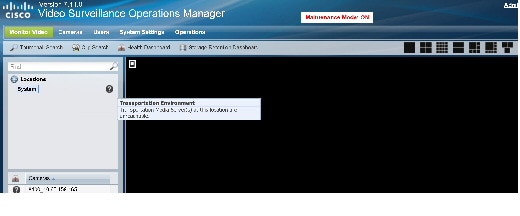
This feature can be turned on or off by a Cisco VSM administrator.
Step 1![]() Indicate that the Cisco VSM deployment is a transport environment:
Indicate that the Cisco VSM deployment is a transport environment:
a.![]() Go to System Settings > Settings.
Go to System Settings > Settings.
b.![]() Select Transport Environment from the General tab.
Select Transport Environment from the General tab.
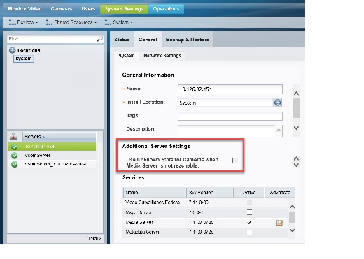
Step 2![]() Enable the Unknown state for specific Media Servers:
Enable the Unknown state for specific Media Servers:
a.![]() Go to System Settings > Servers.
Go to System Settings > Servers.
c.![]() In the General > System tab, select Use Unknown State for Cameras when Media Server is not reachable (Figure 2).
In the General > System tab, select Use Unknown State for Cameras when Media Server is not reachable (Figure 2).
Figure 2 Server Setting: Enable Unknown State
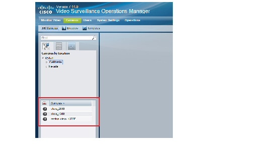
Step 4![]() Locations where all primary Media Servers are unreachable display the “Unknown” icon
Locations where all primary Media Servers are unreachable display the “Unknown” icon  (Figure 1). All the cameras assigned to that server are also shown in the “Unknown” state (Figure 3).
Figure 3 Cameras in the Unknown State
Windows player support for MP4 clip playback
Cisco VSM clips in MP4 format can be saved with the Advanced Audio Coding (AAC) codec for audio playback in various players, such as the Windows Media Player.
Select the option Convert Audio to ACC codec when saving MP4 clips in the Operations Manager, ActiveX or Cisco SASD.
Operator permissions to create or download clips
There are now separate operator permissions to Create Clip and Export Clips. For example, you can allow users to create but not download a clip.
- When you select Create Clips, View Recordings is also selected.
- When you select Export Clips, Create Clips is also selected.
- If you upgrade a server from release 7.10 or earlier to release 7.11, any role with the permission to Export Recordings will now have both Create Clip and Export Clips permissions.
Support for Axis cameras: P1428, Q1659, Q3708 and P3367
Support is added for Axis camera models P1428, Q1659, Q3708 and P3367. See Supported Devices: Axis for more information.
The Axis P1428E supports resolutions in 5MP, QHD and UHD modes.
- The Axis Q1659 supports resolutions in 4K, 11MP and 20MP modes.
- Automatic mode change via VSOM is not supported. First configure the capture mode on the camera, create a camera template on VSOM with the resolution supported in the mode, and then add the camera in VSOM with the new template.
- Capture mode with max FPS support should be set on camera. For example, in a camera where 1080p resolution is supported in 4K with 25 fps, 11MP with 15fps and 20MP with 8fps, to stream 1080p, capture mode on the camera should be set to 4K.
AXIS Q3708-PVE is a fixed dome with multiple sensors network camera.
- This camera has three sensors which give a 180º panoramic view with smooth capture of movements at up to 30 fps in 3× Quad HD or 20 fps in 3× 5 MP resolution.
- This camera should be added as an Encoder and the three lenses to be added as Axis Analog Cameras The model is “axisanalog”.
- Automatic mode changes via VSOM are not supported. To configure the resolutions supported in a particular mode, first change the mode from camera and then create the template for analog camera.
VSM 7.11.0 supports full resolutions for Axis P3367 fixed dome network camera.
Support for Panoramic Views for Multi-lens Cameras
Panoramic multi-lens cameras allows operators to view live video and recorded video from a multi-lens camera so that all images are stitched together in a continuous layout.
You can also create CVA clips from multi-lens panoramic cameras that appear as a single image. Clips in other formats cam be created for a single pane only.
- Arecont AV12186
- Arecont AV20185
- Arecont AV23065
- Arecont AV8185
- Arecont AV8365
- Axis M3007
- AXIS Q3708-PVE
- Panasonic SW 458
- Panasonic SF 438
- Sony HM662
- Bosch FLEXIDOME IP 7000MP Panoramic
- Thumbnail Search and Clip Search only display video from a single lens, not the entire panoramic image.
- CVA clips can be created for the panoramic image. MP4 and virtual clips are not supported.
- You can create CVA, MP4 or virtual clips from a single lens image. Click any lens image to enlarge the view and access the controls.
- Create the camera template that defines the camera settings. All lenses for a panoramic camera must be assigned to the same template or only a single video pane will be displayed.
- Align the camera lenses as necessary to create the desired image. For example, make sure they are aligned to create a seamless video image. See the camera documentation for more information.
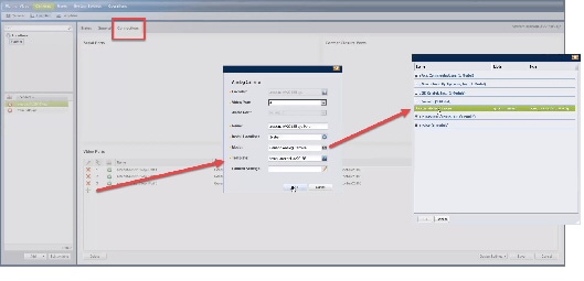
To add a panoramic camera, add the camera as an encoder, then add each lens on an encoder port.
Step 1![]() Log on to the Operations Manager.
Log on to the Operations Manager.
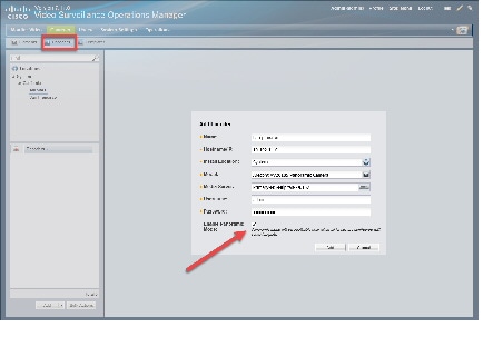
Step 2![]() Add the camera as an encoder:
Add the camera as an encoder:
d.![]() Enter the device Name, IP Address, and Install Location, Media Server, Username and Password.
Enter the device Name, IP Address, and Install Location, Media Server, Username and Password.
e.![]() For Model, select a supported panoramic camera.
For Model, select a supported panoramic camera.
f.![]() Select the Enable Panoramic Mode check box (Figure 1-4).
Select the Enable Panoramic Mode check box (Figure 1-4).
–![]() This appears only for supported panoramic camera models.
This appears only for supported panoramic camera models.
–![]() If this is not selected, only video from a single lens will be displayed.
If this is not selected, only video from a single lens will be displayed.
–![]() This setting is also displayed under the encoder General > Lens Settings, which allows you to enable or disable it after the camera is added (as an encoder).
This setting is also displayed under the encoder General > Lens Settings, which allows you to enable or disable it after the camera is added (as an encoder).
Figure 1-4 Add a Panoramic Camera as an Encoder
Step 3![]() Add the camera lenses to the encoder ports (Figure 1-5).
Add the camera lenses to the encoder ports (Figure 1-5).
Be sure to assign the correct lens to the correct encoder port. If the images appear out of order, revise the ports that the lenses are assigned to.
b.![]() Under Video Ports, click the Add
Under Video Ports, click the Add  icon.
icon.
c.![]() Enter the analog camera settings:
Enter the analog camera settings:
The template that defines the camera settings. All lenses for a panoramic camera must be assigned to the same template or only a single video pane will be displayed. Note Templates define attributes such as video quality and schedules. Only templates that support the camera are displayed. See the “Adding and Editing Camera Templates” section for more information. |
Figure 1-5 Add Panoramic Camera Lenses as Encoder Ports
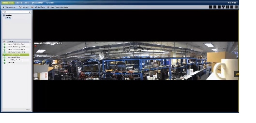
Step 4![]() To view the panoramic video:
To view the panoramic video:
a.![]() Click Monitor (Figure 1-6).
Click Monitor (Figure 1-6).
b.![]() Select the camera location.
Select the camera location.
c.![]() Each lens appears as a camera entry in Cisco VSM. Click any lens from the camera to view the full panoramic image.
Each lens appears as a camera entry in Cisco VSM. Click any lens from the camera to view the full panoramic image.
–![]() If only a single lens image appears, check the encoder configuration to make sure panoramic mode is enabled, the lenses are assigned to encoder ports, and all lenses are assigned to the same template.
If only a single lens image appears, check the encoder configuration to make sure panoramic mode is enabled, the lenses are assigned to encoder ports, and all lenses are assigned to the same template.
–![]() If the images are out of order, reassign them to the correct encoder port.
If the images are out of order, reassign them to the correct encoder port.
–![]() If the images are not aligned, adjust them in the camera according to the manufacturer instructions.
If the images are not aligned, adjust them in the camera according to the manufacturer instructions.
Figure 1-6 Monitor Video from a Panoramic Camera

Step 5![]() View the panoramic video (Figure 1-6).
View the panoramic video (Figure 1-6).
b.![]() Select the camera location.
Select the camera location.
c.![]() Each lens appears as a camera entry in Cisco VSM. Click any lens from the camera to view the full panoramic image.
Each lens appears as a camera entry in Cisco VSM. Click any lens from the camera to view the full panoramic image.
–![]() If only a single lens image appears, check the encoder configuration to make sure panoramic mode is enabled, the lenses are assigned to encoder ports, and all lenses are assigned to the same template.
If only a single lens image appears, check the encoder configuration to make sure panoramic mode is enabled, the lenses are assigned to encoder ports, and all lenses are assigned to the same template.
–![]() If the images are out of order, reassign them to the correct encoder port.
If the images are out of order, reassign them to the correct encoder port.
–![]() If the images are not aligned, adjust them in the camera according to the manufacturer instructions.
If the images are not aligned, adjust them in the camera according to the manufacturer instructions.
Figure 1-7 Monitor Video from a Panoramic Camera
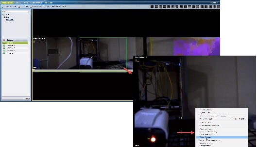
d.![]() (Optional) Select a single lens to enlarge the image, then right-click to access additional options such as Select Streams (Figure 1-8).
(Optional) Select a single lens to enlarge the image, then right-click to access additional options such as Select Streams (Figure 1-8).
–![]() Right click and select Switch to panoramic view to display all lens images.
Right click and select Switch to panoramic view to display all lens images.
e.![]() (Optional) Create CVA clips from the panoramic image.
(Optional) Create CVA clips from the panoramic image.
f.![]() (Optional) Create CVA, MP4 or virtual clips from the single lens image.
(Optional) Create CVA, MP4 or virtual clips from the single lens image.
–![]() The MP4 and virtual clip options are enabled for single-lens mode only, not for the full panoramic image.
The MP4 and virtual clip options are enabled for single-lens mode only, not for the full panoramic image.
Figure 1-8 Pop-up Menu for a Single Lens Image
Zipstream compression support for Axis Cameras
Zipstream compression technology can be configured on Axis Cameras using the Operations Manager.
- Axis Q1659
- Axis Q3708
- Axis cameras added with model AXIS Generic VAPIX 3.0 Network Camera (axis generic)
- Zipstream settings configured using the camera UI will be overridden by the VSOM Zipstream settings.
- By default, Zipstream is set to Off in the HML template settings for the supported cameras.
- Dynamic FPS for Zipstream is not supported. It will automatically be set to off when Zipstream is enabled in a template.
- Configuring axis cameras with Zipstream results in reduced average bit rates. On Storage Retention Dashboard, in CBR mode, the “Estimated storage (by configured settings)” for these cameras might be higher than the “Estimated Storage (by actual observation)”
- Cameras added using the 'axisgeneric' model may or may not support Zipstream. Please note the following when using Zipstream with the axisgeneric driver.
–![]() For Zipstream unsupported cameras, Zipstream values in the template should be set to off.
For Zipstream unsupported cameras, Zipstream values in the template should be set to off.
–![]() For Zipstream supported cameras, please check the camera documentation for valid Zipstream values.
For Zipstream supported cameras, please check the camera documentation for valid Zipstream values.
For example Zipstream strength “Higher” and “Extreme” is supported only for cameras with firmware version 6.30 or later. If you set these values for unsupported cameras, the template settings will save successfully, but the camera might not stream using those settings.
Create a new camera template with the Zipstream setting
Step 1![]() Log on to the Operations Manager.
Log on to the Operations Manager.
Step 2![]() Select Cameras > Templates.
Select Cameras > Templates.
Step 3![]() Click Add to create a new template.
Click Add to create a new template.
Step 4![]() Select a Zipstream supported model, such as axisq1659. axisq3708 or axisgeneric.
Select a Zipstream supported model, such as axisq1659. axisq3708 or axisgeneric.
Step 5![]() Select the Streaming, Recording and Event tab.
Select the Streaming, Recording and Event tab.
Step 6![]() Click Custom in the Video Quality field.
Click Custom in the Video Quality field.
Step 7![]() Enter the Zipstream settings:
Enter the Zipstream settings:
- Off: Disabled
- Low, Medium, High, Higher, Extreme: Increasing the strength reduces the bit rate but will also affect the visual image quality. At value Low, visual image quality is not affected, but as the strength increases, visual image quality is degraded in unprioritized image areas, for example the background. Image details important for forensic video analysis are kept.
- Dynamic GOP: Enables GOP length variation between 1 (GOP length set on H.264 tab) and 300 (max dynamic GOP below)
- Max dynamic GOP length : Enter 1 to 1200.
ONVIF Cameras Supporting Motion Detection Events
Vivotek ONVIF cameras support motion detection events in Cisco VSM release 7.11 and later, but the motion windows must be configured directly on the camera using the camera UI before the camera is configured using Cisco VSM.
Only the following ONVIF cameras support motion detection.
–![]() Models FD8167A, FD8369A-V, FD8177-H, IB8367A, IB8369A, SD9161-H, SD9363-EH
Models FD8167A, FD8369A-V, FD8177-H, IB8367A, IB8369A, SD9161-H, SD9363-EH
Complete the following steps in order:
 to enable or disable the alerts that are generated when a motion stop or start event occurs.
See the camera documentation and the Cisco Video Surveillance Operations Manager User Guide for more information.
HTML5 video viewing can be manually enabled
HTML5 based video streaming is disabled by default in Cisco VSM release 7.11 and higher. To enable HTML5 video monitoring, click the  icon in the top right and click OK to confirm. Click the icon again
  to disable HTML5 video monitoring.
Step 1![]() Log on to the Cisco VSM Operations Manager.
Log on to the Cisco VSM Operations Manager.
Step 2![]() If prompted, accept the security certificate.
If prompted, accept the security certificate.
Step 4![]() Click the HTML5 icon
Click the HTML5 icon  in the top right and click OK when prompted
 to disable HTML5 video monitoring.
- If you click Cancel, the VLC browser plug in will be used instead. If the plug-in is not installed, video will not be displayed.
Step 5![]() (Optional) Select a layout to view multiple panes, or click View Menu to select a pre-defined View.
(Optional) Select a layout to view multiple panes, or click View Menu to select a pre-defined View.
Step 6![]() Expand the location tree and drag a camera onto a viewing pane.
Expand the location tree and drag a camera onto a viewing pane.
VSOM High Availability Improvements
A Media Server is now required for the Split Brain Configuration when setting up Operations Manager HA (VSOM HA).
In addition, the Cisco VSM Management Console can now be used to clear split brain issues on a server.
For example, when the communication link between the servers is reestablished, log in to the Operations Manager using the virtual IP/host name, and verify that the Peer server is reachable. If the Peer server is reachable, you must return the server to a normal state by doing the following:
You can clear the split brain issue using either the Operations Manager or the Cisco VSM Management Console.
To use the Console to clear a split brain issue:
Step 1![]() Correct the issue causing the loss of communication between the Master and Peer servers.
Correct the issue causing the loss of communication between the Master and Peer servers.
Step 2![]() Log in to the Cisco VSM Management Console.
Log in to the Cisco VSM Management Console.
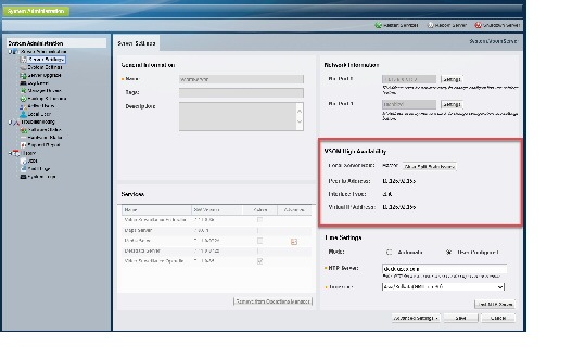
Step 3![]() Select Server Administration > Server Settings (Figure 9).
Select Server Administration > Server Settings (Figure 9).
Step 4![]() Under VSOM High Availability, click Clear Split Brain Issues.
Under VSOM High Availability, click Clear Split Brain Issues.
Step 5![]() Click OK and verify the alert and issue are cleared.
Click OK and verify the alert and issue are cleared.
Step 6![]() Replace the HA configuration on the Peer server with the Master server’s configuration.
Replace the HA configuration on the Peer server with the Master server’s configuration.
Figure 9 VSOM High Availability
Audio is Disabled When Using Privacy Mask
In Cisco VSM release 7.11 and higher, audio is also disabled when using the privacy mask feature.
When the Privacy Mask is enabled on a compatible camera, all live video and audio from that camera is blocked and cannot be viewed by any operator or monitor, or recorded by the Cisco Video Surveillance system. This feature is typically used with the “Virtual Sitter” feature for health care providers, allowing operators to temporarily block video from a Cisco Video Surveillance camera when the patient requires privacy.
- You must belong to a User Group with Control Privacy Mask access permissions to use this feature.
- If privacy mask is enabled:
–![]() The camera template audio settings cannot be changed.
The camera template audio settings cannot be changed.
–![]() The following options are disabled: Reset Status, Replace Configuration, Replace camera, synchronization.
The following options are disabled: Reset Status, Replace Configuration, Replace camera, synchronization.
–![]() Edge recording for audio does not stop when privacy mask is enabled.
Edge recording for audio does not stop when privacy mask is enabled.
- If Privacy Mask is enabled on any encoder port, you cannot add new encoder ports to the configuration.
- If the connection between the Operations Manager and the Media Server is poor, the privacy mask setting will not be applied to camera.
- Cisco cameras. See Supported Devices: Cisco for the specific models
- Axis F44 Encoder
- Axis P3365 added as AXIS Generic VAPIX 3.0 Network Camera(axisgeneric)
H.265 codec in Supported cameras
The High Efficiency Video Coding (HEVC) compression codec, also known as H.265, is supported in the following cameras. The H.265 codec is configured by default for these cameras, including the Low, Medium and High settings for Stream A and Stream B.
See Change the Codec for a Camera to change the codec.
- Cisco 8000P
- Cisco 8020
- Cisco 8030
- Cisco 8400
- Vivotek SD9361-EHL
- Vivotek SD9362-EH/Vivotek SD9362-EHL
- Support for H.265 live and recorded video in the 64-bit AX Video Client, VSOM and SASD (the 32 bit ActiveX client is not supported)
- Play, Pause, Seek video support for H.265 in the AX Video Client, VSOM and SASD
- Playback across gaps in H.265 and transitions between H.265, H.264 and MJPEG
- Forward, Reverse playback with speed control
- SASD Lite and Video Wall support for H.265
- Media Server support for LTS with H.265
- Support for Media Server camera-level streaming and recording redundancy
- Dynamic Proxy
- Economical Streaming
Change the Codec for a Camera
To change the codec for a specific camera, use the Custom quality settings for stream A or B.
Step 1![]() Log on to the Operations Manager.
Log on to the Operations Manager.
Step 2![]() Select Cameras > Cameras.
Select Cameras > Cameras.
Step 3![]() Select a location and camera:
Select a location and camera:
Step 4![]() Click the Streaming, Recording and Events tab.
Click the Streaming, Recording and Events tab.
Step 5![]() Select Custom for stream A or B to display the Custom Quality Setting.
Select Custom for stream A or B to display the Custom Quality Setting.
Step 6![]() Next to Codec, select H.265, H.264 or another codec.
Next to Codec, select H.265, H.264 or another codec.
Step 8![]() Wait for the Job to complete.
Wait for the Job to complete.
Change the Codec Used By a Template
Change the codec for a camera template to apply the change to multiple cameras.
Step 1![]() Log on to the Operations Manager.
Log on to the Operations Manager.
Step 2![]() Select Cameras > Templates.
Select Cameras > Templates.
Step 3![]() Edit or add a template:
Edit or add a template:
Step 4![]() Enter or revise the General settings and select a supported camera.
Enter or revise the General settings and select a supported camera.
Step 5![]() Click the Streaming, Recording and Events tab.
Click the Streaming, Recording and Events tab.
Step 6![]() Select Custom for stream A or B to display the Custom Quality Setting.
Select Custom for stream A or B to display the Custom Quality Setting.
Step 7![]() Next to Codec, select H.265, H.264 or another codec.
Next to Codec, select H.265, H.264 or another codec.
Step 8![]() Click Create, Save or Save As.
Click Create, Save or Save As.
Step 9![]() Wait for the Job to complete.
Wait for the Job to complete.
Step 10![]() Assign cameras to the template.
Assign cameras to the template.
Important Notes
Virtual Machine Installation
An.OVA template file is used to install a new virtual machine (VM) instance of the server. See Cisco Video Surveillance Virtual Machine Deployment and Recovery Guide for UCS Platforms for more information.
Getting Started
Cisco VSM Release 7.11 is pre-installed on new servers, can be installed as a virtual machine, or used to upgrade an existing deployment.
Release 7.11 is pre-installed in new installations on the Cisco Connected Safety and Security UCS Platform Series servers: |
See Cisco Connected Safety and Security UCS Platform Series Servers for more information. |
|
Direct upgrades can be performed from the previous 2 releases. Older releases require alternative methods. Upgrades can be performed on Cisco VSM virtual machines (VMs) and on Cisco Video Surveillance servers. |
||
An.OVA template file is used to install a new virtual machine (VM) instance of the server. |
After an.OVA virtual machine is installed, you can use the Cisco VSM Management Console to perform future upgrades of the system software. See Cisco Video Surveillance Virtual Machine Deployment and Recovery Guide for UCS Platforms for more information. |
See the following for more information:
- Cisco Video Surveillance Manager: Install and Upgrade Guide
- Cisco Connected Safety and Security UCS Platform Series Servers
- Upgrading from Previous Cisco VSM Releases
- Recovery/Factory Image
Cisco Connected Safety and Security UCS Platform Series Servers
Cisco VSM Release 7.11 is pre-installed on new installations of the Cisco Connected Safety and Security UCS Platform Series when ordered with the Cisco VSM software installed.
- Cisco CSS UCS Server User Guide — supported features, physical installation and setup instructions
- Release Notes for the Cisco CSS UCS Servers
- After the server appliance is installed, see the Cisco Video Surveillance Manager: Install and Upgrade Guide to perform the initial Cisco VSM setup.
- For additional server hardware documentation, see the Cisco UCS C-Series Server Documentation (Roadmap).
Upgrading from Previous Cisco VSM Releases
For complete instructions, see the Cisco Video Surveillance Manager: Install and Upgrade Guide.
The following table describes the upgrade methods based on how old your server’s current release is.
Directly upgrade the system software on the server using a Upgrades can be performed on Cisco VSM virtual machines (VMs) and on Cisco Video Surveillance servers. Supported Cisco Connected Safety and Security UCS series servers include: |
||
Backup and restore to a new server For example, backup the configuration and data from a release 7.8 server and restore it to a new release 7.11 server. |
Cisco Video Surveillance Manager: Install and Upgrade Guide |
|
For older releases, first upgrade to 7.6 then upgrade to latest version. |
- Release 7.0 was pre-installed on the Cisco Multiservices Platform (Cisco MSP) servers, including the CPS-MSP-1RU-K9 and CPS-MSP-2RU-K9.
- Release 7.2 to Release 7.7 was pre-installed on the CPS-UCS-1RU-K9 and CPS-UCS-2RU-K9 Cisco Connected Safety and Security UCS series servers.
–![]() The CIVS platform is not supported and cannot be upgraded to VSM 7.7 or later.
The CIVS platform is not supported and cannot be upgraded to VSM 7.7 or later.
- Release 7.7 to 7.11 is also pre-installed on the Cisco Connected Safety and Security UCS series servers:
–![]() CPS-UCSM4-1RU-K9 / Cisco CPS UCSM4 2RU
CPS-UCSM4-1RU-K9 / Cisco CPS UCSM4 2RU
- Release 7.11 and higher is also pre-installed on the Cisco Connected Safety and Security UCS series servers:
–![]() KIN-UCSM5-1RU-K9 / KIN-UCSM5-2RU-K9
KIN-UCSM5-1RU-K9 / KIN-UCSM5-2RU-K9
Note![]() Virtual Machine (VM) installations can also be upgraded using the Cisco VSM Management Console. Upgrades are supported from release 7.8 or higher on the RHEL6 operating system. See Cisco Video Surveillance Virtual Machine Deployment and Recovery Guide for UCS Platforms for more information.
Virtual Machine (VM) installations can also be upgraded using the Cisco VSM Management Console. Upgrades are supported from release 7.8 or higher on the RHEL6 operating system. See Cisco Video Surveillance Virtual Machine Deployment and Recovery Guide for UCS Platforms for more information.
Recovery/Factory Image
You can also create a bootable USB flash drive that can be used to recover an installation or perform a a factory installation of Cisco VSM Release 7.11 on a supported physical server that shipped with Cisco VSM Release 7.11 pre-installed. This includes:
For more information, see Cisco Video Surveillance Manager: Install and Upgrade Guide
Released Versions
Cisco VSM Release 7.11 is released with 7.11.0-146i. The component package versions are:
- Cisco_AMQBroker-7.11.0-1.noarch
- Cisco_MetaDataService-7.11.0-088d.i686
- Cisco_VSTools-7.11.0-088d.i686
- Cisco_GeoServer-7.8.0-1.noarch
- Cisco_Tomcat-7.0.82-3.el6.noarch
- Cisco_VSMUpgrade-7.11.0-088d.i686
- Cisco_VSRecorder-7.11.0-088d.i686
- Cisco_VSDrivers-7.11.0-088d.i686
- Cisco_SASD-7.11.0-40.noarch
- Cisco_DashCast-7.11.0-088d.i686
- Cisco_CDAF-7.11.0-101.noarch
- Cisco_VSF-7.11.0-101.noarch
- Cisco_VSBase-7.11.0-088d.i686
- Cisco_VSMS-7.11.0-088d.i686
- Cisco_MPClient-7.11.0-55.noarch
- Cisco_VSOM-7.11.0-101.x86_64
Supported Devices
The following sections provide information about the devices that this version of Cisco VSM supports:
- Supported Devices: Cisco
- Supported Devices: Arecont
- Supported Devices: Axis
- Supported Devices: IQinVision
- Supported Devices: Mobotix
- Supported Devices: Panasonic
- Supported Devices: Pelco
- Supported Devices: Sony
- Supported Devices: Vivotek
- Supported Devices: Generic IP Cameras
- Supported Devices: Analog Cameras
- Device Models Validated in Cisco VSM as Generic IP Cameras
Supported Devices: Cisco
Table 6 through Table 12 provide information about Cisco devices supported in this release:
- Cisco 2400/2500, 2600, 2800, and 2900 Series Basic functionality such as streaming and recording is supported. Any features that require a firmware upgrade are not supported.
- Cisco 3000 Series
- Cisco 4000 Series and 5000 Series Basic functionality such as streaming and recording is supported. Any features that require a firmware upgrade are not supported.
- Cisco 6000 Series
- Cisco 7000 Series
- Cisco 8000 Series
- Cisco CIVS-SENC-4P and CIVS-SENC-8P
|
FW Version for Release 7.11 Compatibility
1
|
||||||||||
|---|---|---|---|---|---|---|---|---|---|---|
|
FW Version for Release 7.11 Compatibility
2
|
||||||||||
|---|---|---|---|---|---|---|---|---|---|---|
|
FW Version for Release 7.11 Compatibility
3
|
||||||||||
|---|---|---|---|---|---|---|---|---|---|---|
|
FW Version for Release 7.11 Compatibility
4
|
||||||||||
|---|---|---|---|---|---|---|---|---|---|---|
|
FW Version for Release 7.11 Compatibility
5
|
||||||||||
|---|---|---|---|---|---|---|---|---|---|---|
|
FW Version for Release 7.11 Compatibility
9
|
||||||||||
|---|---|---|---|---|---|---|---|---|---|---|
Additional Notes on Cisco Devices
- Cisco 4500 and 4500E support video analytics.
- Redundancy is supported for all Cisco devices some exceptions for the 2400, 2500, 2900 and 5000 series. The 2400, 2500, 2900 and 5000 series do not support sending events to the redundant server such motion detection and contact closure events.
- Cisco 5000 series does not support motion detection at video bit-rates above 4,000 (4 Mbps). The “H” video preset in Templates has been chosen to not exceed this, so motion detection will work.
- The Cisco 5000 and 2900 camera series do not allow changes to the authentication settings (username/password) or networking settings (DHCP/Static, DNS, etc.) through Cisco VSM. These values can only be changed using the camera web interfaces.
- Focus, Auto Focus and Zoom support are not available for Cisco 6000P, 3421V, 3520, 3530, 3535, and 3050 camera models.
- When Cisco VSM manages a Cisco 6930, 2830, or 2835 camera, it automatically enables the HTTP protocol on the camera and uses this protocol to send PTZ commands to the camera. Other configuration commands continue to use the HTTPS protocol.
- The Cisco 2830, 2835, 3000 series, 6000 series and 7030 cameras now support MJPEG primary streams.
- Cisco 3421V and 6050 cameras do not support Contact Closure, Cisco 7030 camera supports 3 input ports. All other Cisco 3000, 6000, 8000 series cameras support 1 input port.
- In PTZ Tour Configuration, the configured transition time configured includes the time that it takes the camera to move from the one preset position to the next preset position in addition to the time that the camera is expected to stay in the preset position. If the transition time is configured to a value that is less than the time that it takes the camera to move from one preset position to the next, the camera moves between the first and second presets positions only, instead of touring between all preset positions that are configured in the tour.
- The minimum firmware version required to support camera applications is 2.5.0-10.
- The minimum firmware version required to support connected edge storage is 2.0.
Supported Devices: Arecont
Table 13 provides information about Arecont devices that this Cisco VSM release supports.
Additional Notes on Arecont Devices
- AV20185, AV20365, AV12186, AV8365 and AV8185 are 4-channel IP cameras. In order to support multiple video channels from a single device, Cisco VSM 7 models these devices as “Encoders”.
- Arecont devices have not yet been qualified to support redundancy in Cisco VSM 7.
- Secondary streams are not supported in H, M, L template settings for Arecont Devices. However secondary stream can be configured using Custom templates.
- Arecont cameras divide the Maximum FPS the camera supports by the number of streams. This could result in lower FPS when both primary and secondary streams are configured for these cameras.
- Arecont AV10XX5, AV5115, AV2115 support VBR and multicast streaming.
- There is a restriction with motion detection for Arecont multi-sensor cameras. False motion events are generated if both half and full resolution size images are requested simultaneously using Cisco VSM or Arecont Camera Web Interface or a third party Media Player.
Supported Devices: Axis
Table 14 , Table 15 , and Table 16 provide information about Axis devices supported in this release.
|
Version
10
|
||||||||||
|
Version
11
|
||||||||||
Table 16 provides information about additional Axis devices that this Cisco VSM release supports.
Additional Notes on Axis Devices
- Axis P3301 IP camera and Q7401, Q7404, and Q7406 encoders have been qualified to support redundancy in Cisco VSM 7.0.1.
- Axis 233D supports contact closure configuration and events.
- Support for 0.1fps MJPEG stream for all supported Axis models.
The following table documents the various Field-Of-Views supported for the Axis M3007 panoramic cameras and support for PTZ and Motion Detection for these Field-Of-Views.
The Axis M3007 camera allows the user to configure various mounting options directly in the camera web interface that affects the possible values for Field-Of-Views that can be configured on the camera. The table below provides this mapping:
Supported Devices: IQinVision
Table 19 provides information about IQinVision devices that this Cisco VSM release supports.
Supported Devices: Mobotix
Table 20 provides information about Mobotix devices that this Cisco VSM release supports.
Supported Devices: Panasonic
Table 21 provides information about Panasonic devices that this Cisco VSM release supports.
Additional Notes on Panasonic Devices
- Panasonic devices have not yet been qualified to support redundancy in Cisco VSM 7.
- Only same field of views can be configured on primary and secondary streams on Panasonic cameras SW458/SF438.
- The following table documents the various Field-Of-Views supported for the Panasonic SF 458 and SF 438 panoramic cameras and support for PTZ and Motion Detection for these Field-Of-Views.
Supported Devices: Pelco
Table 23 provides information about Pelco devices that this release supports.
Additional Notes on Pelco Devices
- Pelco devices have not yet been qualified to support Redundancy in Cisco VSM 7.
- Audio volume controls are not supported for NET540XT
- For Pelco NET540xT PTZ to work, the analog camera should be chosen as Pelco Analog Camera (pelco_sarix) in Operations Manager and not as Pelco D.
- The user needs to directly configure the Serial protocol on the Pelco NET540XT encoder outside of Cisco VSM.
- The Pelco Spectra IV TXB-N (H.264 capable model) run Pelco Sarix firmware and can be supported in Cisco VSM as a Pelco Sarix Generic IP camera (additional details in the Generic IP camera section).
Supported Devices: Sony
Table 24 provides information about Sony devices that this release supports.
Additional Notes on Sony Devices
- Sony devices have not yet been qualified to support redundancy in Cisco VSM 7.
- These Sony devices do not support motion detection with the H.264 media type.
- The Sony SNC-RX5x0 cameras stop streaming video when the Object Detection window is opened in the camera’s web interface.
- For Sony HM662 Panoramic camera, only the 360 degree view is supported. De-warped views are not supported.
Supported Devices: Vivotek
Table 25 provides information about Vivotek devices that this release supports.
Supported Devices: Generic IP Cameras
Cisco VSM Release 7.11 provides the following device drivers to support IP cameras from various vendors. The functionality they support will depend on the particular device that they are used with. They are intended to provide a quick and easy way to support devices for which there isn’t yet a specific driver available for Cisco VSM. Since these drivers may not be tested with a specific device, some issues may be encountered. When using these drivers with a device, failover and redundancy are not supported.
Note![]() The vendor specific generic driver should always be used before a non-vendor specific driver such as ONVIF.
The vendor specific generic driver should always be used before a non-vendor specific driver such as ONVIF.
|
Motion Detection
14
|
||||||||
|---|---|---|---|---|---|---|---|---|
- Supports only IP Cameras, no support for Encoders
- No contact closure support
- Multicast streaming is supported only for the primary stream
- Multicast port must be an even number within the range 16000:19999
- Audio Multicast issues are observed on most of the ONVIF cameras. Hence do not enable audio when multicast is enabled for video.
- Capture Mode on the camera cannot be changed using ONVIF APIs. So, it is assumed that the camera is in the desired capture mode before adding it to VSOM using ONVIF
- This ONVIF driver has been tested with a limited number of camera models from Axis, Sony, Panasonic, Bosch, Pelco, Samsung, J2000IP, Hikvision and Cohu. We have found that these cameras have some variations in how they have implemented the ONVIF specification. Hence there may be compatibility issues when using this ONVIF driver with a particular device that is ONVIF compliant.
- Some of the known caveats are listed below:
- ONVIF user account—Some Axis cameras require a special ONVIF user account, which can be created on the camera's web interface before adding an AXIS ONVIF camera to the VSOM. This page is at Setup --> System Options --> Security --> ONVIF --> Add
- Camera and VSMS (Media Server) Time Synchronization—ONVIF camera and VSMS server to which ONVIF camera is being added should have their time synchronized ideally using NTP.
- Codec Change through VSOM—Hikvision camera requires a reboot after the codec is changed from VSOM.
- The Minimum Firmware Version of Hikvision cameras supported is V5.3.0, to be added as ONVIF camera in Cisco VSM.
- Megapixel Mode setting on the camera SND-7080
- To support the resolutions (1600*1200) and (2048*1536), change the Megapixel Mode to 3-Megapixel in the following page on the camera browser: Settings -> Audio & Video -> video profile -> Megapixel mode
- Enable Authentication on the camera before adding it to VSOM In the camera browser, go to Camera Setup -> Configuration -> User Settings. Select User and enable “Require Password” field.
- Media Transport Type— Only UDP is supported. Streaming fails if TCP is selected.
- Unsupported Resolutions —Streaming fails for the resolutions 176*144, 176*120, 160*120
- Codec Change through VSOM— Switching from H264 to JPEG or vice-versa requires a camera reboot. And camera needs to be deleted and added in VSOM after camera is up.
- Support for Audio— Camera does not support ONVIF Audio
- Frame rate— Only Framerate 30 is supported
- Dual Streaming— Secondary configuration overwrites the primary configuration. So, dual streaming is not supported on Bosch cameras using ONVIF.
- Capture Mode Setting— If the camera is added in VSOM using Multicast, changing the capture mode on the camera browser manually causes the streaming to fail. After this, only the unicast streaming works
- User Authentication— User Authentication should be enabled in the camera browser as follows - Setup -> User mng -> User auth. Choose ON for User auth.
- Media Transport Type— Only UDP is supported. Streaming fails if TCP is selected
- Support for Audio— Camera does not support ONVIF Audio
- Set Configuration Issues — Camera returns success even if one or more of the parameters are not valid for that camera/video stream. ONVIF profile gets updated with values but Camera still uses the previous correct value. Recommend to configure only the values as allowed in the camera browser.
- Support for Password change on the camera— Camera does not support password change for the administrator users using ONVIF API.
Supported Devices: Analog Cameras
This Cisco VSM release provides support for the following analog cameras.
Device Models Validated in Cisco VSM as Generic IP Cameras
The camera models listed in Table 28 have been tested with VSM Release 7.11 as generic IP cameras.
Clipping Support By Application
You can create and view video clips using the following Cisco VSM applications:
Note![]() When converting a virtual clip to an MP4 file, only the entire duration of the virtual clip can be saved, not a segment.
When converting a virtual clip to an MP4 file, only the entire duration of the virtual clip can be saved, not a segment.
Obtaining and Installing Licenses
To install a license, purchase the license and obtain the license file, then upload the file to the Operations Manager.
Table 30 lists the part numbers for the Cisco VSM licenses. Multiple camera and VSMS licenses can be included in a single license file. For example, a single license file might include support for 25 additional cameras and two additional VSMS devices.
- A license for 10,000 Cisco cameras is included by default (you do not need to purchase and install an additional license for Cisco cameras).
- You can add 1 Media Server and 10 non-Cisco cameras without a license for initial setup purposes only. This feature is removed when you add any permanent license.
Step 1![]() Purchase additional licenses:
Purchase additional licenses:
a.![]() Determine the part number for the license you want to purchase (see Table 30 ).
Determine the part number for the license you want to purchase (see Table 30 ).
b.![]() Purchase the license by contacting your Cisco sales representative or any Cisco reseller. For more information, visit http://www.cisco.com/en/US/ordering/index.shtml.
Purchase the license by contacting your Cisco sales representative or any Cisco reseller. For more information, visit http://www.cisco.com/en/US/ordering/index.shtml.
c.![]() When the purchase is complete, you are issued a Product Authorization Key (PAK) in paper form, or in an e-mail message.
When the purchase is complete, you are issued a Product Authorization Key (PAK) in paper form, or in an e-mail message.
Step 2![]() Obtain the license file:
Obtain the license file:
a.![]() Locate the Product Authorization Key (PAK) that was created with the purchase.
Locate the Product Authorization Key (PAK) that was created with the purchase.
b.![]() In a web browser, open the Cisco Product License Registration web page.
In a web browser, open the Cisco Product License Registration web page.
http://www.cisco.com/go/license/
c.![]() Follow the on-screen instructions to complete the form and enter the Product Authorization Key (PAK). When you are done, a license file with the extension
Follow the on-screen instructions to complete the form and enter the Product Authorization Key (PAK). When you are done, a license file with the extension.lic is sent to your e-mail address.
d.![]() Transfer the file to the drive of the PC used for the configuration.
Transfer the file to the drive of the PC used for the configuration.
Step 3![]() Install the license file in Cisco VSM:
Install the license file in Cisco VSM:
a.![]() Log in to the Operations Manager.
Log in to the Operations Manager.
b.![]() Select System Settings > Software Licensing.
Select System Settings > Software Licensing.
c.![]() Click Add and select the license file located on your local drive.
Click Add and select the license file located on your local drive.
d.![]() Click Save to install the file and activate the additional capacity.
Click Save to install the file and activate the additional capacity.
The additional capacity is available immediately. You do not need to restart the server or take additional steps.
See the Cisco Video Surveillance Operations Manager User Guide for more information.
Understanding the Cisco VSM Software Types
Table 31 describes the different types of software and firmware that are installed on servers, cameras, and encoders.
System software denotes the Cisco VSM software, including Media Server, Operations Manager, Cisco VSM Management Console, Safety and Security Desktop and Multipane clients. All servers running the Operations Manager and associated Media Server services must run the same software version. Use the Operations Manager to update the System Software on all servers (such as Media Servers) associated with the Operations Manager. See the Cisco Video Surveillance Operations Manager User Guide for instructions.
|
|
OVF template files are used to install the system software as a virtual machine (VM) on a supported Cisco Unified Computing System (UCS) platform.
|
|
Use the USB Recovery Disk image to create a Cisco VSM 7 Recovery Flash Drive (for example, on a USB stick). The recovery disk can be used do the following:
See the Cisco Video Surveillance Manager Recovery Guide (Cisco Connected Safety and Security UCS Platform Series) for more information. |
|
Device firmware is provided by the device manufacturer. The firmware for Cisco devices can be upgraded using Operations Manager. Firmware for other manufacturers is upgraded using a direct connection. See the “Upgrading Camera and Encoder Driver Firmware” section of the Cisco Video Surveillance Operations Manager User Guide for instructions to upgrade Cisco device firmware, or refer to the device documentation. |
|
Device driver packs are the software packages used by Media Servers and the Operations Manager to interoperate with video devices, such as cameras. Driver packs are included with the Cisco VSM software, or may be added to a server at a later time to add support for new devices or features.
– – Note We strongly recommend upgrading driver packs using the Operations Manager interface (see the “Driver Pack Management” section of the Cisco Video Surveillance Operations Manager User Guide). This allows you to upgrade multiple servers at once. |
|
Language packs can be added to display the Cisco VSM user interfaces in non-English languages. Language packs are added using the Operations Manager (release 7.6 and higher). See the Cisco Video Surveillance Operations Manager User Guide for instructions. |
Obtaining Cisco VSM Software
Complete the following procedure to obtain software and other information for the Cisco VSM products and components:
Step 1![]() Go to the Cisco Video Surveillance Manager product page.
Go to the Cisco Video Surveillance Manager product page.
Step 2![]() Click Download Software.
Click Download Software.
Step 3![]() Select a product category. For example:
Select a product category. For example:
- Video Surveillance Device Driver
- Video Surveillance Manager Stand-alone Tools
- Video Surveillance Media Server Software (including system software)
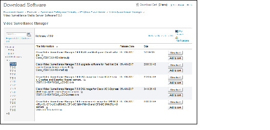
Step 4![]() Select the release for your server, device, or deployment (Figure 10).
Select the release for your server, device, or deployment (Figure 10).
Step 5![]() Click Download or Add to Cart and follow the onscreen instructions.
Click Download or Add to Cart and follow the onscreen instructions.
Figure 10 Download Software Page
You can also navigate the Cisco Physical Security product pages to download software updates and other information:
Step 1![]() Go to the following URL.
Go to the following URL.
http://www.cisco.com/go/physicalsecurity
Step 2![]() Click View All Physical Security Products.
Click View All Physical Security Products.
Step 3![]() Click IP Video Surveillance.
Click IP Video Surveillance.
Step 4![]() Click Cisco Video Surveillance Manager.
Click Cisco Video Surveillance Manager.
Step 5![]() Click Download Software for this Product.
Click Download Software for this Product.
Step 6![]() Click a Software Type and follow the onscreen instructions.
Click a Software Type and follow the onscreen instructions.
For example: Video Surveillance Media Server Software (Figure 10).
Step 7![]() Select the release for your server, device, or deployment.
Select the release for your server, device, or deployment.
Step 8![]() Click Download or Add to Cart and follow the onscreen instructions.
Click Download or Add to Cart and follow the onscreen instructions.
Caveats
This section includes the following topics:
Using the Software Bug Search Tool
You can use the Bug Search Tool to find information about most caveats for Cisco VSM releases, including a description of the problems and available workarounds. The Bug Search Tool lists both open and resolved caveats.
To access Bug Search Tool, you need the following items:
To use the Software Bug Search Tool, follow these steps:
Step 1![]() To access the Bug Search Tool, go to https://tools.cisco.com/bugsearch/
To access the Bug Search Tool, go to https://tools.cisco.com/bugsearch/
Step 2![]() Log in with your Cisco.com user ID and password.
Log in with your Cisco.com user ID and password.
Step 3![]() To look for information about a specific problem, enter the bug ID number in the Search for field.
To look for information about a specific problem, enter the bug ID number in the Search for field.
Step 4![]() For more information, go to the Bug Search interactive tour.
For more information, go to the Bug Search interactive tour.
Open Caveats
Table 32 lists caveats that are open in this release.
Resolved Caveats
Table 33 lists caveats that are resolved in this release.
Related Documentation
See the following locations for the most current information and documentation:
Cisco Video Surveillance 7 Documentation Roadmap
Descriptions and links to Cisco Video Surveillance documentation, server and storage platform documentation, and other related documentation.
http://www.cisco.com/go/physicalsecurity/vsm/roadmap
Cisco Physical Security Product Information:
www.cisco.com/go/physicalsecurity/
Cisco Video Surveillance Manager Documentation Website
www.cisco.com/go/physicalsecurity/vsm/docs
Cisco and the Cisco logo are trademarks or registered trademarks of Cisco and/or its affiliates in the U.S. and other countries. To view a list of Cisco trademarks, go to this URL: www.cisco.com/go/trademarks. Third-party trademarks mentioned are the property of their respective owners. The use of the word partner does not imply a partnership relationship between Cisco and any other company. (1721R)
Any Internet Protocol (IP) addresses and phone numbers used in this document are not intended to be actual addresses and phone numbers. Any examples, command display output, network topology diagrams, and other figures included in the document are shown for illustrative purposes only. Any use of actual IP addresses or phone numbers in illustrative content is unintentional and coincidental.
 Feedback
Contact Cisco
- Open a Support Case

- (Requires a Cisco Service Contract)