Release Notes for Cisco Video Surveillance Manager, Release 7.10
Available Languages
Table of Contents
Release Notes for Cisco Video Surveillance Manager , Release 7.10
Display Text and Time in a Cisco Camera’s Video View
Save Alert Filters in Cisco SASD
Security Event Notification by Camera
Storage Retention and Recording Dashboard
Using the Actual Bitrate to Estimate Storage
View Storage and Bitrate Information in the Storage Retention Dashboard
How disk space is estimated using VBR
Configure Storage Retention Status Warnings and Emails
Mark and Search Video Streams Using Cisco SASD
Support for Cisco and Vivotek Cameras, and Axis Encoder
Exclude Padding from On-Demand Recordings
Support for Additional Axis Cameras and Encoders
Supported SSL cipher algorithms
Cisco Connected Safety and Security UCS Platform Series Servers
Upgrading from Previous Cisco VSM Releases
Related Recovery Documentation
Supported Devices: Generic IP Cameras
Supported Devices: Analog Cameras
Device Models Validated in Cisco VSM as Generic IP Cameras
Clipping Support By Application
Obtaining and Installing Licenses
Understanding the Cisco VSM Software Types
Using the Software Bug Search Tool
Release Notes for Cisco Video Surveillance Manager, Release 7.10

Note Always refer to the latest online version of these Release Notes for up to date information.
This document provides important information for Release 7.10 of the Cisco Video Surveillance Manager (Cisco VSM).
What’s New in Release 7.10
Cisco VSM Release 7.10 includes the following new features and enhancements:
- Health Dashboard Improvements
- Display Text and Time in a Cisco Camera’s Video View
- Save Alert Filters in Cisco SASD
- Security Event Notification by Camera
- Storage Retention and Recording Dashboard
- Mark and Search Video Streams Using Cisco SASD
- Support for Cisco and Vivotek Cameras, and Axis Encoder
- Exclude Padding from On-Demand Recordings
- Support for Additional Axis Cameras and Encoders
- Support for JRE 1.8
- Get Custom Resolution API
- Covert Cameras
- Supported SSL cipher algorithms
- Other Improvements
Health Dashboard Improvements
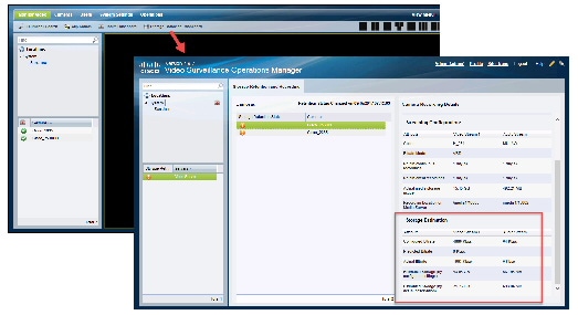
The Health Dashboard has been enhanced to provide an overall snapshot of the servers, cameras and encoders in your deployment. You can view overall information, information about a specific device, or the estimated number of cameras that can be added to a Media Server, and other information.
Step 1 Click Operations > Health Dashboard .
Step 2 Choose a location to view a summary of the health issues at that location, including its sub-locations.
Step 4 Select the Servers, Cameras or Encoders tab for more information.
Note Only camera specific templates are supported when calculating the number of cameras can be added.
Servers
The Overall Status is a graphical representation of the servers at the selected location including the device health status.
Select a server to view additional details, including:
- Storage—The total storage and used storage on the server.
- Existing Camera Count—The number of cameras currently added on the server.
- Server Type—VSOM/ Primary Media Server/ Map Server/ Metadata Server.
- Location—The location where this server is installed.
- Camera Estimation—The approximate number of camera’s that can be added on this Media Server. Select a pre-defined device template. The camera count is estimated based on the template’s recording configurations and the free space available on the selected server.
Note: Estimated camera count is calculated based on the valid file types and formats (.smd, .mp4) stored in the /media repository If the media repository contains unsupported file types, then the space consumed by these files will not be factored in while calculating the estimated cameras that can be added. In addition, if the recordings for certain cameras are shelved, then the algorithm will consider the space occupied by the recordings of those cameras until the time the recording state was moved to shelved. If the recording state of those cameras are altered at a later date, then “Camera Count” estimation will have to be re-run or else going with the old camera estimated count will have an impact on the number of cameras that can be added, and could result in recordings getting groomed.Cameras
The Overall Status is a graphical representation of the cameras at the selected location including the device health status.
Encoders
The Overall Status is a graphical representation of the device at the selected location including health status.
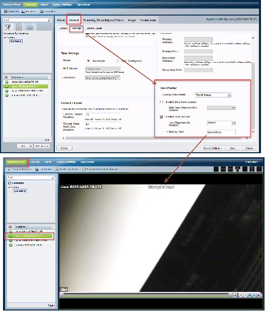
Display Text and Time in a Cisco Camera’s Video View
You can now display custom text or a timestamp in the camera’s live and recorded video view. This information allows users to better identify the camera and current time and date.
Note This feature is supported by Cisco cameras only.
Step 1 Log on to the Operations Manager.
Step 4 In the General > Settings tab, enter the following Text Overlay settings (Figure 1).
- Overlay placement—Display the text or time at the top or bottom of the video image.
- Enable Date/Time Display—Select or deselect to display or hide the timestamp.
– Date/Time Alignment In Overlay—Select Left/Center/Right.
– Text Alignment In Overlay—Select Left/Center/Right.
– Display Text—Enter the text to be displayed in the camera’s video view. A maximum of 26 characters are allowed. Enter only letters and numbers. Special (such as spaces and dashes) characters are not allowed.

Tip Use bulk actions to apply the settings to multiple cameras. Go to Cameras > Bulk Actions and filter the results. Select one or more Cisco Cameras and click Bulk Actions > Camera Settings. Create a setting with a text overlay or select an existing setting.
Save Alert Filters in Cisco SASD
You can save alert filters for future use in Cisco SASD, allowing you to quickly perform the same search.
Step 1 Launch the Cisco SASD application and log in.
Step 2 Select the Alert workspace (Figure 2).
Step 3 Use the filters to narrow the results, and click Apply.
For example, select the Security category to display only security alerts such as motion stop and start events.
Step 4 Click Save to save the filter for future use.
Step 5 Enter a filter name and click Save.
Step 7 Click My Filters to view and select a previously saved filter.
Figure 2 Saved Filters in Cisco SASD
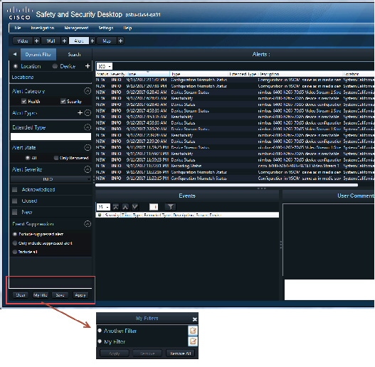
Tip To rename or delete a saved filter, click My Filters and select the edit icon. Change the name and click Apply, or click Remove.
Step 1 Select the Alert workspace (Figure 2).
Step 2 Click My Filters, select a filter and click Apply.
Step 3 Modify the filter settings and click Save.
Step 4 You will be prompted to modify the existing filter or save the settings as a new filter.
Security Event Notification by Camera
Alert Emails (Notification Policies) can now be created for cameras, allowing you to create the same policy for multiple cameras at different locations.
You can also include a snapshot of the event in the email.
Step 1 Verify that the SMTP server settings are configured correctly in the Operations Manager server (under the Advanced
icon).
Step 2 Configure Alerts (using the Advanced Alert feature). See “Using Advanced Events to Trigger Actions” in the Cisco Video Surveillance Operations Manager User Guide for more information.
Step 3 Enable continuous recording on the camera(s).
Step 4 Select Operations > Notification Policies .
Step 7 For Security, select By Camera.
Step 8 Enter the notification settings.
Step 10 Create additional entries for additional locations, cameras, and recipients, if necessary.
The maximum number of policies is 1000.
Overview
A new Storage Retention Dashboard displays your cameras’ estimated storage requirements based on the cameras’ actual bitrate. You can also configure this actual bitrate value in a camera template so Cisco VSM can more accurately estimate the associated camera’s storage requirements. This ensures that Cisco VSM can utilize all available disk space for adding cameras and recording video.
For example, the Storage Retention Dashboard in Figure 3 shows that the estimated storage needed by a camera (based on the configured settings) is almost twice the estimated storage based on the actual video being recorded.
- Estimated Storage (by configured settings)—43.65 GB
- Estimated Storage (by actual observation)—21.26 GB
This is because the camera is configured for VBR, and the configured VBR bitrate used to estimate disk usage is over twice the actual bitrate being used by the camera. To correct the discrepancy so Cisco VSM can accurately estimate the camera’s storage use, enter the actual bitrate in the camera template’s Predicted Bitrate setting.
Figure 3 Storage Retention Dashboard
Using the Actual Bitrate to Estimate Storage
To improve the estimated storage accuracy for your cameras, enter the actual bitrate into a camera template’s Predicted Bitrate field. Cisco VSM will calculate the estimated storage capacity based on this Predicted Bitrate.
If the Predicted Bitrate field is blank, the configured CBR or VBR bitrate is used.

Caution Use the Predicted Bitrate only if you have measured the camera’s average bit rate over a considerable period of time. Providing an incorrect value could either lead to records getting groomed before the retention time or restrict the number of cameras that can be added to your deployment.
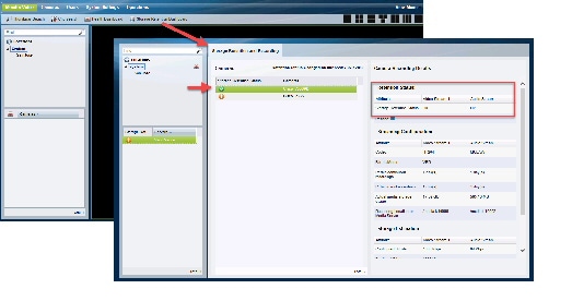
Step 1 Copy the actual bitrate used by the camera (Figure 4).
b. Click Storage Retention Dashboard.
e. Under Storage Estimation, copy the Actual Bitrate.
Figure 4 Actual Bitrate in the Storage Retention Dashboard
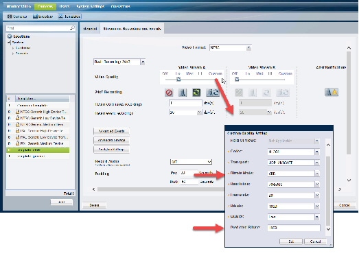
Step 2 Enter the actual bitrate into the Predicted Bitrate field (Figure 5) .
a. Select Cameras > Templates .
c. Next to Video Quality, click Custom.
d. Next to Bit rate mode, verify that VBR is selected.
e. In the Predicted Bitrate field, paste the actual bitrate copied from the Storage Retention Dashboard.
h. The estimated storage needs of the cameras associated with the template will be recalculated based on the Predicted Bitrate value.
Figure 5 Configure VBR Predicted Bitrate
Step 3 Verify that Storage Retention Dashboard warning is cleared (Figure 6) .
b. Click Storage Retention Dashboard.
c. Select a Media Server and select the camera.
d. Verity that the status icon is green.
e. Verify that Storage Retention Status is “OK”.
View Storage and Bitrate Information in the Storage Retention Dashboard
Use the Storage Retention Dashboard to view the estimated and actual bitrates for a camera, and the estimated storage use.
Step 1 Log in to the Cisco VSM Operations Manager.
Step 3 Click Storage Retention Dashboard.
Step 4 Select a Media Server and select a camera.
- Retention Status—Warnings are displayed if the deviation goes above or below the specified percentage (defined in Configure Storage Retention Status Warnings and Emails).
- Streaming Configuration—The camera configuration details, such as Bitrate mode (CBR or VBR) and Codec (H264 or MULAW). The actual disk space used by the camera is also displayed.
- Storage Estimation—
– The configured bitrate vs. the actual bitrate. The Predicted Bitrate shows a value only if entered in the camera template (see Using the Actual Bitrate to Estimate Storage).
– The estimated storage is also displayed
- Review details such as the “Estimated Storage (by configured settings)” vs. the “Estimated Storage (by actual observation)”. The “Estimated Storage (by configured settings)” is adjusted if a Predicted Bitrate is entered (see Using the Actual Bitrate to Estimate Storage).
Usage Notes
- Storage retention is supported only for continuous recordings. However the user will also be able to view storage retention statistics for continuous + motion based recordings. The data will be accurate as long as the camera performs continuous recording. However when motion events occur there will be a significant deviation in the data as it is hard to predict the number of motion events.
- Retention Status Changed on mm/dd/yyyy hh:mm:ss indicates the last date and time stamp when the storage retention status changed for any camera associated with the selected Media Server.
- The supported Codecs are H264 (video) and MULAW (audio).
- The estimated storage is calculated every 30 minutes.
- If a camera configuration is changed, it may take some time (based on the retention period) to estimate and reflect the correct value of “Estimated Storage (by configured settings)”.
- If recording gaps or packet loss occurs during streaming, the calculated estimated storage or calculated bitrate may not be accurate.
- This feature supports cameras streaming to the Primary Media Server only. Streams to the Redundant, Failover and LTS servers are not supported.
- Cisco 8000 series cameras and Vivotek HD Outdoor IP PTZ cameras support the “Constrained bit rate” mode in VSM as CBR. This feature, together with the “Dynamic intra frame period” feature supported by the cameras, results in reduced average bit rates. In CBR mode, the “Estimated storage (by configured settings)” for these cameras might be higher than the “Estimated Storage (by actual observation)”.
How disk space is estimated using VBR
When a camera is configured to use VBR, the disk space required by the camera is based on the VBR setting. Because camera manufacturers use the bitrate setting differently, Cisco VSM may overestimate or underestimate the amount of storage required by a camera, and prevent additional cameras from being added or other issues.
For example, most cameras use VBR to vary the bitrate depending on the actual scene the camera is viewing. The bitrate is reduced when there is little movement or change, or increased when there is more change.
However, the bitrate setting can mean different things for different camera models. For example:
- For some cameras, the VBR value is a maximum data rate that will not be exceeded. The actual data rate, however, is often far below this set value.
- For some cameras, the VBR is a target average bitrate. The actual bitrate varies above or below the target value. On average, the camera makes a best effort to use the target bitrate.
Configure Storage Retention Status Warnings and Emails
Storage retention warnings let you know the “Estimated Storage (by configured settings)” deviates from the “Estimated Storage (by actual observation)” by a certain percentage. This usually indicates that the actual bitrate in a camera configured for VBR is different than the configured bitrate, resulting in an inaccurate storage estimation.
Note Storage retention status warning are informational only, and do not affect or represent the health of the camera.
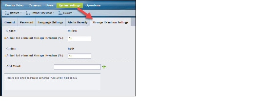
To determine when a warning is displayed in the Storage Retention Dashboard, enter the amount of deviation (as a percentage) between the actual and estimated storage for each video codec (Figure 7).
Email notifications can also be sent if this percentage is exceeded.
Figure 7 Storage Retention Settings
Step 1 Log in to the Cisco VSM Operations Manager.
Step 2 Choose System Settings > Settings.
Step 3 Click Storage Retention Settings.
Step 4 Actual to Estimated Storage Deviation percentage (%)—Enter a percentage value for each supported codec (MULAW and H264). The dashboard will display a ‘Warning’ for cameras that deviate above or below the specified percentage.
Step 5 Add Email—Enter the email addresses where warnings should be sent if the deviation between the actual and estimated storage exceeds the defined percentage.
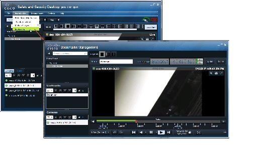
Mark and Search Video Streams Using Cisco SASD
This feature, called Bookmarks in Cisco SASD, allows an operator to mark live and recorded video streams whenever an event or incident happens. You can create these bookmarks for either a location or a particular camera. Operators can mark the events for something they may have spotted or viewed as important.
The users can search the bookmarks by providing the names or browse through bookmarks by location and view the event again without the need for creating a clip. These bookmarks, can be viewed by any user with “view recording” permissions; which makes it easy to share.
For example, if a security gets a call that a purse was lost in a store, or a car was damaged in a parking lot, they can quickly create a bookmark for an approximate time and date that is tied to the general location (all cameras at that location, or to a specific camera.
Cisco SASD bookmarks allow an operator to manually mark important events in the real time video stream.
Note The Cisco SASD Advanced Video Player, SASD Federator, and Cisco SASD Wall Configurator do not support this feature.
Create a Bookmark
Step 1 Launch the Cisco SASD application and log in.
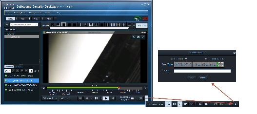
Step 2 Select the Video workspace (Figure 8).
Step 3 While viewing video, click
and then
.
Step 4 In the Add Bookmark window, the current camera is selected by default.
a. (Optional) Select a location instead, if necessary, to create a bookmark for all cameras in that location.
b. (Optional) Adjust the start date and time, if necessary.
Step 5 Enter the bookmark name.
Open a Bookmark
Step 1 Launch the Cisco SASD application and log in.
Step 2 Select Investigation > Bookmarks menu (Figure 9).
Step 3 Select a location to view all of the bookmarks in that location, or enter a name in the Search bookmarks field.
Step 4 Select a bookmark to display the cameras associated with the bookmark.
Step 5 Double-click a camera to see the bookmarked video for that device.
Step 6 (Optional) Use the following additional options:
a. Name—Change the bookmark name.
b. Timestamp—Change the bookmark start time.
c. Click Update to save the settings.
d. Click Delete to delete the bookmark.
Step 7 Use the additional playback controls to create clips or view the video.
Support for Cisco and Vivotek Cameras, and Axis Encoder
The following cameras and encoders are supported in this release. See the Supported Devices for more information.
Exclude Padding from On-Demand Recordings
Beginning with Release 7.9.1, administrators can specify if on-demand recordings in Cisco SASD excludes additional time (padding) before and after the selected recording time.
For example, when padding is enabled, additional recording is added before and after the user click start and stop. If padding is disabled, only the recording time selected by the user is included.
Step 1 Log in to the Cisco VSM Operations Manager.
Step 2 Edit or add a template to enable or disable padding:
a. Select Cameras > Templates.
b. Click Add to create a new template or select a location and template name.
Note System defined templates are locked and cannot be modified.
c. Click the Streaming, Recording and Events tab.
d. Next to On-Demand Recording, select Enable.
e. Check or uncheck Disable Padding.
f. Click Create , Save or Save As .
g. Wait for the Job to complete.
Step 3 Add cameras to the template if necessary.
c. Select Streaming, Recording and Events.
d. Click Set Template and select the template where padding is disabled, if necessary.
Tip: You can also click Custom to create a custom template for a single camera.e. Click Save to save the camera settings.
Step 4 When Cisco SASD users select on-demand recording, the recording will include or exclude additional video based on the camera settings.
Support for Additional Axis Cameras and Encoders
The following cameras and encoders are supported in this release.
See the Table 13 and Table 14 in Supported Devices: Axis for more information.
Support for JRE 1.8
Release 7.10 includes Java Runtime Environment (JRE) 1.8 to address security vulnerabilities in previous JRE releases.
Get Custom Resolution API
The getThumbnails Operations Manager API includes a new customResolution option to extract a thumbnail image with a specified resolution.
– True if snapshot is to be fetched from recorded stream.
– False if snapshot is to be fetched from Live stream.
- startTimeInMSec—Start Time of image.
- endTimeInMsed—End time of image.
- encoding—"base64" - currently only base64 encoding is supported.
- Recording Cataogue Entry—This field is specific to recording stream for cameras.
- resolution—resolution of the output JPEG image
– full—Full resolution of the image will be returned in the output. e.g. If the camera Stream is configured with a resolution of 1280 x 720, the resolution of the output image will be 1280 x 720
– half—Half resolution image will be returned in the output. e.g. If the camera Stream is configured with a resolution of 1280 x 720, the resolution of the output image will be 640 x 360
– quarter—Quarter resolution image will be returned in the output. e.g. If the camera Stream is configured with a resolution of 1280 x 720, the resolution of the output image will be 320 x 180
Covert Cameras
If a user is monitoring a video stream in Cisco SASD or Operations Manager, and the stream is switched to covert mode, the message “Attempting to Reconnect” is displayed (previously, the view would switch to the next available stream).
If a user is monitoring recorded video in Cisco SASD or Operations Manager, and the stream switched to covert or un-covert mode, the video will switch to the live video stream. If a user tries to reload the recording stream, however, the message “Failed to load Camera feed. Error message 401 Unauthorized” is displayed.
Supported SSL cipher algorithms
The following SSL cipher algorithms are supported. Contact your Cisco support representative for assistance to modify the cipher options, if necessary.
Tip By default, Cisco VSM supports all algorithms except RC4 and MD5. Learn more about the need for strong algorithms.
Android and iOS Limitations
The following limitations apply after enabling strong ciphers on Android or Apple iOS.
Windows 7 Limitations
The following Cisco VSM Operations Manager features do not work when strong ciphers are enabled on Windows 7.
- Clip creation.
- Pan, tilt, and zoom (PTZ) actions on the Monitor Video page and in a camera’s Image > PTZ tab.
- Motion window configuration. You can set the motion window but cannot view the configured motion window.
- Photographic controls.
Note Basic streaming capabilities such as viewing live or recorded videos and snapshots continue to work.
Other Improvements
- Maps uses OpenStreetMap by default for new installations. For existing upgrades from previous releases, you must manually change the default map provider.
- Security and performance enhancements.
- In Operations > Reports, added new reports for All Users and Templates reports.
- The 32 bit ActiveX client is depreciated after Release 7.10. The 64-bit client will be used for future releases. See Enabling 64-Bit Video Monitoring using Internet Explorer (IE) for more information.
- The Operations Manager works as a Single Page Application (SPA) on supported browsers for faster UI rendering. Supported Browsers are Internet Explorer 10 and higher, Chrome, Firefox, Edge & Safari 10 and higher.
- Cameras can be added in Cisco SASD from different locations into a Wall without losing changes, and then publish the modified View to the Wall.
Getting Started
Cisco VSM Release 7.10 is pre-installed on new servers, can be installed as a virtual machine, or used to upgrade an existing deployment.
Release 7.10 is pre-installed in new installations on the Cisco Connected Safety and Security UCS Platform Series servers:
See Cisco Connected Safety and Security UCS Platform Series Servers for more information.
Upgrades can be performed on Cisco VSM virtual machines (VMs) and on Cisco Video Surveillance servers.
Upgrade to 7.8 or 7.9 first, and then upgrade to the latest release.
See the Cisco Video Surveillance Manager: Install and Upgrade Guide.
An .OVA template file is used to install a new virtual machine (VM) instance of the server.
After an .OVA virtual machine is installed, you can use the Cisco VSM Management Console to perform future upgrades of the system software.
See Cisco Video Surveillance Virtual Machine Deployment and Recovery Guide for UCS Platforms for more information.
See the following for more information:
- Cisco Video Surveillance Manager: Install and Upgrade Guide
- Cisco Connected Safety and Security UCS Platform Series Servers
- Upgrading from Previous Cisco VSM Releases
- Recovery/Factory Image
Cisco Connected Safety and Security UCS Platform Series Servers
Cisco VSM Release 7.10 is pre-installed on new installations of the Cisco Connected Safety and Security UCS Platform Series when ordered with the Cisco VSM software installed.
- Cisco CSS UCS Server User Guide — supported features, physical installation and setup instructions
- Release Notes for the Cisco CSS UCS Servers
- After the server appliance is installed, see the Cisco Video Surveillance Manager: Install and Upgrade Guide to perform the initial Cisco VSM setup.
- For additional server hardware documentation, see the Cisco UCS C-Series Server Documentation (Roadmap) .
Upgrading from Previous Cisco VSM Releases
Cisco VSM can be upgraded using a
.zipupgrade file that includes all required software packages. Installing the.zipfile upgrades all components and ensures that all packages are running the required versions.For complete instructions, see the Cisco Video Surveillance Manager: Install and Upgrade Guide .
The following table describes the upgrade methods based on how old your server’s current release is.
- Use the Software Management page on the browser-based Operations Manager to upgrade all of the servers in your deployment.
- Clear the cache in each user’s web browser after upgrading Cisco VSM. If not cleared, the browser may attempt to use outdated content and display the error message “Operation failed: Authentication failed, this request is not allowed” until the page is refreshed.
- Always upgrade using the Cisco VSM user-interface. Do not perform the upgrade using the Linux CLI.
Recovery/Factory Image
You can also create a bootable USB flash drive that can be used to recover an installation or perform a a factory installation of Cisco VSM Release 7.10 on a supported physical server that shipped with Cisco VSM Release 7.10 pre-installed. This includes CPS-UCSM4-1RU-K9 and Cisco CPS UCSM4 2RU.
Released Versions
Cisco VSM Release 7.10 is released with 7.10 – 205i. The component package versions are:
- Cisco_Tomcat-7.0.55-3.el6.noarch
- Cisco_MetaDataService-7.10.0-090d.i686
- Cisco_VSTools-7.10.0-090d.i686
- Cisco_GeoServer-7.8.0-1.noarch
- Cisco_VSMUpgrade-7.10.0-090d.i686
- Cisco_AMQBroker-7.10.0-1.noarch
- Cisco_VSRecorder-7.10.0-090d.i686
- Cisco_VSDrivers-7.10.0-090d.i686
- Cisco_MPClient-7.10.0-68.noarch
- Cisco_DashCast-7.10.0-090d.i686
- Cisco_CDAF-7.10.0-176.noarch
- Cisco_VSF-7.10.0-176.noarch
- Cisco_VSBase-7.10.0-090d.i686
- Cisco_VSMS-7.10.0-090d.i686
- Cisco_SASD-7.10.0-94.noarch
- Cisco_VSOM-7.10.0-176.x86_64
Updated Firmware version for supported devices: v2.9.1-2.
The following Cisco IP cameras models support this firmware version:
Supported Devices
The following sections provide information about the devices that this version of Cisco VSM supports:
- Supported Devices: Cisco
- Supported Devices: Arecont
- Supported Devices: Axis
- Supported Devices: IQinVision
- Supported Devices: Mobotix
- Supported Devices: Panasonic
- Supported Devices: Pelco
- Supported Devices: Sony
- Supported Devices: Vivotek
- Supported Devices: Generic IP Cameras
- Supported Devices: Analog Cameras
- Device Models Validated in Cisco VSM as Generic IP Cameras
Supported Devices: Cisco
Table 5 through Table 11 provide information about Cisco devices supported in this release:
- Cisco 2400/2500, 2600, 2800, and 2900 Series
- Cisco 3000 Series
- Cisco 4000 Series and 5000 Series
- Cisco 6000 Series
- Cisco 7000 Series
- Cisco 8000 Series
- Cisco CIVS-SENC-4P and CIVS-SENC-8P
Additional Notes on Cisco Devices
- Cisco 4500 and 4500E support video analytics.
- Redundancy is supported for all Cisco devices some exceptions for the 2400, 2500, 2900 and 5000 series. The 2400, 2500, 2900 and 5000 series do not support sending events to the redundant server such motion detection and contact closure events.
- Cisco 5000 series does not support motion detection at video bit-rates above 4,000 (4 Mbps). The “H” video preset in Templates has been chosen to not exceed this, so motion detection will work.
- The Cisco 5000 and 2900 camera series do not allow changes to the authentication settings (username/password) or networking settings (DHCP/Static, DNS, etc.) through Cisco VSM. These values can only be changed using the camera web interfaces.
- Focus, Auto Focus and Zoom support are not available for Cisco 6000P, 3421V, 3520, 3530, 3535, and 3050 camera models.
- When Cisco VSM manages a Cisco 6930, 2830, or 2835 camera, it automatically enables the HTTP protocol on the camera and uses this protocol to send PTZ commands to the camera. Other configuration commands continue to use the HTTPS protocol.
- The Cisco 2830, 2835, 3000 series, 6000 series and 7030 cameras now support MJPEG primary streams.
- Cisco 3421V and 6050 cameras do not support Contact Closure, Cisco 7030 camera supports 3 input ports. All other Cisco 3000, 6000, 8000 series cameras support 1 input port.
- In PTZ Tour Configuration, the configured transition time configured includes the time that it takes the camera to move from the one preset position to the next preset position in addition to the time that the camera is expected to stay in the preset position. If the transition time is configured to a value that is less than the time that it takes the camera to move from one preset position to the next, the camera moves between the first and second presets positions only, instead of touring between all preset positions that are configured in the tour.
- The minimum firmware version required to support camera applications is 2.5.0-10.
- The minimum firmware version required to support connected edge storage is 2.0.
Supported Devices: Arecont
Table 12 provides information about Arecont devices that this Cisco VSM release supports.
Additional Notes on Arecont Devices
- AV20185, AV20365, AV12186, AV8365 and AV8185 are 4-channel IP cameras. In order to support multiple video channels from a single device, Cisco VSM 7 models these devices as “Encoders”.
- Arecont devices have not yet been qualified to support redundancy in Cisco VSM 7.
- Secondary streams are not supported in H, M, L template settings for Arecont Devices. However secondary stream can be configured using Custom templates.
- Arecont cameras divide the Maximum FPS the camera supports by the number of streams. This could result in lower FPS when both primary and secondary streams are configured for these cameras.
- Arecont AV10XX5, AV5115, AV2115 support VBR and multicast streaming.
- There is a restriction with motion detection for Arecont multi-sensor cameras. False motion events are generated if both half and full resolution size images are requested simultaneously using Cisco VSM or Arecont Camera Web Interface or a third party Media Player.
Supported Devices: Axis
Table 13 , Table 14 , and Table 15 provide information about Axis devices supported in this release.
Table 15 provides information about additional Axis devices that this Cisco VSM release supports.
Additional Notes on Axis Devices
- Axis P3301 IP camera and Q7401, Q7404, and Q7406 encoders have been qualified to support redundancy in Cisco VSM 7.0.1.
- Axis 233D supports contact closure configuration and events.
- Support for 0.1fps MJPEG stream for all supported Axis models.
The following table documents the various Field-Of-Views supported for the Axis M3007 panoramic cameras and support for PTZ and Motion Detection for these Field-Of-Views.
The Axis M3007 camera allows the user to configure various mounting options directly in the camera web interface that affects the possible values for Field-Of-Views that can be configured on the camera. The table below provides this mapping:
Supported Devices: IQinVision
Table 18 provides information about IQinVision devices that this Cisco VSM release supports.
Supported Devices: Mobotix
Table 19 provides information about Mobotix devices that this Cisco VSM release supports.
Supported Devices: Panasonic
Table 20 provides information about Panasonic devices that this Cisco VSM release supports.
Additional Notes on Panasonic Devices
- Panasonic devices have not yet been qualified to support redundancy in Cisco VSM 7.
- Only same field of views can be configured on primary and secondary streams on Panasonic cameras SW458/SF438.
- The following table documents the various Field-Of-Views supported for the Panasonic SF 458 and SF 438 panoramic cameras and support for PTZ and Motion Detection for these Field-Of-Views.
Supported Devices: Pelco
Table 22 provides information about Pelco devices that this release supports.
Additional Notes on Pelco Devices
- Pelco devices have not yet been qualified to support Redundancy in Cisco VSM 7.
- Audio volume controls are not supported for NET540XT
- For Pelco NET540xT PTZ to work, the analog camera should be chosen as Pelco Analog Camera (pelco_sarix) in Operations Manager and not as Pelco D.
- The user needs to directly configure the Serial protocol on the Pelco NET540XT encoder outside of Cisco VSM.
- The Pelco Spectra IV TXB-N (H.264 capable model) run Pelco Sarix firmware and can be supported in Cisco VSM as a Pelco Sarix Generic IP camera (additional details in the Generic IP camera section).
Supported Devices: Sony
Table 23 provides information about Sony devices that this release supports.
Additional Notes on Sony Devices
- Sony devices have not yet been qualified to support redundancy in Cisco VSM 7.
- These Sony devices do not support motion detection with the H.264 media type.
- The Sony SNC-RX5x0 cameras stop streaming video when the Object Detection window is opened in the camera’s web interface.
- For Sony HM662 Panoramic camera, only the 360 degree view is supported. De-warped views are not supported.
Supported Devices: Vivotek
Table 24 provides information about Vivotek devices that this release supports.
Supported Devices: Generic IP Cameras
Cisco VSM Release 7.10 provides the following device drivers to support IP cameras from various vendors. The functionality they support will depend on the particular device that they are used with. They are intended to provide a quick and easy way to support devices for which there isn’t yet a specific driver available for Cisco VSM. Since these drivers may not be tested with a specific device, some issues may be encountered. When using these drivers with a device, failover and redundancy are not supported.
Note The vendor specific generic driver should always be used before a non-vendor specific driver such as ONVIF.
- Supports only IP Cameras, no support for Encoders
- No contact closure support
- Multicast streaming is supported only for the primary stream
- Multicast port must be an even number within the range 16000:19999
- Audio Multicast issues are observed on most of the ONVIF cameras. Hence do not enable audio when multicast is enabled for video.
- Capture Mode on the camera cannot be changed using ONVIF APIs. So, it is assumed that the camera is in the desired capture mode before adding it to VSOM using ONVIF
- This ONVIF driver has been tested with a limited number of camera models from Axis, Sony, Panasonic, Bosch, Pelco, Samsung, J2000IP, Hikvision and Cohu. We have found that these cameras have some variations in how they have implemented the ONVIF specification. Hence there may be compatibility issues when using this ONVIF driver with a particular device that is ONVIF compliant.
- Some of the known caveats are listed below:
- ONVIF user account—Some Axis cameras require a special ONVIF user account, which can be created on the camera's web interface before adding an AXIS ONVIF camera to the VSOM. This page is at Setup --> System Options --> Security --> ONVIF --> Add
- Camera and VSMS (Media Server) Time Synchronization—ONVIF camera and VSMS server to which ONVIF camera is being added should have their time synchronized ideally using NTP.
- Codec Change through VSOM—Hikvision camera requires a reboot after the codec is changed from VSOM.
- The Minimum Firmware Version of Hikvision cameras supported is V5.3.0, to be added as ONVIF camera in Cisco VSM.
- Megapixel Mode setting on the camera SND-7080
- To support the resolutions (1600*1200) and (2048*1536), change the Megapixel Mode to 3-Megapixel in the following page on the camera browser: Settings -> Audio & Video -> video profile -> Megapixel mode
- Enable Authentication on the camera before adding it to VSOM In the camera browser, go to Camera Setup -> Configuration -> User Settings. Select User and enable “Require Password” field.
- Media Transport Type— Only UDP is supported. Streaming fails if TCP is selected.
- Unsupported Resolutions —Streaming fails for the resolutions 176*144, 176*120, 160*120
- Codec Change through VSOM— Switching from H264 to JPEG or vice-versa requires a camera reboot. And camera needs to be deleted and added in VSOM after camera is up.
- Support for Audio— Camera does not support ONVIF Audio
- Frame rate— Only Framerate 30 is supported
- Dual Streaming— Secondary configuration overwrites the primary configuration. So, dual streaming is not supported on Bosch cameras using ONVIF.
- Capture Mode Setting— If the camera is added in VSOM using Multicast, changing the capture mode on the camera browser manually causes the streaming to fail. After this, only the unicast streaming works
- User Authentication— User Authentication should be enabled in the camera browser as follows - Setup -> User mng -> User auth. Choose ON for User auth.
- Media Transport Type— Only UDP is supported. Streaming fails if TCP is selected
- Support for Audio— Camera does not support ONVIF Audio
- Set Configuration Issues — Camera returns success even if one or more of the parameters are not valid for that camera/video stream. ONVIF profile gets updated with values but Camera still uses the previous correct value. Recommend to configure only the values as allowed in the camera browser.
- Support for Password change on the camera— Camera does not support password change for the administrator users using ONVIF API.
Supported Devices: Analog Cameras
This Cisco VSM release provides support for the following analog cameras.
Device Models Validated in Cisco VSM as Generic IP Cameras
The camera models listed in Table 27 have been tested with VSM Release 7.10 as generic IP cameras.
Clipping Support By Application
You can create and view video clips using the following Cisco VSM applications:
Note When converting a virtual clip to an MP4 file, only the entire duration of the virtual clip can be saved, not a segment.
Obtaining and Installing Licenses
To install a license, purchase the license and obtain the license file, then upload the file to the Operations Manager.
Table 29 lists the part numbers for the Cisco VSM licenses. Multiple camera and VSMS licenses can be included in a single license file. For example, a single license file might include support for 25 additional cameras and two additional VSMS devices.
- A license for 10,000 Cisco cameras is included by default (you do not need to purchase and install an additional license for Cisco cameras).
- You can add 1 Media Server and 10 non-Cisco cameras without a license for initial setup purposes only. This feature is removed when you add any permanent license.
Step 1 Purchase additional licenses:
a. Determine the part number for the license you want to purchase (see Table 29 ).
b. Purchase the license by contacting your Cisco sales representative or any Cisco reseller. For more information, visit http://www.cisco.com/en/US/ordering/index.shtml .
c. When the purchase is complete, you are issued a Product Authorization Key (PAK) in paper form, or in an e-mail message.
Step 2 Obtain the license file:
a. Locate the Product Authorization Key (PAK) that was created with the purchase.
b. In a web browser, open the Cisco Product License Registration web page.
http://www.cisco.com/go/license/
c. Follow the on-screen instructions to complete the form and enter the Product Authorization Key (PAK). When you are done, a license file with the extension
.licis sent to your e-mail address.d. Transfer the file to the drive of the PC used for the configuration.
Step 3 Install the license file in Cisco VSM:
a. Log in to the Operations Manager.
b. Select System Settings > Software Licensing .
c. Click Add and select the license file located on your local drive.
d. Click Save to install the file and activate the additional capacity.
The additional capacity is available immediately. You do not need to restart the server or take additional steps.
See the Cisco Video Surveillance Operations Manager User Guide for more information.
Understanding the Cisco VSM Software Types
Table 30 describes the different types of software and firmware that are installed on servers, cameras, and encoders.
System software denotes the Cisco VSM software, including Media Server, Operations Manager, Cisco VSM Management Console, Safety and Security Desktop and Multipane clients. All servers running the Operations Manager and associated Media Server services must run the same software version.
Use the Operations Manager to update the System Software on all servers (such as Media Servers) associated with the Operations Manager. See the Cisco Video Surveillance Operations Manager User Guide for instructions.
- The Operations Manager and all associated servers must run the same system software version.
- To update a Federator server, log in to the Federator server Management Console. See the Cisco Video Surveillance Operations Manager User Guide for instructions.
- To repair or restore the Cisco VSM system software, see the Cisco Video Surveillance Manager: Install and Upgrade Guide for your hardware platform. For VM installations, see the Cisco Video Surveillance Virtual Machine Deployment and Recovery Guide for UCS Platforms ).
OVF template files are used to install the system software as a virtual machine (VM) on a supported Cisco Unified Computing System (UCS) platform.
- OVA template files are downloaded from the Cisco website.
- The file format is
.ova.For example:Cisco_VSM-7.10-331d_ucs-bc.ova- See the Cisco Video Surveillance Virtual Machine Deployment and Recovery Guide for UCS Platforms for instructions to install the .ova image and perform the initial VM setup.
- After the VM setup is complete, use the Management Console to complete the configuration.
Use the USB Recovery Disk image to create a Cisco VSM 7 Recovery Flash Drive (for example, on a USB stick). The recovery disk can be used do the following:
- Repair: reinstalls the Operating System files and partitions without erasing video files stored on the server. You must backup the Cisco VSM database before using the recovery image, and then restore the database after the recovery process is complete. This action also preserves the RAID configuration.
- Factory Restore: Restores the server to its factory default settings, reinstalls the operating system, and clears and reconfigures the RAID. This action deletes all data, configurations, software and video files from the appliance, and then reinstalls the operating system and Cisco VSM software. Perform this procedure only if necessary.
See the Cisco CSS UCS Server User Guide for more information.
Device firmware is provided by the device manufacturer. The firmware for Cisco devices can be upgraded using Operations Manager. Firmware for other manufacturers is upgraded using a direct connection.
See the “Upgrading Camera and Encoder Driver Firmware” section of the Cisco Video Surveillance Operations Manager User Guide for instructions to upgrade Cisco device firmware, or refer to the device documentation.
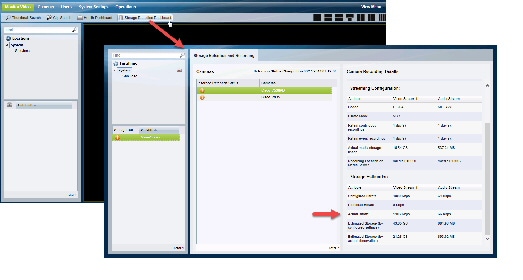
Device driver packs are the software packages used by Media Servers and the Operations Manager to interoperate with video devices, such as cameras. Driver packs are included with the Cisco VSM software, or may be added to a server at a later time to add support for new devices or features.
- Install new driver packs to add support for additional devices.
- Upgrade existing driver packs to enable support for new features.
- When updating or installing a driver pack, you first install the file on the Operations Manager, and then on the Media Servers that support the cameras or encoders. You can install the new version on all Media Servers, or only the Media Server(s) that support the affected devices. If the driver pack version is different on the Media Servers in your deployment, a driver pack mismatch error can occur.
– A warning message is informational only and the cameras and encoders can be configured normally.
– A critical message appears if the driver pack mismatch will impact the functionality or compatibility between the Operations Manager, Media Servers, and the video device. The upgrade is not allowed. Camera and encoder templates cannot be revised until the same driver pack version is installed on all Media Servers.
Note We strongly recommend upgrading driver packs using the Operations Manager interface (see the “Driver Pack Management” section of the Cisco Video Surveillance Operations Manager User Guide). This allows you to upgrade multiple servers at once.
Language packs can be added to display the Cisco VSM user interfaces in non-English languages.
Language packs are added using the Operations Manager (release 7.6 and higher). See the Cisco Video Surveillance Operations Manager User Guide for instructions.
Obtaining Cisco VSM Software
Complete the following procedure to obtain software and other information for the Cisco VSM products and components:
Step 1 Go to the Cisco Video Surveillance Manager product page .
Step 2 Click Download Software .
Step 3 Select a product category. For example:
- Video Surveillance Device Driver
- Video Surveillance Manager Stand-alone Tools
- Video Surveillance Media Server Software (including system software)
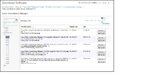
Step 4 Select the release for your server, device, or deployment (Figure 10).
Step 5 Click Download or Add to Cart and follow the onscreen instructions.
Figure 10 Download Software Page
You can also navigate the Cisco Physical Security product pages to download software updates and other information:
Step 1 Go to the following URL.
http://www.cisco.com/go/physicalsecurity
Step 2 Click View All Physical Security Products.
Step 3 Click IP Video Surveillance.
Step 4 Click Cisco Video Surveillance Manager.
Step 5 Click Download Software for this Product .
Step 6 Click a Software Type and follow the onscreen instructions.
For example: Video Surveillance Media Server Software (Figure 10).
Step 7 Select the release for your server, device, or deployment.
Step 8 Click Download or Add to Cart and follow the onscreen instructions.
Caveats
This section includes the following topics:
Using the Software Bug Search Tool
You can use the Bug Search Tool to find information about most caveats for Cisco VSM releases, including a description of the problems and available workarounds. The Bug Search Tool lists both open and resolved caveats.
To access Bug Search Tool, you need the following items:
To use the Software Bug Search Tool, follow these steps:
Step 1 To access the Bug Search Tool, go to https://tools.cisco.com/bugsearch/
Step 2 Log in with your Cisco.com user ID and password.
Step 3 To look for information about a specific problem, enter the bug ID number in the Search for field.
Step 4 For more information, go to the Bug Search interactive tour .
Open Caveats
Table 31 lists caveats that are open in this release.
Resolved Caveats
Table 32 lists caveats that are resolved in this release.
Related Documentation
See the following locations for the most current information and documentation:
Cisco Video Surveillance 7 Documentation Roadmap
Descriptions and links to Cisco Video Surveillance documentation, server and storage platform documentation, and other related documentation.
http://www.cisco.com/go/physicalsecurity/vsm/roadmap
Cisco Physical Security Product Information:
www.cisco.com/go/physicalsecurity/
Cisco Video Surveillance Manager Documentation Website
www.cisco.com/go/physicalsecurity/vsm/docs
Cisco and the Cisco logo are trademarks or registered trademarks of Cisco and/or its affiliates in the U.S. and other countries. To view a list of Cisco trademarks, go to this URL: www.cisco.com/go/trademarks . Third-party trademarks mentioned are the property of their respective owners. The use of the word partner does not imply a partnership relationship between Cisco and any other company. (1721R)
Any Internet Protocol (IP) addresses and phone numbers used in this document are not intended to be actual addresses and phone numbers. Any examples, command display output, network topology diagrams, and other figures included in the document are shown for illustrative purposes only. Any use of actual IP addresses or phone numbers in illustrative content is unintentional and coincidental.
 icon (or press
  icon to remove an email address.
 Feedback
Contact Cisco
- Open a Support Case

- (Requires a Cisco Service Contract)