Cisco Video Surveillance PTZ IP Camera Installation Guide
Bias-Free Language
The documentation set for this product strives to use bias-free language. For the purposes of this documentation set, bias-free is defined as language that does not imply discrimination based on age, disability, gender, racial identity, ethnic identity, sexual orientation, socioeconomic status, and intersectionality. Exceptions may be present in the documentation due to language that is hardcoded in the user interfaces of the product software, language used based on RFP documentation, or language that is used by a referenced third-party product. Learn more about how Cisco is using Inclusive Language.
- Updated:
- May 20, 2013
Chapter: Overview
Overview
This chapter describes the Cisco Video Surveillance pan, tilt, and zoom (PTZ) IP cameras, and includes the following topics:
•![]() PTZ IP Camera Physical Details
PTZ IP Camera Physical Details
Introduction
The Cisco Video Surveillance PTZ IP cameras are primarily used for monitoring wide open outdoor areas such as building entrances, airports, highways, and parking lots.
The dome cover protects the camera body against rain and dust. The wide temperature range allows the camera to operate under extreme weather conditions.
The following PTZ IP cameras are available:
•![]() Cisco Video Surveillance SD Outdoor 2830 PTZ IP Camera, NTSC
Cisco Video Surveillance SD Outdoor 2830 PTZ IP Camera, NTSC
•![]() Cisco Video Surveillance SD Outdoor 2835 PTZ IP Camera, PAL
Cisco Video Surveillance SD Outdoor 2835 PTZ IP Camera, PAL
•![]() Cisco Video Surveillance HD Outdoor 6930 PTZ IP Camera
Cisco Video Surveillance HD Outdoor 6930 PTZ IP Camera
For installers, properly adjusting the focus of an HD IP camera can be difficult due to the image detail. To make installation and adjustment easier, the PTZ IP camera incorporates built-in stepping motors that the installer can use to remotely control the focal length and precisely adjust the camera focus.
For complete installation and tampering prevention, the PTZ IP camera also fits different conduits and corrugated tubes sizes for cable installation.
Package Contents
The Cisco Video Surveillance PTZ IP camera package includes the following items:
•![]() Cisco Video Surveillance PTZ IP Camera (1)
Cisco Video Surveillance PTZ IP Camera (1)
•![]() Pendant cap (1)
Pendant cap (1)
•![]() Screw driver (1)
Screw driver (1)
•![]() Ethernet cable (1)
Ethernet cable (1)
•![]() O-RING (1)
O-RING (1)
•![]() Ground wire (1)
Ground wire (1)
•![]() Waterproof connector (1)
Waterproof connector (1)
•![]() Connector (1)
Connector (1)
•![]() Terminal blocks (2)
Terminal blocks (2)
•![]() Silica gel packets (2)
Silica gel packets (2)
•![]() Twin adhesives (2)
Twin adhesives (2)
•![]() Screws M5x8 (3)
Screws M5x8 (3)
•![]() Screws M4x8 (3)
Screws M4x8 (3)
•![]() Screw M3x5 (1)
Screw M3x5 (1)
•![]() Extra set of product labels (3)
Extra set of product labels (3)
•![]() Cisco documentation pointer card (P/N: 78-21181-01)
Cisco documentation pointer card (P/N: 78-21181-01)
•![]() Cisco RoHS document (1)
Cisco RoHS document (1)
PTZ IP Camera Physical Details
Figure 1-1 and the table that follows describe the outer view of the PTZ IP camera.
Figure 1-1 Outer View of the PTZ IP Camera

Reset Button |
Recessed button that reboots the PTZ IP camera or resets it to a default state. You can use a pin or paper clip to depress it. Depending on how long you depress the reset button, you can do either of the following: • • |
Network LED |
Status of the network to which the camera is attached. |
Status LED |
Status of the PTZ IP camera. For more information, see Table 1-1. |
Lens |
Lens that pans, tilts and zooms. |
Figure 1-2 and the table that follows describe the inner view of the PTZ IP camera.
Figure 1-2 Inner View of the PTZ IP Camera

|
|
Board-to-board Connector |
Board to board connector. |
|
|
SD/SDHC/SDXC Card Slot |
Slot for the SD, SDHC, or SDXC card. |
Status LEDs
Table 1-1 describes the LED indicator for each PTZ IP camera status state.
Figure 1-3 shows the interface view of the PTZ IP camera.
Figure 1-3 Interface View
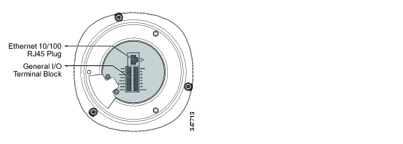
Ethernet 10/100 RJ45 Plug |
Plug for a standard LAN cable to connect the PTZ IP camera to a 10/100BaseT router or switch. |
General I/O Terminal Block |
General purpose input/output (GPIO) terminal block that is used to connect external input and output devices. For more information, see Table 1-2. |
Table 1-2 shows the order of the GPIO terminal block.
AC24V |
DI GND |
|
|---|---|---|
AC24V |
DI4 |
|
Reserved |
DI3 |
|
MIC IN |
DI2 |
|
Line OUT |
DI1 |
|
Audio GND |
DO2 |
|
RS485- |
DO1 |
|
RS485+ |
DO+(12V) |
 Feedback