Cisco Video Surveillance PTZ IP Camera Installation Guide
Bias-Free Language
The documentation set for this product strives to use bias-free language. For the purposes of this documentation set, bias-free is defined as language that does not imply discrimination based on age, disability, gender, racial identity, ethnic identity, sexual orientation, socioeconomic status, and intersectionality. Exceptions may be present in the documentation due to language that is hardcoded in the user interfaces of the product software, language used based on RFP documentation, or language that is used by a referenced third-party product. Learn more about how Cisco is using Inclusive Language.
- Updated:
- May 21, 2013
Chapter: Installing the Camera
Installing the Camera
This chapter provides information and instructions for installing the Cisco Video Surveillance PTZ IP camera, and includes the following topics:
The installation procedures apply to the following PTZ IP cameras:
•![]() Cisco Video Surveillance SD Outdoor PTZ IP Camera, NTSC (CIVS-IPC-2830)
Cisco Video Surveillance SD Outdoor PTZ IP Camera, NTSC (CIVS-IPC-2830)
•![]() Cisco Video Surveillance SD Outdoor PTZ IP Camera, PAL (CIVS-IPC-2835)
Cisco Video Surveillance SD Outdoor PTZ IP Camera, PAL (CIVS-IPC-2835)
•![]() Cisco Video Surveillance HD Outdoor PTZ IP Camera (CIVS-IPC-6930)
Cisco Video Surveillance HD Outdoor PTZ IP Camera (CIVS-IPC-6930)
Installation Guidelines
Before you begin the installation, review these guidelines:
•![]() The PTZ IP camera requires a network cable and a connection to a standard 10/100BaseT router or switch. To power the PTZ IP camera with Power over Ethernet (PoE), a switch must be 802.3af compliant.
The PTZ IP camera requires a network cable and a connection to a standard 10/100BaseT router or switch. To power the PTZ IP camera with Power over Ethernet (PoE), a switch must be 802.3af compliant.
•![]() If you are using the PTZ IP camera on a network connection that does not provide PoE, you must use a third-party AC 24V power adapter.
If you are using the PTZ IP camera on a network connection that does not provide PoE, you must use a third-party AC 24V power adapter.
•![]() If you are using an external speaker, microphone, input device, output device, or pan/tilt control device, you must configure additional settings after installing and performing the initial set up of the PTZ IP camera before the external device can fully operate. For detailed information about these settings, see the Cisco Video Surveillance PTZ IP Camera Configuration Guide.
If you are using an external speaker, microphone, input device, output device, or pan/tilt control device, you must configure additional settings after installing and performing the initial set up of the PTZ IP camera before the external device can fully operate. For detailed information about these settings, see the Cisco Video Surveillance PTZ IP Camera Configuration Guide.
•![]() If you do not connect an external device (speaker, microphone, input, output, or pan/tilt control) when you perform the following installation procedure, you can install any of these devices later.
If you do not connect an external device (speaker, microphone, input, output, or pan/tilt control) when you perform the following installation procedure, you can install any of these devices later.
Warnings Before Installation
 |
Warning |
|
Warning |

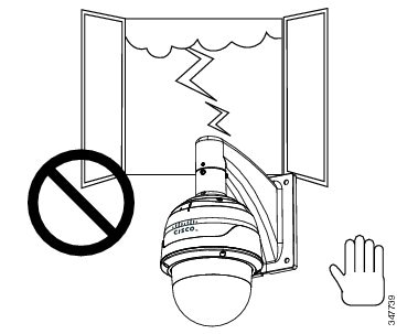
Note ![]() If you use the IP camera outdoors, place the camera and the power supply in a suitable NEMA enclosure.
If you use the IP camera outdoors, place the camera and the power supply in a suitable NEMA enclosure.
|
Warning |

Note ![]() The power adapter that you use with the IP camera must provide power that is within +/-10% of the required power.
The power adapter that you use with the IP camera must provide power that is within +/-10% of the required power.
Note ![]() The equipment is to be connected to a Listed class 2, limited power source.
The equipment is to be connected to a Listed class 2, limited power source.
Installing the PTZ IP Camera
Use the procedures in this section to install the PTZ IP camera.
Cabling Through Waterproof Connectors
Perform the following steps to install and connect an external power cable and I/O cables for external devices:
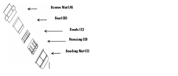
Step 1 ![]() Disassemble the components of the waterproof connector into parts (A)-(E).
Disassemble the components of the waterproof connector into parts (A)-(E).
Step 2 ![]() Remove the plastic stopper from the bottom of the dome cap and keep the M20 hex nut.
Remove the plastic stopper from the bottom of the dome cap and keep the M20 hex nut.
Step 3 ![]() Depending on the number of wires, remove seals (C) from the rubber seal (B).
Depending on the number of wires, remove seals (C) from the rubber seal (B).
Step 4 ![]() Feed the power cable through the waterproof connector (E --> D --> B --> A). Be sure to feed enough power cable length through the waterproof connector to connect the power cable to the GPIO block.
Feed the power cable through the waterproof connector (E --> D --> B --> A). Be sure to feed enough power cable length through the waterproof connector to connect the power cable to the GPIO block.
The recommended cable gauge is 1.2-1.8 mm.
Note ![]() There are 16 holes on the seal (B), and the widest holes with a crack on the side are specific for power cables.
There are 16 holes on the seal (B), and the widest holes with a crack on the side are specific for power cables.
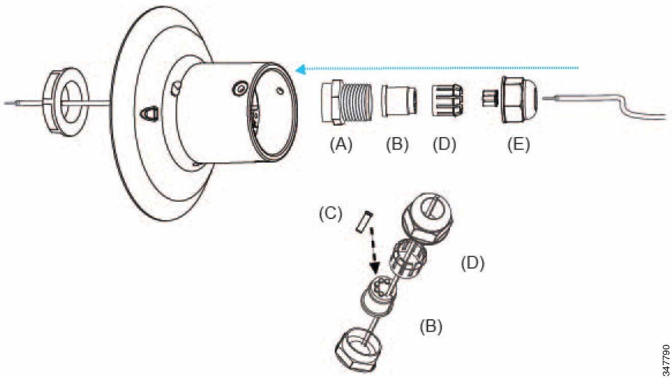
Step 5 ![]() Push the seal (B) into the housing (D).
Push the seal (B) into the housing (D).
Step 6 ![]() Insert the seals (C) into unused holes on the seal (B) to avoid moisture.
Insert the seals (C) into unused holes on the seal (B) to avoid moisture.
Step 7 ![]() Secure the sealing nut (E) and hex nut from the bottom of the camera tightly.
Secure the sealing nut (E) and hex nut from the bottom of the camera tightly.
Connecting the Cables
Perform the following steps to install and connect the I/O wires and RJ45 Ethernet cable.
Note ![]() We recommend using 24AWG (0.51 mm) gauge cable.
We recommend using 24AWG (0.51 mm) gauge cable.
Step 1 ![]() Use a small-size flat-blade screwdriver to secure I/O wires to the included terminal blocks.
Use a small-size flat-blade screwdriver to secure I/O wires to the included terminal blocks.
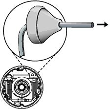
Step 2 ![]() Drill a hole on the rubber seal plug and insert an Ethernet cable (without a connector) through the opening.
Drill a hole on the rubber seal plug and insert an Ethernet cable (without a connector) through the opening.
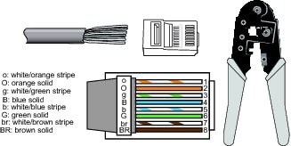
Step 3 ![]() Strip about 1/2 inch (12 mm) of the sheath from the Ethernet cable.
Strip about 1/2 inch (12 mm) of the sheath from the Ethernet cable.
Step 4 ![]() Use an RJ45 crimping tool to attach the Ethernet wires to a connector. When done, connect the cable to the camera's Ethernet RJ45 socket.
Use an RJ45 crimping tool to attach the Ethernet wires to a connector. When done, connect the cable to the camera's Ethernet RJ45 socket.
Step 5 ![]() Feed the Ethernet cable and I/O wires through the mounting bracket, the openings on the dome cap, and to the interface section. Attach the rubber seal plug to dome cap for water proofing.
Feed the Ethernet cable and I/O wires through the mounting bracket, the openings on the dome cap, and to the interface section. Attach the rubber seal plug to dome cap for water proofing.
Step 6 ![]() Secure the included ground wire to the dome cap, pass it through the mount bracket, and connect the other end to a grounded conduit later.
Secure the included ground wire to the dome cap, pass it through the mount bracket, and connect the other end to a grounded conduit later.
Preparing the Camera
Prior to mounting the camera to the wall or ceiling, attach the silica gel packets to the camera using these steps.
Step 1 ![]() Remove the black dome cover of the camera.
Remove the black dome cover of the camera.
Step 2 ![]() Turn the camera upside down.
Turn the camera upside down.
Step 3 ![]() Attach the silica gel packets to the inside wall of the camera using the adhesive strips.
Attach the silica gel packets to the inside wall of the camera using the adhesive strips.
Step 4 ![]() Attach the black cover to the camera.
Attach the black cover to the camera.
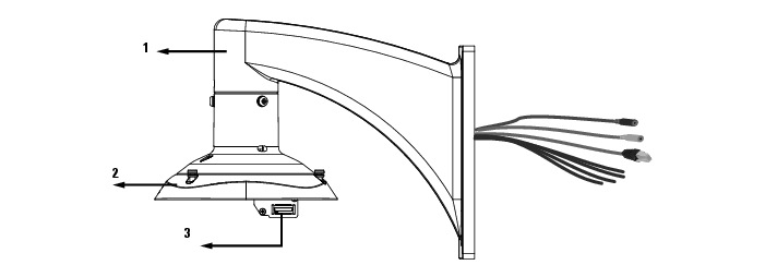
Mounting to the Wall
You can connect the PTZ IP camera to the wall using the following accessories:
•![]() Goose neck for wall mount—CIVS-6KA-GNECK=
Goose neck for wall mount—CIVS-6KA-GNECK=
•![]() Adaptor—CIVS-PA-PTZADPTR=
Adaptor—CIVS-PA-PTZADPTR=
Connecting to the Mount Bracket
Use these steps to connect cables to the mount bracket.
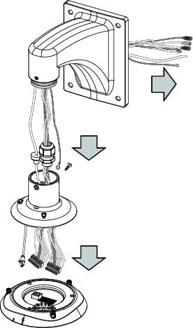
Step 1 ![]() Press the seal ring into the groove on canister.
Press the seal ring into the groove on canister.
Use the black machine screws (M4x8) to attach the interface section to the dome cap.
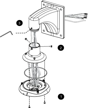
Step 2 ![]() Secure the dome cap to the mount bracket.
Secure the dome cap to the mount bracket.
Step 3 ![]() Use the included hex wrench to secure the connection.
Use the included hex wrench to secure the connection.
You can now carry the camera and the top section to the installation site.
|
|
Mount bracket |
|
|
Interface section |
|
|
Board-to-board connector |
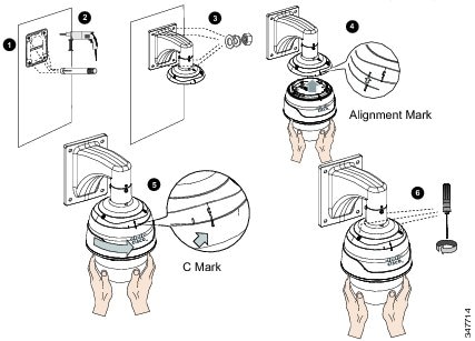
Mounting the PTZ Camera
Note ![]() Before mounting the camera, install an SD, SDHC, or SDXC card if you prefer recording to local storage.
Before mounting the camera, install an SD, SDHC, or SDXC card if you prefer recording to local storage.
Step 1 ![]() Select a rigid mounting location to prevent vibration to the camera, and attach the alignment sticker to the wall.
Select a rigid mounting location to prevent vibration to the camera, and attach the alignment sticker to the wall.
Note ![]() The camera weighs 3.66kg.
The camera weighs 3.66kg.
Step 2 ![]() Drill four pilot holes (10mm in diameter and 4cm deep) into the wall, and hammer in threaded anchors.
Drill four pilot holes (10mm in diameter and 4cm deep) into the wall, and hammer in threaded anchors.
Note ![]() Hammer the anchors with hex nuts on them, so the threaded poles do not get deformed. If preferred, drill another hole for routing cables.
Hammer the anchors with hex nuts on them, so the threaded poles do not get deformed. If preferred, drill another hole for routing cables.
Step 3 ![]() Secure the wall mount bracket to wall using four sets of captive washers and nuts.
Secure the wall mount bracket to wall using four sets of captive washers and nuts.
Step 4 ![]() Align the camera body with the top section.
Align the camera body with the top section.
a. ![]() Align the alignment mark on the camera with that on the interface section.
Align the alignment mark on the camera with that on the interface section.
b. ![]() Push the camera up to match the top section.
Push the camera up to match the top section.
Step 5 ![]() Rotate the camera clockwise until its alignment mark is aligned with the "C" mark.
Rotate the camera clockwise until its alignment mark is aligned with the "C" mark.
Step 6 ![]() Use the included T25 stardriver to securely tighten the three anti-tamper screws from the top.
Use the included T25 stardriver to securely tighten the three anti-tamper screws from the top.
Mounting to the Ceiling
You can connect the PTZ IP camera to the ceiling using the following accessories:
•![]() 20cm Pendent Pipe with Adaptor Installed—CIVS-PA-EXT=
20cm Pendent Pipe with Adaptor Installed—CIVS-PA-EXT=
•![]() Pendant Head—CIVS-6KA-PENHEAD=
Pendant Head—CIVS-6KA-PENHEAD=
Connecting to the Pendant Pipe
Use these steps to mount the camera to the ceiling using a pendant pipe.
Step 1 ![]() Determine a hard surface ceiling location, and use the alignment sticker to mark the positions where holes will be drilled to secure the pendant head.
Determine a hard surface ceiling location, and use the alignment sticker to mark the positions where holes will be drilled to secure the pendant head.
Hammer the anchors into the ceiling.
Note ![]() Mounting holes should be 10 mm in diameter and 60 mm deep. Use M6.2 x75mm screws.
Mounting holes should be 10 mm in diameter and 60 mm deep. Use M6.2 x75mm screws.

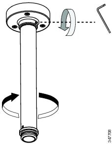
Step 2 ![]() Attach the pendant pipe to the pendant head by turning the pipe clockwise.
Attach the pendant pipe to the pendant head by turning the pipe clockwise.
Step 3 ![]() Secure the connection using a 3mm hex wrench.
Secure the connection using a 3mm hex wrench.
Step 4 ![]() Route power lines and other wires through the pendant head. You may apply a 1 inch conduit.
Route power lines and other wires through the pendant head. You may apply a 1 inch conduit.
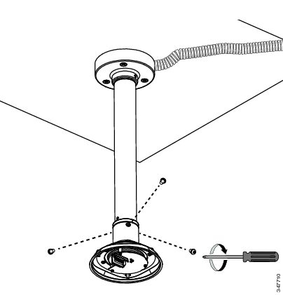
Step 5 ![]() Secure the pendant head to the ceiling by using the M6.2 x75mm screws.
Secure the pendant head to the ceiling by using the M6.2 x75mm screws.
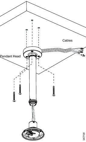
Step 6 ![]() Secure the camera's top section to the pendant head by fastening 3 M5x8 screws.
Secure the camera's top section to the pendant head by fastening 3 M5x8 screws.
Step 7 ![]() Attach the camera using Step 4-Step 6 in the Mounting the PTZ Camera section.
Attach the camera using Step 4-Step 6 in the Mounting the PTZ Camera section.
Connecting to the Network
Use the following steps to connect the camera to a Power over Ethernet (PoE) switch:
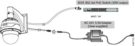
Step 1 ![]() Connect the camera's Ethernet cable (CAT5e or better) to a PoE Plus switch.
Connect the camera's Ethernet cable (CAT5e or better) to a PoE Plus switch.
A30W PoE output port alone cannot drive the onboard heater. If using the PoE switch, the application does not apply in low-temperature condition. A 30W PoE plus can only drive the camera when it is working at a temperature higher than -10ºC.
Step 2 ![]() Connect the power wires to an AC 24V power adaptor (user-supplied).
Connect the power wires to an AC 24V power adaptor (user-supplied).
The AC 24V adapter can drive the camera and the onboard heater. You can connect both power sources for redundancy in power supply.
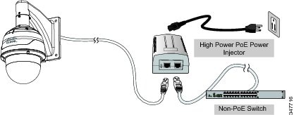
If you are using a non-PoE switch, use a high power PoE power injector with a 60W output to connect between the camera and non-PoE switch.
Sufficient power is required for low temperature conditions when the onboard heater is activated.
What to do next
•![]() After you install the PTZ IP camera, follow the instructions in the "Performing the Initial Setup of the IP Camera" section to access the camera through your network.
After you install the PTZ IP camera, follow the instructions in the "Performing the Initial Setup of the IP Camera" section to access the camera through your network.
•![]() After completing the initial setup, use the PTZ IP camera user interface in the Managing the Camera section to adjust the focal length and zoom factor.
After completing the initial setup, use the PTZ IP camera user interface in the Managing the Camera section to adjust the focal length and zoom factor.
For complete configuration information, refer to the Cisco Video Surveillance PTZ IP Configuration Guide.
 Feedback