Camera Installation
This chapter provides information and instructions for installing the Cisco Video Surveillance 3421V IP Camera, and includes the following topics:
Installation Guidelines
This section describes how to install the IP camera. Before installing, review these guidelines:
- The IP camera requires a network cable and a connection to a standard 10/100BaseT router or switch. To power the IP camera with Power over Ethernet (PoE), a switch must be 802.3af compliant.
- If you are using the IP camera on a network connection that does not provide PoE, you must use a Cisco 12 VDC power adapter (Cisco part number CIVS-PWRPAC-12V).
- If you are using an external input device, you must configure additional settings after installing and performing the initial set up of the IP camera before the external device can fully operate. For detailed information about these settings, see the Cisco Video Surveillance 3000 Series IP Camera Configuration Guide.
- If you do not connect an external input device when you perform the following installation procedure, you can install it later.
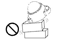
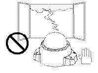
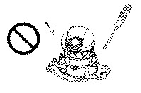
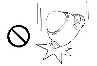
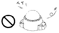
Warnings Before Installation
|
|
|
|
|
|
|
|
|

Warning![]() Installation of the equipment must comply with local and national electrical codes. Statement 1074
Installation of the equipment must comply with local and national electrical codes. Statement 1074
Warning![]() The power supply must be placed indoors. Statement 331
The power supply must be placed indoors. Statement 331
Warning![]() This product must be connected to a power-over-ethernet (PoE) IEEE 802.3af compliant power source or an IEC60950 compliant limited power source. Statement 353
This product must be connected to a power-over-ethernet (PoE) IEEE 802.3af compliant power source or an IEC60950 compliant limited power source. Statement 353


Note![]() The power adapter that you use with the IP camera must provide power that is within +/–10% of the required power.
The power adapter that you use with the IP camera must provide power that is within +/–10% of the required power.
Note![]() The equipment is to be connected to a Listed class 2, limited power source.
The equipment is to be connected to a Listed class 2, limited power source.
Installing the IP Camera to a Ceiling or Wall
To install the 3421V IP camera to a ceiling or wall using a vandal resistant (VR) enclosure, perform the following steps.
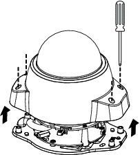
Step 1![]() Use the included screwdriver to loosen the four screws and remove the dome cover.
Use the included screwdriver to loosen the four screws and remove the dome cover.
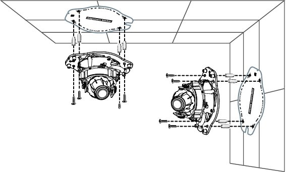
Step 2![]() Apply the included alignment sticker to the ceiling or wall.
Apply the included alignment sticker to the ceiling or wall.
Step 3![]() Using the circle marks on the sticker, drill four (4) pilot holes into the ceiling or wall. Then hammer the included wall anchors into the holes.
Using the circle marks on the sticker, drill four (4) pilot holes into the ceiling or wall. Then hammer the included wall anchors into the holes.
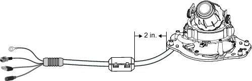
Step 4![]() Attach the included ferrite core to the cable. Ensure that the ferrite core is attached approximately 2 inches (5 cm) away from the IP camera.
Attach the included ferrite core to the cable. Ensure that the ferrite core is attached approximately 2 inches (5 cm) away from the IP camera.
Note![]() The 3421V IP Camera can be mounted with the cable routed through the ceiling/wall or from the side. If you want to feed the cable through the ceiling/wall, drill a 3/4 in. (19 mm) cable hole in the large notch on one end of the alignment sticker, and feed the cable through the hole.
The 3421V IP Camera can be mounted with the cable routed through the ceiling/wall or from the side. If you want to feed the cable through the ceiling/wall, drill a 3/4 in. (19 mm) cable hole in the large notch on one end of the alignment sticker, and feed the cable through the hole.
Step 5![]() Secure the IP camera to the ceiling or wall with four included screws.
Secure the IP camera to the ceiling or wall with four included screws.
Step 6![]() (Optional) Use a mini cable with BNC connector to temporarily attach an NTSC or PAL compliant analog video display device to the analog video out port on the IP camera.
(Optional) Use a mini cable with BNC connector to temporarily attach an NTSC or PAL compliant analog video display device to the analog video out port on the IP camera.
Note![]() The mini cable with BNC adapter is included in the audio/video cables accessory kit, which you can purchase from Cisco (Cisco part number CIVS-AVCABLE).
The mini cable with BNC adapter is included in the audio/video cables accessory kit, which you can purchase from Cisco (Cisco part number CIVS-AVCABLE).
Analog video is enabled by default to allow you to adjust the camera field of view during installation. However, it is not supported as a normal camera feed and is automatically disabled when any of the following camera settings are made:
- The primary video stream frame rate must be set higher than 15 fps.
- The secondary video stream must is enabled.
Note![]() We recommend that you disable analog video after installation. To disable analog video, see the Cisco Video Surveillance 3000 Series IP Camera Configuration Guide.
We recommend that you disable analog video after installation. To disable analog video, see the Cisco Video Surveillance 3000 Series IP Camera Configuration Guide.
Step 7![]() Remove the black cover.
Remove the black cover.
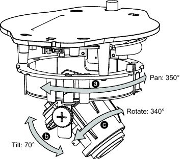
Step 8![]() While viewing video from the IP camera, perform the following steps to adjust the 3-axis field of view:
While viewing video from the IP camera, perform the following steps to adjust the 3-axis field of view:
a.![]() Grip the two tilt adjustment screws and pan the IP camera left or right.
Grip the two tilt adjustment screws and pan the IP camera left or right.
b.![]() Loosen the two thumb screws, tilt the IP camera, then tighten the thumb screws.
Loosen the two thumb screws, tilt the IP camera, then tighten the thumb screws.
c.![]() Rotate the IP camera to adjust the image horizontal orientation.
Rotate the IP camera to adjust the image horizontal orientation.
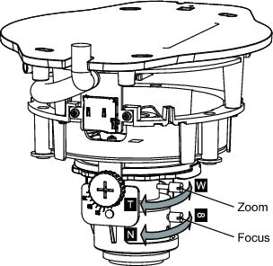
Step 9![]() While viewing video from the IP camera, perform the following steps to adjust the back focus and zoom factor.
While viewing video from the IP camera, perform the following steps to adjust the back focus and zoom factor.
a.![]() Loosen the locking screw on the focus ring, adjust the focal length (from near to infinity [∞]) to achieve a sharp image, then tighten the locking screw.
Loosen the locking screw on the focus ring, adjust the focal length (from near to infinity [∞]) to achieve a sharp image, then tighten the locking screw.
b.![]() Loosen the locking screw on the zoom ring, adjust the zoom factor (from telephoto to wide angle) to achieve the desired field of view, then tighten the locking screw. If the focus is no longer sharp after adjusting the zoom, repeat Step 7a to achieve a sharp image.
Loosen the locking screw on the zoom ring, adjust the zoom factor (from telephoto to wide angle) to achieve the desired field of view, then tighten the locking screw. If the focus is no longer sharp after adjusting the zoom, repeat Step 7a to achieve a sharp image.
Step 10![]() Install the black cover.
Install the black cover.
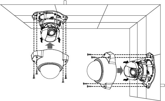
Step 11![]() Attach the dome cover to the IP camera base by aligning it with the mounting holes.
Attach the dome cover to the IP camera base by aligning it with the mounting holes.
Step 12![]() Use the included screwdriver to tighten the four dome cover screws to secure the dome cover to the IP camera. Make sure all parts of the IP camera are securely installed.
Use the included screwdriver to tighten the four dome cover screws to secure the dome cover to the IP camera. Make sure all parts of the IP camera are securely installed.
Step 13![]() If you have an external input device, such as a sensor, connect it to the terminal block.
If you have an external input device, such as a sensor, connect it to the terminal block.
After you install the IP camera, follow the instructions in Chapter 3, “Performing the Initial Setup of the IP Camera” to access the IP camera through your network.
 Feedback