- Preface
- Introducing the Sensor
- Installing IPS-4240 and IPS-4255
- Installing IPS-4260
- Installing IPS 4270-20
- Installing AIM-IPS
- Installing AIP-SSC-5
- Installing AIP-SSM
- Installing IDSM-2
- Installing NME-IPS
- Initializing the Sensor
- Logging In to the Sensor
- Obtaining Software
- Upgrading, Downgrading, and Installing System Images
- Troubleshooting
- Glossary
- Index
Cisco Intrusion Prevention System Appliance and Module Installation Guide for IPS 6.2
Bias-Free Language
The documentation set for this product strives to use bias-free language. For the purposes of this documentation set, bias-free is defined as language that does not imply discrimination based on age, disability, gender, racial identity, ethnic identity, sexual orientation, socioeconomic status, and intersectionality. Exceptions may be present in the documentation due to language that is hardcoded in the user interfaces of the product software, language used based on RFP documentation, or language that is used by a referenced third-party product. Learn more about how Cisco is using Inclusive Language.
- Updated:
- November 21, 2008
Chapter: Installing IPS 4270-20
- IPS 4270-20 BIOS
- Introducing IPS 4270-20
- Supported Interface Cards
- Hardware Bypass
- Front Panel, Back Panel, and Internal Features
- Diagnostic Panel
- Specifications
- Accessories
- Installing the Rail System Kit
- Installing IPS 4270-20
- Removing and Replacing the Chassis Cover
- Accessing the Diagnostic Panel
- Installing and Removing Interface Cards
- Installing and Removing the Power Supply
- Installing and Removing Fans
- Troubleshooting Loose Connections
Installing IPS 4270-20

Note ![]() All IPS platforms allow ten concurrent CLI sessions.
All IPS platforms allow ten concurrent CLI sessions.
This chapter describes IPS 4270-20 and how to install it. It also describes the accessories and how to install them. This chapter contains the following sections:
•![]() Front Panel, Back Panel, and Internal Features
Front Panel, Back Panel, and Internal Features
•![]() Installing the Rail System Kit
Installing the Rail System Kit
•![]() Removing and Replacing the Chassis Cover
Removing and Replacing the Chassis Cover
•![]() Accessing the Diagnostic Panel
Accessing the Diagnostic Panel
•![]() Installing and Removing Interface Cards
Installing and Removing Interface Cards
•![]() Installing and Removing the Power Supply
Installing and Removing the Power Supply
•![]() Troubleshooting Loose Connections
Troubleshooting Loose Connections
IPS 4270-20 BIOS
The BIOS on IPS 4270-20 is specific to IPS 4270-20 and must only be upgraded under instructions from Cisco with BIOS files obtained from the Cisco website. Installing a non-Cisco or third-party BIOS on IPS 4270-20 voids the warranty.
For More Information
For more information on how to obtain instructions and BIOS files from the Cisco website, see Obtaining Cisco IPS Software.
Introducing IPS 4270-20
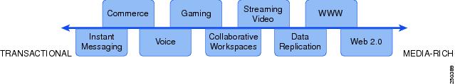
IPS 4270-20 delivers up to 4 Gbps of performance in media-rich environments and 2 Gbps in transactional environments enabling you to protect fully saturated Gigabit networks and aggregate network traffic on multiple sensing interfaces. IPS 4270-20 is also inline ready and has support for both copper and fiber NICs thus providing flexibility of deployment in any environment.
Media-rich environments are characterized by content, such as that seen on popular websites with video and file transfer. Transactional environments are characterized by connections, such as E-commerce, instant messaging, and voice. Figure 4-1 demonstrates the spectrum of media-rich and transactional environments.
Figure 4-1 Media-rich and Transactional Environments
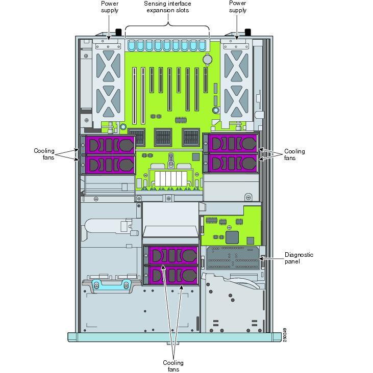
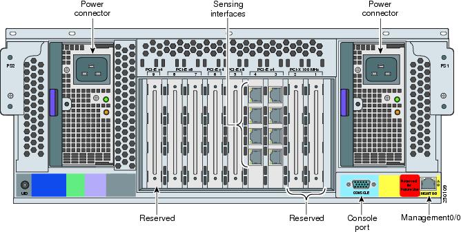
IPS 4270-20 has two built-in GigabitEthernet network ports and nine expansion slots. The network port numbers are numbered from top to bottom beginning with 0 and the expansion slot numbers increase from right to left. The two built-in GigabitEthernet ports are used for management and are called Management0/0 and Management0/1. Management0/1 is reserved for future use. Slots 1 and 2 are reserved for future use. You can populate slots 3 through 8 with supported network interface cards. Slot 9 is populated by a RAID controller card and is not available for use by network interface cards. The sensing interfaces are called GigabitEthernet.
Because of the multiple interfaces on IPS 4270-20, it can cover multiple subnets, each of which have bandwidth requirements in the multi-T3 range or Gigabit range, and the multiple interfaces can be connected directly to the additional monitoring interfaces without needing to SPAN the traffic through a switch.
For improved reliability, IPS 4270-20 uses a compact flash device for storage rather than a hard-disk drive. IPS 4270-20 supports two optional network interface cards, the 2SX interface card with fiber-optic ports, and the 4GE bypass interface card with copper ports that contains the hardware-bypass feature. Initially IPS 4270-20 supports only the built-in interfaces and these two interface cards.
IPS 4270-20 supports a maximum of 16 sensing ports. Any additional configured ports will not be monitored and will not appear in the IPS configuration or statistics and no inline traffic will be forwarded on or between these ports. You receive the following error if you exceed the number of supported ports:
The number of installed network interfaces exceeds the limit of 16. The excess interfaces
are ignored.
Note ![]() If you add a new interface card that exceeds the limit, one or more of the previous sensing interfaces may become disabled.
If you add a new interface card that exceeds the limit, one or more of the previous sensing interfaces may become disabled.
IPS 4270-20 ships with two power supplies, thus supporting a redundant power supply configuration. IPS 4270-20 operates in load-sharing mode when the redundant power supply is installed.
Note ![]() On IPS sensors with multiple processors (for example, the IPS 4260 and IPS 4270-20), packets may be captured out of order in the IP logs and by the packet command. Because the packets are not processed using a single processor, the packets can become out of sync when received from multiple processors.
On IPS sensors with multiple processors (for example, the IPS 4260 and IPS 4270-20), packets may be captured out of order in the IP logs and by the packet command. Because the packets are not processed using a single processor, the packets can become out of sync when received from multiple processors.
For More Information
•![]() For more information on sensor interfaces, see Sensor Interfaces.
For more information on sensor interfaces, see Sensor Interfaces.
•![]() For more information on the supported interface cards, see Supported Interface Cards.
For more information on the supported interface cards, see Supported Interface Cards.
•![]() For more information on the 4GE bypass interface card, see Hardware Bypass.
For more information on the 4GE bypass interface card, see Hardware Bypass.
•![]() For more information about the power supplies, see Installing and Removing the Power Supply.
For more information about the power supplies, see Installing and Removing the Power Supply.
Supported Interface Cards
IPS 4270-20 supports three interface cards: the 4GE bypass interface card, the 2SX interface card, and the 10GE interface card.
4GE Bypass Interface Card
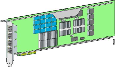
The 4GE bypass interface card (part numbers IPS-4GE-BP-INT and IPS-4GE-BP-INT=) provides four 10/100/1000BASE-T (4GE) monitoring interfaces. The IPS 4270-20 supports up to four 4GE bypass interface cards for a total of sixteen GE bypass interfaces. The 4GE bypass interface card supports hardware bypass.
Figure 4-2 shows the 4GE bypass interface card.
Figure 4-2 4GE Bypass Interface Card
2SX Interface Card
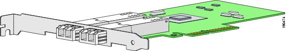
The 2SX interface card (part numbers IPS-2SX-INT and IPS-2SX-INT=) provides two 1000BASE-SX (fiber) monitoring interfaces. The IPS 4270-20 supports up to six 2SX interface cards for a total of twelve SX interfaces. The 2SX card ports require a multi-mode fiber cable with an LC connector to connect to the SX interface of the sensor. The 2SX interface card does not support hardware bypass.
Figure 4-3 shows the 2SX interface card.
Figure 4-3 2SX Interface Card
10GE Interface Card
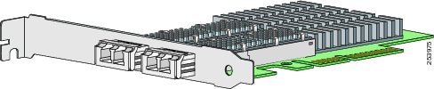
The 10GE interface card (part numbers IPS-2X10GE-SR-INT and IPS-2X10GE-SR-INT=) provides two 10000 Base-SX (fiber) interfaces. The IPS 4270-20 supports up to two 10GE interface cards for a total of four 10GE fiber interfaces. The card ports require a multi-mode fiber cable with an LC connector to connect to the SX interface of IPS 4270-20. The 10GE interface card does not support hardware bypass.
Figure 4-4 shows the 10GE interface card.
Figure 4-4 10GE Interface Card
GigabitEthernetslot_number/port_number is the expansion card interface naming convention for IPS 4270-20. The slot number is shown above the slot in the chassis and the port number is numbered from top to bottom starting with 0.
For More Information
For the procedure for installing and removing interface cards, see Installing and Removing Interface Cards.
Hardware Bypass
This section describes the 4GE bypass interface card and its configuration restrictions. It contains the following topics:
•![]() Hardware Bypass Configuration Restrictions
Hardware Bypass Configuration Restrictions
•![]() Hardware Bypass and Link Changes and Drops
Hardware Bypass and Link Changes and Drops
4GE Bypass Interface Card
IPS 4270-20 supports the 4-port GigabitEthernet card (part number IPS-4GE-BP-INT=) with hardware bypass. This 4GE bypass interface card supports hardware bypass only between ports 0 and 1 and between ports 2 and 3.
Note ![]() To disable hardware bypass, pair the interfaces in any other combination, for example 2/0<->2/2 and 2/1<->2/3.
To disable hardware bypass, pair the interfaces in any other combination, for example 2/0<->2/2 and 2/1<->2/3.
Hardware bypass complements the existing software bypass feature in Cisco IPS. The following conditions apply to hardware bypass and software bypass:
•![]() When bypass is set to OFF, software bypass is not active.
When bypass is set to OFF, software bypass is not active.
For each inline interface for which hardware bypass is available, the component interfaces are set to disable the fail-open capability. If SensorApp fails, the sensor is powered off, reset, or if the NIC interface drivers fail or are unloaded, the paired interfaces enter the fail-closed state (no traffic flows through inline interface or inline VLAN subinterfaces).
•![]() When bypass is set to ON, software bypass is active.
When bypass is set to ON, software bypass is active.
Software bypass forwards packets between the paired physical interfaces in each inline interface and between the paired VLANs in each inline VLAN subinterface. For each inline interface on which hardware bypass is available, the component interfaces are set to standby mode. If the sensor is powered off, reset, or if the NIC interfaces fail or are unloaded, those paired interfaces enter fail-open state in hardware (traffic flows unimpeded through inline interface). Any other inline interfaces enter fail-closed state.
•![]() When bypass is set to AUTO (traffic flows without inspection), software bypass is activated if SensorApp fails.
When bypass is set to AUTO (traffic flows without inspection), software bypass is activated if SensorApp fails.
For each inline interface on which hardware bypass is available, the component interfaces are set to standby mode. If the sensor is powered off, reset, or if the NIC interfaces fail or are unloaded, those paired interfaces enter fail-open state in hardware. Any other inline interfaces enter the fail-closed state.
Note ![]() To test fail-over, set the bypass mode to ON or AUTO, create one or more inline interfaces and power down the sensor and verify that traffic still flows through the inline path.
To test fail-over, set the bypass mode to ON or AUTO, create one or more inline interfaces and power down the sensor and verify that traffic still flows through the inline path.
For More Information
For the procedure for installing and removing the 4GE bypass interface card, see Installing and Removing Interface Cards.
Hardware Bypass Configuration Restrictions
To use the hardware bypass feature on the 4GE bypass interface card, you must pair interfaces to support the hardware design of the card. If you create an inline interface that pairs a hardware-bypass-capable interface with an interface that violates one or more of the hardware-bypass configuration restrictions, hardware bypass is deactivated on the inline interface and you receive a warning message similar to the following:
Hardware bypass functionality is not available on Inline-interface pair0.
Physical-interface GigabitEthernet2/0 is capable of performing hardware bypass only when
paired with GigabitEthernet2/1, and both interfaces are enabled and configured with the
same speed and duplex settings.
The following configuration restrictions apply to hardware bypass:
•![]() The 4-port bypass card is only supported on IPS 4270-20.
The 4-port bypass card is only supported on IPS 4270-20.
•![]() Fail-open hardware bypass only works on inline interfaces (interface pairs), not on inline VLAN pairs.
Fail-open hardware bypass only works on inline interfaces (interface pairs), not on inline VLAN pairs.
•![]() Fail-open hardware bypass is available on an inline interface if all of the following conditions are met:
Fail-open hardware bypass is available on an inline interface if all of the following conditions are met:
–![]() Both of the physical interfaces support hardware bypass.
Both of the physical interfaces support hardware bypass.
–![]() Both of the physical interfaces are on the same interface card.
Both of the physical interfaces are on the same interface card.
–![]() The two physical interfaces are associated in hardware as a bypass pair.
The two physical interfaces are associated in hardware as a bypass pair.
–![]() The speed and duplex settings are identical on the physical interfaces.
The speed and duplex settings are identical on the physical interfaces.
–![]() Both of the interfaces are administratively enabled.
Both of the interfaces are administratively enabled.
•![]() Autonegotiation must be set on MDI/X switch ports connected to IPS 4270-20.
Autonegotiation must be set on MDI/X switch ports connected to IPS 4270-20.
You must configure both the sensor ports and the switch ports for autonegotiation for hardware bypass to work. The switch ports must support MDI/X, which automatically reverses the transmit and receive lines if necessary to correct any cabling problems. The sensor is only guaranteed to operate correctly with the switch if both of them are configured for identical speed and duplex, which means that the sensor must be set for autonegotiation too.
Hardware Bypass and Link Changes and Drops
Properly configuring and deploying hardware bypass protects against complete link failure if the IPS appliance experiences a power loss, critical hardware failure, or is rebooted; however, a link status change still occurs when hardware bypass engages (and again when it disengages).
During engagement, the interface card disconnects both physical connections from itself and bridges them together. The interfaces of the connected devices can then negotiate the link and traffic forwarding can resume. Once the appliance is back online, hardware bypass disengages and the interface card interrupts the bypass and reconnects the links back to itself. The interface card then negotiates both links and traffic resumes.
There is no built-in way to completely avoid link status changes and drops. However, you can greatly reduce the interruption time (in some cases to sub-second times) by doing the following:
•![]() Make sure you use CAT 5e/6-certified cabling for all connections.
Make sure you use CAT 5e/6-certified cabling for all connections.
•![]() Make sure the interfaces of the connected devices are configured to match the interfaces of the appliance for speed/duplex negotiation (auto/auto).
Make sure the interfaces of the connected devices are configured to match the interfaces of the appliance for speed/duplex negotiation (auto/auto).
•![]() Enable portfast on connected switchports to reduce spanning-tree forwarding delays.
Enable portfast on connected switchports to reduce spanning-tree forwarding delays.
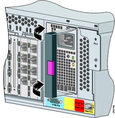
Front Panel, Back Panel, and Internal Features
This section describes the IPS 4270-20 front panel, back panel, and internal features and indicators.
Figure 4-5 shows the front view of IPS 4270-20.
Figure 4-5 IPS 4270-20 Front View
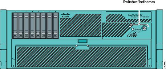
Figure 4-6 shows the front panel switches and indicators.
Figure 4-6 IPS 4270-20 Front Panel Switches and Indicators
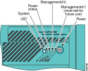
Table 4-1 describes the front panel switches and indicators on IPS 4270-20.
Figure 4-7 shows the back view of IPS 4270-20.
Figure 4-7 IPS 4270-20 Back Panel Features
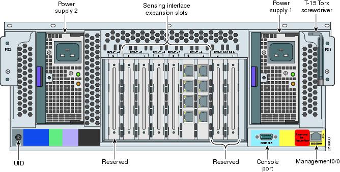
Figure 4-8 shows the built-in Ethernet port, which has two indicators per port, and the power supply indicators.
Figure 4-8 Ethernet Port Indicators
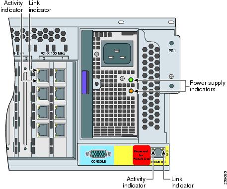
Table 4-2 describes the Ethernet port indicators.
Table 4-3 describes the power supply indicators.
Figure 4-9 IPS 4270-20 Internal Components
Diagnostic Panel
The front panel health indicators only indicate the current hardware status. The Diagnostic Panel indicators identify components experiencing an error, event, or failure. All indicators are off unless one of the component fails.
Note ![]() When you remove the chassis cover to view the Diagnostic Panel, leave IPS 4270-20 powered on. Powering off IPS 4270-20 clears the Diagnostic Panel indicators.
When you remove the chassis cover to view the Diagnostic Panel, leave IPS 4270-20 powered on. Powering off IPS 4270-20 clears the Diagnostic Panel indicators.
Figure 4-10 shows the Diagnostic Panel.
Figure 4-10 Diagnostic Panel
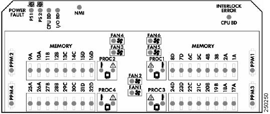
Table 4-4 lists the indicators that display health status for each component:
For More Information
•![]() For the location of the Diagnostic Panel in the IPS 4270-20 chassis, see Figure 4-9.
For the location of the Diagnostic Panel in the IPS 4270-20 chassis, see Figure 4-9.
•![]() For information on how to access the Diagnostic Panel, see Accessing the Diagnostic Panel.
For information on how to access the Diagnostic Panel, see Accessing the Diagnostic Panel.
Specifications
Table 4-5 lists the specifications for IPS 4270-20.
|
|
|
Height |
6.94 in. (17.6 cm) |
Width |
19.0 in. (46.3 cm) |
Depth |
26.5 in. (67.3 cm) |
Weight |
80 lb (36.3 kg) |
Form factor |
4 RU, standard 19-inch rack-mountable |
|
|
|
Rated input voltage |
100 to 127 VAC |
Rated input frequency |
50 to 60 Hz |
Rated input power |
1161W @ 100 VAC |
Rated input current |
12A (100 VAC) |
Maximum heat dissipation |
3960 BTU/hr (100 VAC) |
Power supply output |
910 W (low line) |
|
|
|
Temperature |
Operating 50 to 95°F (10 to 35°C)1 |
Maximum wet bulb temperature |
82.4°F (28°C) |
Relative humidity (noncondensing) |
Operating 10% to 90% |
Altitude |
Operating 0 to 10,000 ft (3050 m) |
Shock |
Operating Half-sine 2 G, 11 ms pulse, 100 pulses |
Vibration |
2.2 Grms, 10 minutes per axis on all three axes |
1 At sea level with an altitude derating of 1.8°F per every 1000 ft (1.0°C per every 3.0m) above sea level to a maximum of 10,000 ft (3050 m). no direct sustained sunlight. |
Accessories
The IPS 4270-20 accessories kit contains the following:
•![]() DB-9 connector
DB-9 connector
•![]() DB-9/RJ-45 console cable
DB-9/RJ-45 console cable
•![]() Two Ethernet RJ-45 cables
Two Ethernet RJ-45 cables
•![]() Regulatory Compliance and Safety Information for the Cisco Intrusion Detection and Prevention System 4200 Series Appliance Sensor
Regulatory Compliance and Safety Information for the Cisco Intrusion Detection and Prevention System 4200 Series Appliance Sensor
•![]() Documentation Roadmap for Cisco Intrusion Prevention System
Documentation Roadmap for Cisco Intrusion Prevention System
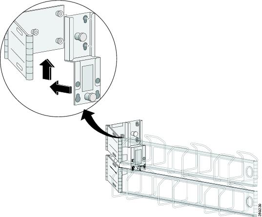
Installing the Rail System Kit
You can install IPS 4270-20 in a 4-post rack. This section describes how to install IPS 4270-20 in a rack, and contains the following sections:
•![]() Understanding the Rail System Kit
Understanding the Rail System Kit
•![]() Space and Airflow Requirements
Space and Airflow Requirements
•![]() Installing IPS 4270-20 in the Rack
Installing IPS 4270-20 in the Rack
•![]() Extending IPS 4270-20 from the Rack
Extending IPS 4270-20 from the Rack
•![]() Installing the Cable Management Arm
Installing the Cable Management Arm
•![]() Converting the Cable Management Arm
Converting the Cable Management Arm
Understanding the Rail System Kit
This rail system supports a variety of products that can be installed in round-, square, or threaded-hole racks. The following illustration shows the three rack hole-types. Use Figure 4-11 to identify your rack type and then follow the installation steps accordingly.
Figure 4-11 Round-, Square-, and Threaded-Hole Racks
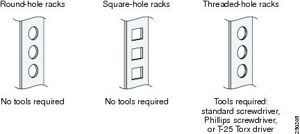
No tools are required for the round- and square-hole racks. You may need screws that fit the threaded-hole rack and a driver for those screws.You need a standard screwdriver to remove the round- and square-hole studs from the slide assemblies when you install the security appliance in a threaded-whole rack.
This rail system supports a minimum rack depth of 24 in. (60.96 cm) and a maximum rack depth of 36.5 in. (92.71 cm).
Rail System Kit Contents
The rail system kit contains the following items:
•![]() Two slide assemblies
Two slide assemblies
•![]() Two chassis rails
Two chassis rails
•![]() Four Velcro straps
Four Velcro straps
•![]() Six zip ties
Six zip ties
•![]() One cable management arm
One cable management arm
•![]() A package of miscellaneous parts (screws, and so forth)
A package of miscellaneous parts (screws, and so forth)
•![]() One cable management arm stop bracket
One cable management arm stop bracket
Space and Airflow Requirements
To allow for servicing and adequate airflow, follow these space and airflow requirements when choosing where to place a rack:
•![]() Leave a minimum clearance of 25 in. (63.5 cm) in front of the rack.
Leave a minimum clearance of 25 in. (63.5 cm) in front of the rack.
•![]() Leave a minimum clearance of 30 in. (76.2 cm) behind the rack.
Leave a minimum clearance of 30 in. (76.2 cm) behind the rack.
•![]() Leave a minimum clearance of 48 in. (121.9 cm) from the back of the rack to the back of another rack or row of racks.
Leave a minimum clearance of 48 in. (121.9 cm) from the back of the rack to the back of another rack or row of racks.
IPS 4270-20 draws in cool air through the front and expels warm air through the back. The front and back rack doors must be adequately ventilated to allow ambient room air to enter the chassis and the back must be adequately ventilated to allow warm air to escape from the chassis.
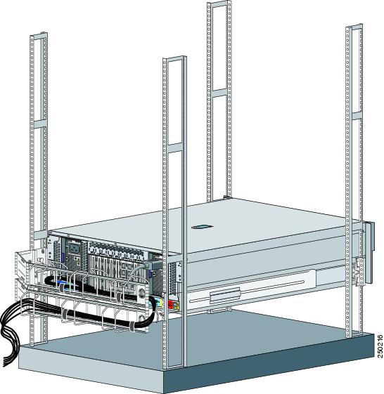
Installing IPS 4270-20 in the Rack
 |
Warning |
To install IPS 4270-20 in the rack, follow these steps:
Step 1 ![]() Attach the chassis side rail to IPS 4270-20 by aligning the chassis rail to the stud on IPS 4270-20, pressing the chassis side rail in to the stud, and then sliding the chassis side rail backwards until you hear the latch catch.
Attach the chassis side rail to IPS 4270-20 by aligning the chassis rail to the stud on IPS 4270-20, pressing the chassis side rail in to the stud, and then sliding the chassis side rail backwards until you hear the latch catch.
Note ![]() The tapered end of the chassis side rail should be at the back of IPS 4270-20. The chassis side rail is held in place by the inner latch.
The tapered end of the chassis side rail should be at the back of IPS 4270-20. The chassis side rail is held in place by the inner latch.
Step 2 ![]() Repeat Step 1 for each chassis side rail.
Repeat Step 1 for each chassis side rail.
Step 3 ![]() To remove the chassis side rail, lift the latch, and slide the rail forward.
To remove the chassis side rail, lift the latch, and slide the rail forward.
Step 4 ![]() If you are installing IPS 4270-20 in a shallow rack, one that is less than 28.5 in. (72.39 cm), remove the screw from the inside of the slide assembly before continuing with Step 5.
If you are installing IPS 4270-20 in a shallow rack, one that is less than 28.5 in. (72.39 cm), remove the screw from the inside of the slide assembly before continuing with Step 5.
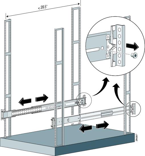
Step 5 ![]() Attach the slide assemblies to the rack.
Attach the slide assemblies to the rack.
For round- and square-hole racks:
a. ![]() Line up the studs on the slide assembly with the holes on the inside of the rack and snap in to place.
Line up the studs on the slide assembly with the holes on the inside of the rack and snap in to place.
b. ![]() Adjust the slide assembly lengthwise to fit the rack.
Adjust the slide assembly lengthwise to fit the rack.
The spring latch locks the slide assembly into position.
c. ![]() Repeat for each slide assembly.
Repeat for each slide assembly.
Make sure the slide assemblies line up with each other in the rack.
d. ![]() Lift the spring latch to release the slide assembly if you need to reposition it.
Lift the spring latch to release the slide assembly if you need to reposition it.
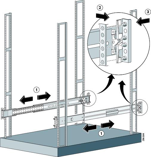
For threaded-hole racks:
a. ![]() Remove the eight round- or square-hole studs on each slide assembly using a standard screwdriver.
Remove the eight round- or square-hole studs on each slide assembly using a standard screwdriver.
Note ![]() You may need a pair of pliers to hold the retaining nut.
You may need a pair of pliers to hold the retaining nut.
b. ![]() Line up the bracket on the slide assembly with the rack holes, install two screws (top and bottom) on each end of the slide assembly.
Line up the bracket on the slide assembly with the rack holes, install two screws (top and bottom) on each end of the slide assembly.
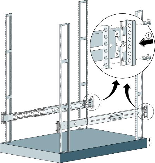
c. ![]() Repeat for each slide assembly.
Repeat for each slide assembly.
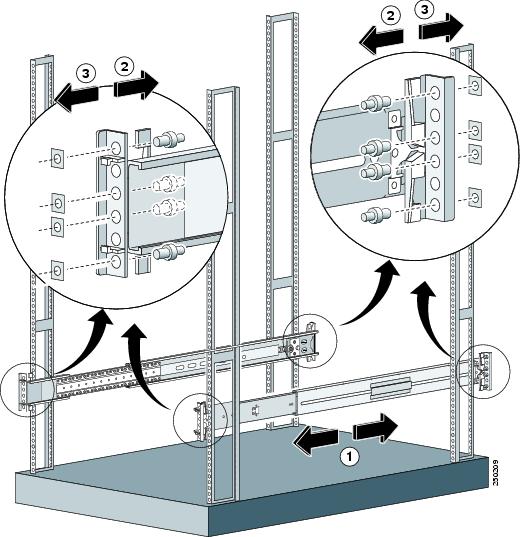
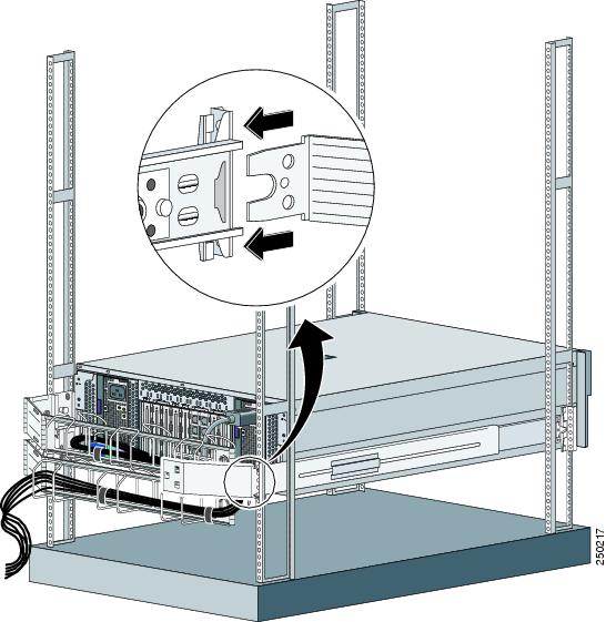
Step 6 ![]() Extend the slide assemblies out of the rack.
Extend the slide assemblies out of the rack.
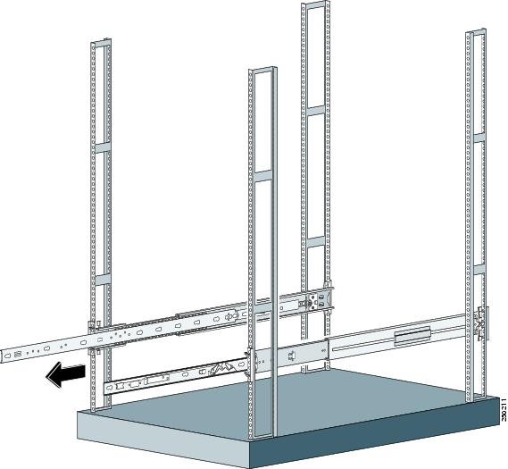
Step 7 ![]() Align the chassis side rails on IPS 4270-20 with the slide assembly on both sides of the rack, release the blue slide tab (by either pulling the tab forward or pushing the tab back), and carefully push IPS 4270-20 in to place.
Align the chassis side rails on IPS 4270-20 with the slide assembly on both sides of the rack, release the blue slide tab (by either pulling the tab forward or pushing the tab back), and carefully push IPS 4270-20 in to place.

Step 8 ![]() If you are using the cable management arm, install it before you connect and route any cables.
If you are using the cable management arm, install it before you connect and route any cables.
Note ![]() You may also need longer cables when the arm is installed (an extra length of around 3 feet is required).
You may also need longer cables when the arm is installed (an extra length of around 3 feet is required).
Step 9 ![]() Install the electrical cables at the back of IPS 4270-20.
Install the electrical cables at the back of IPS 4270-20.
For More Information
•![]() For the procedure for installing the cable management arm, see Installing the Cable Management Arm.
For the procedure for installing the cable management arm, see Installing the Cable Management Arm.
•![]() For information on installing connections to IPS 4270-20, see Installing IPS 4270-20.
For information on installing connections to IPS 4270-20, see Installing IPS 4270-20.
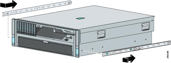
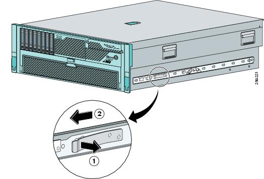
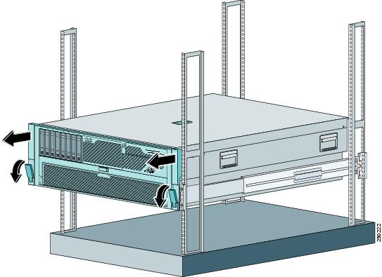
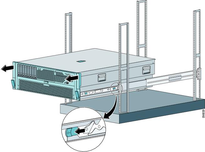
Extending IPS 4270-20 from the Rack
You can extend IPS 4270-20 from the rack for service or removal.
To extend IPS 4270-20 from the rack, follow these steps:
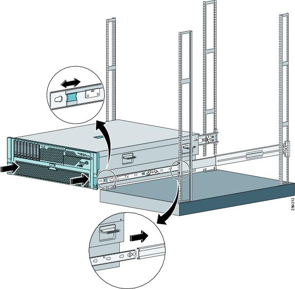
Step 1 ![]() Pull the quick-release levers on each side of the front bezel of IPS 4270-20 to release it from the rack and extend it on the rack rails until the rail-release latches engage.
Pull the quick-release levers on each side of the front bezel of IPS 4270-20 to release it from the rack and extend it on the rack rails until the rail-release latches engage.
Note ![]() The release latches lock in to place when the rails are fully extended.
The release latches lock in to place when the rails are fully extended.
Step 2 ![]() After performing the installation or maintenance procedure, slide IPS 4270-20 in to the rack by pressing the rail-release latches.
After performing the installation or maintenance procedure, slide IPS 4270-20 in to the rack by pressing the rail-release latches.
Step 3 ![]() To completely remove IPS 4270-20 from the rack, disconnect the cables from the back of IPS 4270-20, push the release tab in the middle of the slide assembly forward, and pull IPS 4270-20 from the rack.
To completely remove IPS 4270-20 from the rack, disconnect the cables from the back of IPS 4270-20, push the release tab in the middle of the slide assembly forward, and pull IPS 4270-20 from the rack.
Installing the Cable Management Arm
Note ![]() To hinge the cable management arm on the back right-hand side of the rack, see Converting the Cable Management Arm.
To hinge the cable management arm on the back right-hand side of the rack, see Converting the Cable Management Arm.
To install the cable management arm, follow these steps:
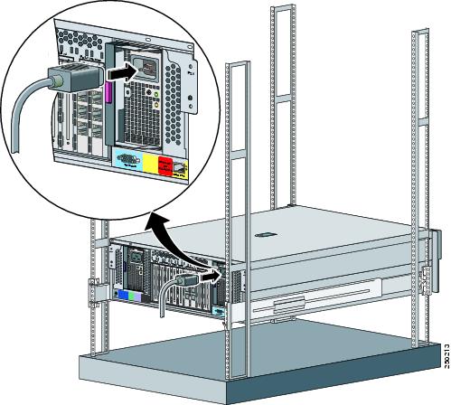
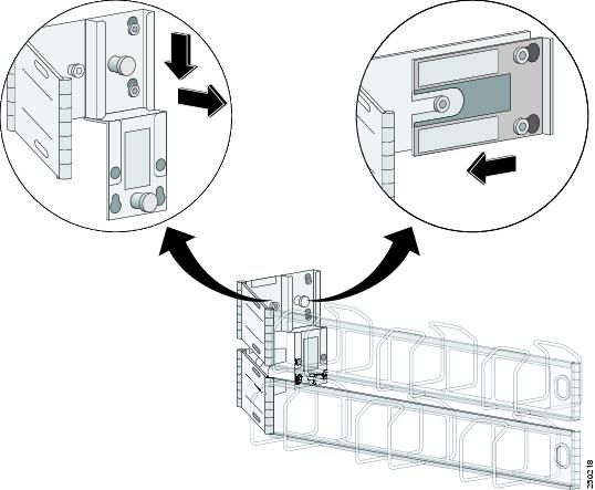
Step 1 ![]() Align the slide bracket on the cable management arm with the stud on the back of IPS 4270-20 and align the two studs at the back of the chassis side rail, then slide down and lock in to place.
Align the slide bracket on the cable management arm with the stud on the back of IPS 4270-20 and align the two studs at the back of the chassis side rail, then slide down and lock in to place.
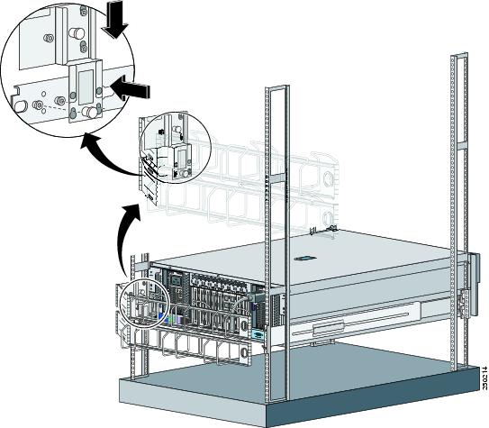
Step 2 ![]() Attach the cable trough to the back of the rack by pushing the lower metal tab on the cable management arm in to the slide assembly, then lifting the spring pin to lock it in to place.
Attach the cable trough to the back of the rack by pushing the lower metal tab on the cable management arm in to the slide assembly, then lifting the spring pin to lock it in to place.
Note ![]() When properly installed, the cable management arm is attached to IPS 4270-20 and the rack rail.
When properly installed, the cable management arm is attached to IPS 4270-20 and the rack rail.
Step 3 ![]() Route the cables through the cable trough and secure the cables with the Velcro straps and black tie wraps.
Route the cables through the cable trough and secure the cables with the Velcro straps and black tie wraps.
Note ![]() After you route the cables through the cable management arm, make sure the cables are not pulled tight when IPS 4270-20 is fully extended.
After you route the cables through the cable management arm, make sure the cables are not pulled tight when IPS 4270-20 is fully extended.
Step 4 ![]() Attach the cable management arm stop bracket to the ride side of the back of the rack by inserting the stop bracket into the cable management arm bracket.
Attach the cable management arm stop bracket to the ride side of the back of the rack by inserting the stop bracket into the cable management arm bracket.
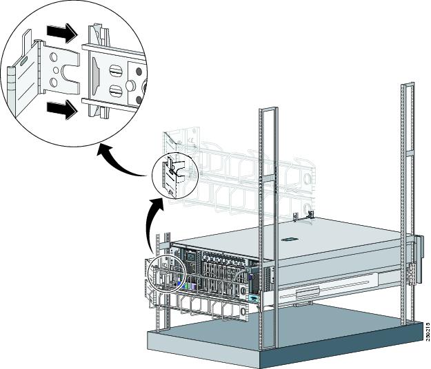
Converting the Cable Management Arm
Note ![]() The cable management arm is designed for ambidextrous use. You can convert the cable management arm from a left-hand swing to a right-hand swing.
The cable management arm is designed for ambidextrous use. You can convert the cable management arm from a left-hand swing to a right-hand swing.
Note ![]() Make sure to orient the management arm with the cable trough facing upward.
Make sure to orient the management arm with the cable trough facing upward.
To convert the cable management arm swing, follow these steps:
Step 1 ![]() Pull up the spring pin and slide the bracket off the cable management arm.
Pull up the spring pin and slide the bracket off the cable management arm.
Step 2 ![]() Remove the bottom sliding bracket and flip it over to the top of the bracket aligning the studs.
Remove the bottom sliding bracket and flip it over to the top of the bracket aligning the studs.
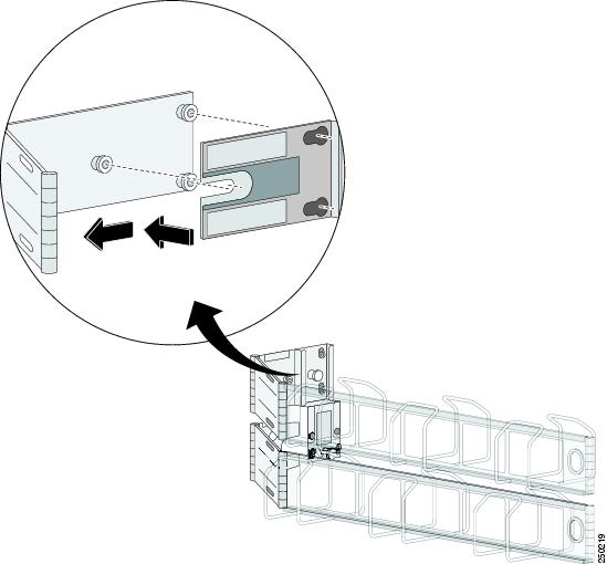
Step 3 ![]() On the other side of the sliding bracket, align the spring pin with the studs and key holes, and slide until the pin snaps in to place.
On the other side of the sliding bracket, align the spring pin with the studs and key holes, and slide until the pin snaps in to place.
Note ![]() The sliding bracket only fits one way because the hole for the spring pin is offset.
The sliding bracket only fits one way because the hole for the spring pin is offset.
Installing IPS 4270-20
|
Warning This warning symbol means danger. You are in a situation that could cause bodily injury. Before you work on any equipment, be aware of the hazards involved with electrical circuitry and be familiar with standard practices for preventing accidents. Use the statement number provided at the end of each warning to locate its translation in the translated safety warnings that accompanied this device. Statement 1071 SAVE THESE INSTRUCTIONS |
|
Warning |
To install IPS 4270-20 on the network, follow these steps:
Step 1 ![]() Position IPS 4270-20 on the network.
Position IPS 4270-20 on the network.
Step 2 ![]() Install IPS 4270-20 in a rack, if you are rack mounting it.
Install IPS 4270-20 in a rack, if you are rack mounting it.
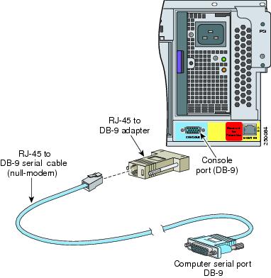
Step 3 ![]() Connect the cable as shown in Step 4 so that you have either a DB-9 connector on one end as required by the serial port for your computer, and the other end is the RJ-45 connector.
Connect the cable as shown in Step 4 so that you have either a DB-9 connector on one end as required by the serial port for your computer, and the other end is the RJ-45 connector.
Note ![]() Use the console port to connect to a computer to enter configuration commands. Locate the serial cable from the accessory kit. The serial cable assembly consists of a 180/rollover cable with RJ-45 connectors (DB-9 connector adapter PN 74-0495-01).
Use the console port to connect to a computer to enter configuration commands. Locate the serial cable from the accessory kit. The serial cable assembly consists of a 180/rollover cable with RJ-45 connectors (DB-9 connector adapter PN 74-0495-01).
Note ![]() You can use a 180/rollover or straight-through patch cable to connect the appliance to a port on a terminal server with RJ-45 or hydra cable assembly connections. Connect the appropriate cable from the console port on the appliance to a port on the terminal server.
You can use a 180/rollover or straight-through patch cable to connect the appliance to a port on a terminal server with RJ-45 or hydra cable assembly connections. Connect the appropriate cable from the console port on the appliance to a port on the terminal server.
Step 4 ![]() Connect the RJ-45 to DB-9 adapter connector to the console port and connect the other end to the DB-9 connector on your computer.
Connect the RJ-45 to DB-9 adapter connector to the console port and connect the other end to the DB-9 connector on your computer.
Step 5 ![]() Attach the network cables to the interface ports:
Attach the network cables to the interface ports:
•![]() Management0/0 (MGMT0/0) is the command and control port.
Management0/0 (MGMT0/0) is the command and control port.
•![]() GigabitEthernetslot_number/port_number through GigabitEthernetslot_number/port_number are the expansion ports.
GigabitEthernetslot_number/port_number through GigabitEthernetslot_number/port_number are the expansion ports.
Step 6 ![]() Attach the power cables (there are two power supplies) to IPS 4270-20 and plug them in to a power source (a UPS is recommended).
Attach the power cables (there are two power supplies) to IPS 4270-20 and plug them in to a power source (a UPS is recommended).
Step 7 ![]() Power on IPS 4270-20.
Power on IPS 4270-20.
Step 8 ![]() Initialize IPS 4270-20.
Initialize IPS 4270-20.
Step 9 ![]() Upgrade IPS 4270-20 with the most recent Cisco IPS software.
Upgrade IPS 4270-20 with the most recent Cisco IPS software.
You are now ready to configure intrusion prevention on IPS 4270-20.
For More Information
•![]() For more information on working with electrical power and in an ESD environment, see Site and Safety Guidelines.
For more information on working with electrical power and in an ESD environment, see Site and Safety Guidelines.
•![]() For more information on the best place to position your sensor on the network, see Your Network Topology.
For more information on the best place to position your sensor on the network, see Your Network Topology.
•![]() For the procedure for installing IPS 4270-20 in a rack, see Installing IPS 4270-20 in the Rack.
For the procedure for installing IPS 4270-20 in a rack, see Installing IPS 4270-20 in the Rack.
•![]() For the instructions for setting up a terminal server, see Connecting an Appliance to a Terminal Server.
For the instructions for setting up a terminal server, see Connecting an Appliance to a Terminal Server.
•![]() For the procedure for using the setup command to initialize IPS 4270-20, see Initializing the Sensor.
For the procedure for using the setup command to initialize IPS 4270-20, see Initializing the Sensor.
•![]() For the procedure for obtaining the most recent Cisco IPS software, see Obtaining Cisco IPS Software.
For the procedure for obtaining the most recent Cisco IPS software, see Obtaining Cisco IPS Software.
•![]() For the procedure for using HTTPS to log in to IDM, refer to Logging In to IDM.
For the procedure for using HTTPS to log in to IDM, refer to Logging In to IDM.
•![]() For the procedures for configuring intrusion prevention on your sensor, refer to the following guides:
For the procedures for configuring intrusion prevention on your sensor, refer to the following guides:
–![]() Installing and Using Cisco Intrusion Prevention System Device Manager 6.2
Installing and Using Cisco Intrusion Prevention System Device Manager 6.2
–![]() Installing and Using Cisco Intrusion Prevention System Manager Express 6.2
Installing and Using Cisco Intrusion Prevention System Manager Express 6.2
–![]() Configuring the Cisco Intrusion Prevention System Sensor Using the Command Line Interface 6.2
Configuring the Cisco Intrusion Prevention System Sensor Using the Command Line Interface 6.2
Removing and Replacing the Chassis Cover
|
Warning |
|
Warning |
|
Warning |
|
Warning |
Note ![]() Removing the appliance chassis cover does not affect your Cisco warranty. Upgrading IPS 4270-20 does not require any special tools and does not create any radio frequency leaks.
Removing the appliance chassis cover does not affect your Cisco warranty. Upgrading IPS 4270-20 does not require any special tools and does not create any radio frequency leaks.
To remove and replace the chassis cover, follow these steps:
Step 1 ![]() Log in to the CLI.
Log in to the CLI.
Step 2 ![]() Prepare IPS 4270-20 to be powered off:
Prepare IPS 4270-20 to be powered off:
sensor# reset powerdown
Wait for the power down message before continuing with Step 3.
Note ![]() You can also power down IPS 4270-20 using IDM or IME.
You can also power down IPS 4270-20 using IDM or IME.
Step 3 ![]() Power off IPS 4270-20.
Power off IPS 4270-20.
Step 4 ![]() Remove both power cables from IPS 4270-20.
Remove both power cables from IPS 4270-20.
Step 5 ![]() Extend IPS 4270-20 out of the rack if it is rack-mounted.
Extend IPS 4270-20 out of the rack if it is rack-mounted.
Step 6 ![]() Make sure IPS 4270-20 is in an ESD-controlled environment.
Make sure IPS 4270-20 is in an ESD-controlled environment.
Step 7 ![]() If the locking latch is locked, use the T-15 Torx screwdriver located on the back of the chassis to unlock it. Turn the locking screw a quarter of a turn counterclockwise to unlock it.
If the locking latch is locked, use the T-15 Torx screwdriver located on the back of the chassis to unlock it. Turn the locking screw a quarter of a turn counterclockwise to unlock it.
Step 8 ![]() Lift up the cover latch on the top of the chassis.
Lift up the cover latch on the top of the chassis.
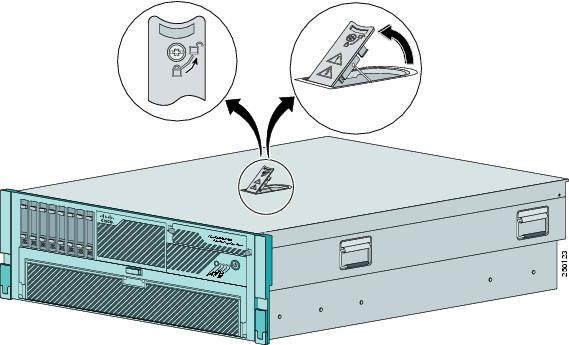
Step 9 ![]() Slide the chassis cover back and up to remove it.
Slide the chassis cover back and up to remove it.
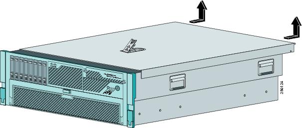
Step 10 ![]() To replace the chassis cover, position it on top of the chassis and slide it on. Push down on the cover latch to lock into place.
To replace the chassis cover, position it on top of the chassis and slide it on. Push down on the cover latch to lock into place.
Note ![]() Make sure the chassis cover is securely locked in to place before powering up IPS 4270-20.
Make sure the chassis cover is securely locked in to place before powering up IPS 4270-20.
Step 11 ![]() Reattach the power cables to IPS 4270-20.
Reattach the power cables to IPS 4270-20.
Step 12 ![]() Reinstall IPS 4270-20 in a rack, on a desktop, or on a table, or extend it back in to the rack.
Reinstall IPS 4270-20 in a rack, on a desktop, or on a table, or extend it back in to the rack.
Step 13 ![]() Power on IPS 4270-20.
Power on IPS 4270-20.
For More Information
•![]() For the procedure extending IPS 4270-20 from the rack, see Extending IPS 4270-20 from the Rack.
For the procedure extending IPS 4270-20 from the rack, see Extending IPS 4270-20 from the Rack.
•![]() For more information on working in an ESD-controlled environment, see Working in an ESD Environment.
For more information on working in an ESD-controlled environment, see Working in an ESD Environment.
•![]() For the IDM procedure for powering down IPS 4270-20, refer to Rebooting the Sensor; for the IME procedure for powering down IPS 4270-20, refer to Rebooting the Sensor.
For the IDM procedure for powering down IPS 4270-20, refer to Rebooting the Sensor; for the IME procedure for powering down IPS 4270-20, refer to Rebooting the Sensor.
•![]() For an illustration of the screwdriver and where it is located, see Figure 4-7.
For an illustration of the screwdriver and where it is located, see Figure 4-7.
•![]() For the procedure for installing the power cables on IPS 4270-20, see Installing IPS 4270-20.
For the procedure for installing the power cables on IPS 4270-20, see Installing IPS 4270-20.
•![]() If you are reinstalling IPS 4270-20 in a rack, see Installing the Rail System Kit.
If you are reinstalling IPS 4270-20 in a rack, see Installing the Rail System Kit.
Accessing the Diagnostic Panel
Note ![]() When you remove the chassis cover to view the Diagnostic Panel, leave IPS 4270-20 powered on. Powering off IPS 4270-20 clears the Diagnostic Panel indicators.
When you remove the chassis cover to view the Diagnostic Panel, leave IPS 4270-20 powered on. Powering off IPS 4270-20 clears the Diagnostic Panel indicators.
To access the Diagnostic Panel, follow these steps:
Step 1 ![]() Extend IPS 4270-20 from the rack.
Extend IPS 4270-20 from the rack.
Step 2 ![]() Remove the chassis cover.
Remove the chassis cover.
Step 3 ![]() Locate the Diagnostic Panel.
Locate the Diagnostic Panel.
Follow the instructions in this chapter to remove and install failed components. For aid in troubleshooting, use the internal health indicators information when contacting TAC.
For More Information
•![]() For the procedure for extending IPS 4270-20 from the rack, see Extending IPS 4270-20 from the Rack.
For the procedure for extending IPS 4270-20 from the rack, see Extending IPS 4270-20 from the Rack.
•![]() For the procedure for removing the chassis cover, see Removing and Replacing the Chassis Cover.
For the procedure for removing the chassis cover, see Removing and Replacing the Chassis Cover.
•![]() For the location of the Diagnostic Panel, see Figure 4-9.
For the location of the Diagnostic Panel, see Figure 4-9.
•![]() For information on what internal health information each indicator displays on the Diagnostic Panel, see Diagnostic Panel.
For information on what internal health information each indicator displays on the Diagnostic Panel, see Diagnostic Panel.
Installing and Removing Interface Cards
IPS 4270-20 has nine expansion card slots. Slots 1 and 2 are PCI-X slots and are reserved for future use. Slots 3 through 9 are PCI-Express slots. All slots are full-height slots. Slot 9 is populated by a RAID controller card and is not available for use by network interface cards.
Note ![]() IPS 4270-20 supports two 10GE fiber interface cards, which you can install in any of the supported six slots (slots 3 to 8).
IPS 4270-20 supports two 10GE fiber interface cards, which you can install in any of the supported six slots (slots 3 to 8).
To install and remove interface cards, follow these steps:
Step 1 ![]() Log in to the CLI.
Log in to the CLI.
Step 2 ![]() Prepare IPS 4270-20 to be powered off:
Prepare IPS 4270-20 to be powered off:
sensor# reset powerdown
Wait for the power down message before continuing with Step 3.
Note ![]() You can also power down IPS 4270-20 using IDM or IME.
You can also power down IPS 4270-20 using IDM or IME.
Step 3 ![]() Power off IPS 4270-20.
Power off IPS 4270-20.
Step 4 ![]() Remove the power cables from IPS 4270-20.
Remove the power cables from IPS 4270-20.
Step 5 ![]() If rack-mounted, extend IPS 4270-20 from the rack.
If rack-mounted, extend IPS 4270-20 from the rack.
Step 6 ![]() Make sure IPS 4270-20 is in an ESD-controlled environment.
Make sure IPS 4270-20 is in an ESD-controlled environment.
Step 7 ![]() Remove the chassis cover.
Remove the chassis cover.
Step 8 ![]() To unlock the expansion card slot, push down on the center part of the blue tab and open the latch.
To unlock the expansion card slot, push down on the center part of the blue tab and open the latch.
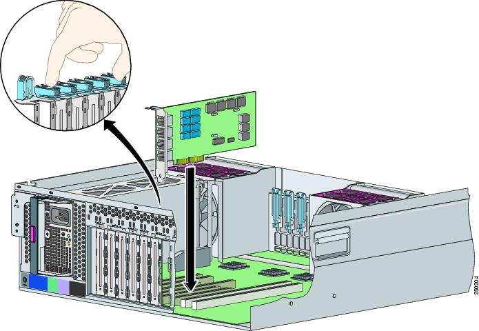
Step 9 ![]() To uninstall a card, lift the card out of the socket. To install a card, position the card so that its connector lines up over the socket on the mother board and push the card down in to the socket. Press down on the outer edge of the blue tab to lock the card in to place.
To uninstall a card, lift the card out of the socket. To install a card, position the card so that its connector lines up over the socket on the mother board and push the card down in to the socket. Press down on the outer edge of the blue tab to lock the card in to place.
Note ![]() To remove full-length expansion cards, unlock the retaining clip. To install full-length expansion cards, lock the retaining clip.
To remove full-length expansion cards, unlock the retaining clip. To install full-length expansion cards, lock the retaining clip.
Step 10 ![]() Replace the chassis cover.
Replace the chassis cover.
Step 11 ![]() Slide the server back in to the rack by pressing the server rail-release handles.
Slide the server back in to the rack by pressing the server rail-release handles.
Step 12 ![]() Reconnect the power cables to IPS 4270-20.
Reconnect the power cables to IPS 4270-20.
Step 13 ![]() Power on IPS 4270-20.
Power on IPS 4270-20.
For More Information
•![]() For an illustration of the expansion card slots, see Figure 4-7.
For an illustration of the expansion card slots, see Figure 4-7.
•![]() For an illustration of the supported interface cards, see Supported Interface Cards.
For an illustration of the supported interface cards, see Supported Interface Cards.
•![]() For the procedure for powering down IPS 4270-20 using IDM, refer to Rebooting the Sensor, for IME, refer to Rebooting the Sensor.
For the procedure for powering down IPS 4270-20 using IDM, refer to Rebooting the Sensor, for IME, refer to Rebooting the Sensor.
•![]() For the procedure for extending IPS 4270-20 from the rack, see Extending IPS 4270-20 from the Rack.
For the procedure for extending IPS 4270-20 from the rack, see Extending IPS 4270-20 from the Rack.
•![]() For more information on working in an ESD-controlled environment, see Working in an ESD Environment.
For more information on working in an ESD-controlled environment, see Working in an ESD Environment.
•![]() For the procedure for removing the chassis cover, see Removing and Replacing the Chassis Cover.
For the procedure for removing the chassis cover, see Removing and Replacing the Chassis Cover.
Installing and Removing the Power Supply
IPS 4270-20 ships with two hot-pluggable power supplies, thus providing a redundant power supply configuration. You can install or replace either power supply without powering down IPS 4270-20, as long as one power supply is active and functioning correctly.
To install and remove power supplies, follow these steps:
Step 1 ![]() Log in to the CLI.
Log in to the CLI.
Note ![]() Power supplies are hot-pluggable. You can replace a power supply while IPS 4270-20 is running, if you are replacing a redundant power supply.
Power supplies are hot-pluggable. You can replace a power supply while IPS 4270-20 is running, if you are replacing a redundant power supply.
Step 2 ![]() Prepare IPS 4270-20 to be powered off (if you only have one active, functioning power supply):
Prepare IPS 4270-20 to be powered off (if you only have one active, functioning power supply):
sensor# reset powerdown
Wait for the power down message before continuing with Step 3.
Note ![]() You can also power down IPS 4270-20 using IDM or IME.
You can also power down IPS 4270-20 using IDM or IME.
Step 3 ![]() Power off IPS 4270-20 (if you only have one active, functioning power supply).
Power off IPS 4270-20 (if you only have one active, functioning power supply).
Step 4 ![]() Remove the power cables from IPS 4270-20.
Remove the power cables from IPS 4270-20.
Step 5 ![]() Use the T-15 Torx screwdriver that shipped with IPS 4270-20 to remove the shipping screw.
Use the T-15 Torx screwdriver that shipped with IPS 4270-20 to remove the shipping screw.
The T-15 Torx screwdriver is located to the right of power supply.
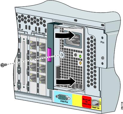
Step 6 ![]() Remove the power supply by pulling it away from the chassis.
Remove the power supply by pulling it away from the chassis.
Step 7 ![]() Install the power supply. Make sure the handle is open and slide the power supply into the bay.
Install the power supply. Make sure the handle is open and slide the power supply into the bay.
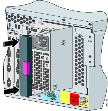
Step 8 ![]() Lock the power supply handle.
Lock the power supply handle.
Step 9 ![]() Reconnect the power cables.
Reconnect the power cables.
Be sure that the power supply indicator is green and the front panel health indicator is green.
Note ![]() Make sure the two power supplies are powered by separate AC power sources so that IPS 4270-20 is always available.
Make sure the two power supplies are powered by separate AC power sources so that IPS 4270-20 is always available.
Step 10 ![]() Power on IPS 4270-20.
Power on IPS 4270-20.
For More Information
•![]() For the procedure for powering down IPS 4270-20 using IDM, refer to Rebooting the Sensor, for IME, refer to Rebooting the Sensor.
For the procedure for powering down IPS 4270-20 using IDM, refer to Rebooting the Sensor, for IME, refer to Rebooting the Sensor.
•![]() For an illustration of the screwdriver and where it is located, see Figure 4-7.
For an illustration of the screwdriver and where it is located, see Figure 4-7.
Installing and Removing Fans
There are six fans in IPS 4270-20. IPS 4270-20 supports redundant hot-pluggable fans in a 5 + 1 configuration to provide proper airflow.
Figure 4-12 shows the fan, its connector, and its indicator.
Figure 4-12 Fan, Connector, and Indicator
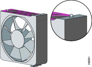
The fan indicators provide the following information:
•![]() Green—Operating normally
Green—Operating normally
•![]() Amber—Failed
Amber—Failed
•![]() Off— No power
Off— No power
To install and remove fans in IPS 4270-20, follow these steps:
Step 1 ![]() Extend the server from the rack.
Extend the server from the rack.
Step 2 ![]() Remove the chassis cover.
Remove the chassis cover.
Step 3 ![]() Identify the failed fan by locating an amber indicator on top of the failed fan or a lighted FAN X indicator on the Diagnostic Panel.
Identify the failed fan by locating an amber indicator on top of the failed fan or a lighted FAN X indicator on the Diagnostic Panel.
Step 4 ![]() Remove the failed fan by grasping the red plastic handle and pulling up.
Remove the failed fan by grasping the red plastic handle and pulling up.
Note ![]() Remove and replace one fan at a time. If IPS 4270-20 detects two failed fans, it shuts down to avoid thermal damage.
Remove and replace one fan at a time. If IPS 4270-20 detects two failed fans, it shuts down to avoid thermal damage.
Step 5 ![]() Install a new fan by positioning the fan over the slot so that the connector below the fan indicator lines up with the connection on the motherboard. Push down until the fan clicks in to place.
Install a new fan by positioning the fan over the slot so that the connector below the fan indicator lines up with the connection on the motherboard. Push down until the fan clicks in to place.
Step 6 ![]() Make sure the indicator on each fan is green.
Make sure the indicator on each fan is green.
Note ![]() If the front panel internal system health indicator is not green after you install a fan, reseat the fan.
If the front panel internal system health indicator is not green after you install a fan, reseat the fan.
Step 7 ![]() Replace the chassis cover.
Replace the chassis cover.
Step 8 ![]() Slide IPS 4270-20 back in to the rack by pressing the rail-release handles.
Slide IPS 4270-20 back in to the rack by pressing the rail-release handles.
Step 9 ![]() Power on IPS 4270-20.
Power on IPS 4270-20.
For More Information
•![]() For the fan locations, see Figure 4-9.
For the fan locations, see Figure 4-9.
•![]() For the procedure for extending IPS 4270-20 from the rack, see Extending IPS 4270-20 from the Rack.
For the procedure for extending IPS 4270-20 from the rack, see Extending IPS 4270-20 from the Rack.
•![]() For more information about the Diagnostic Panel, see Diagnostic Panel.
For more information about the Diagnostic Panel, see Diagnostic Panel.
•![]() For the procedure for removing the chassis cover, see Removing and Replacing the Chassis Cover.
For the procedure for removing the chassis cover, see Removing and Replacing the Chassis Cover.
Troubleshooting Loose Connections
Perform the following actions to troubleshoot loose connections on a sensor:
•![]() Make sure all power cords are securely connected.
Make sure all power cords are securely connected.
•![]() Make sure all cables are properly aligned and securely connected for all external and internal components.
Make sure all cables are properly aligned and securely connected for all external and internal components.
•![]() Remove and check all data and power cables for damage. Make sure no cables have bent pins or damaged connectors.
Remove and check all data and power cables for damage. Make sure no cables have bent pins or damaged connectors.
•![]() Make sure each device is properly seated.
Make sure each device is properly seated.
•![]() If a device has latches, make sure they are completely closed and locked.
If a device has latches, make sure they are completely closed and locked.
•![]() Check any interlock or interconnect indicators that indicate a component is not connected properly.
Check any interlock or interconnect indicators that indicate a component is not connected properly.
•![]() If problems continue, remove and reinstall each device, checking the connectors and sockets for bent pins or other damage.
If problems continue, remove and reinstall each device, checking the connectors and sockets for bent pins or other damage.
 Feedback