- About This Guide
- About the Firepower Management Centers
- Hardware Specifications
- Installing a Firepower Management Center
- Deploying on a Management Network
- Replacing a RAID Battery Backup Unit Assembly on the Firepower Management Center 3500
- Memory Upgrade Instructions for Firepower Management Centers
Installing a Firepower Management Center
Firepower Management Centers and Firepower managed devices are easily installed on your network as part of a larger Firepower System deployment. You install devices on network segments to inspect traffic and generate intrusion events based on the intrusion policy applied to it. This data is transmitted to a Firepower Management Center, which manages one or more devices to correlate data across your full deployment, and coordinate and respond to threats to your security.

Tip![]() You can use multiple management interfaces to improve performance or to isolate and manage traffic from two different networks. You configure the default management interface (
You can use multiple management interfaces to improve performance or to isolate and manage traffic from two different networks. You configure the default management interface (eth0) during the initial installation. You can configure additional management interfaces after installation from the user interface. For more information, see Firepower Management Center Configuration Guide.
Unpacking and Inspecting the Appliance
Tip![]() Keep the shipping container in case the server requires shipping in the future.
Keep the shipping container in case the server requires shipping in the future.

Note![]() The chassis is thoroughly inspected before shipment. If any damage occurred during transportation or any items are missing, contact your customer service representative immediately.
The chassis is thoroughly inspected before shipment. If any damage occurred during transportation or any items are missing, contact your customer service representative immediately.
To inspect the shipment, follow these steps:
Step 1![]() Remove the chassis from its cardboard container and save all packaging material.
Remove the chassis from its cardboard container and save all packaging material.
Step 2![]() Compare the shipment to the following list of components that ship with Management Centers. As you unpack the system and the associated accessories, check that your package contents are complete as follows:
Compare the shipment to the following list of components that ship with Management Centers. As you unpack the system and the associated accessories, check that your package contents are complete as follows:
- one appliance
- power cord (two power cords are included with appliances that include redundant power supplies)
- Category 5e Ethernet straight-through cable
- one rack-mounting kit
Step 3![]() Check for damage and report any discrepancies or damage to your customer service representative. Have the following information ready:
Check for damage and report any discrepancies or damage to your customer service representative. Have the following information ready:
Security Considerations
Before you install your appliance, Cisco recommends that you consider the following:
- Locate your appliance in a lockable rack within a secure location that prevents access by unauthorized personnel.
- Allow only trained and qualified personnel to install, replace, administer, or service the appliance.
- Always connect the management interface to a secure internal management network that is protected from unauthorized access.
- Identify the specific workstation IP addresses that can be allowed to access appliances. Restrict access to the appliance to only those specific hosts using Access Lists within the appliance’s system policy. For more information, see the Firepower Management Center Configuration Guide.
Identifying the Management Interfaces
You connect each appliance in your deployment to the network using the management interface. This allows the Firepower Management Center to communicate with and administer the devices it manages. Refer to the correct illustration for your appliance as you follow the installation procedure.
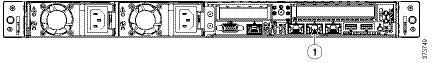
Firepower Management Center 750
The MC750 is available as a 1U appliance. The following illustration of the rear of the chassis indicates the location of the default management interface on a MC750.
|
|
|
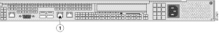
Firepower Management Center 1500
The MC1500 is available as a 1U appliance. The following illustration of the rear of the chassis indicates the location of the default management interface.
|
|
|
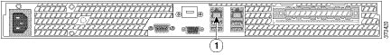
Firepower Management Center 3500
The MC3500 is available as a 1U appliance. The following illustration of the rear of the chassis indicates the location of the default management interface.
|
|
|
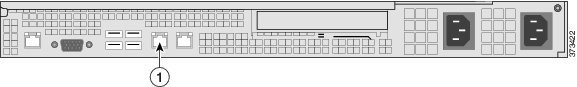
Firepower Management Center 2000 and 4000
The MC2000 and MC4000 are available as a 1U appliances. The following illustration of the rear of the chassis indicates the location of the default management interface on a MC2000 and MC4000.
|
|
|
Installing the Management Center in a Rack
You can rack-mount all Management Centers. When you install an appliance, you must also make sure that you can access its console. To access the console for initial setup, connect to the appliance in one of the following ways:
You can connect a USB keyboard and VGA monitor to a Management Center, which is useful for rack-mounted appliances connected to a keyboard, video, and mouse (KVM) switch.

Ethernet Connection to Management Interface
Configure a local computer, which must not be connected to the Internet, with the following network settings:
–![]() default gateway:
default gateway: 192.168.45.1
Using an Ethernet cable, connect the network interface on the local computer to the management interface on the appliance. Note that the management interface is preconfigured with a default IPv4 address. However, you can reconfigure the management interface with an IPv6 address as part of the setup process.
After initial setup, you can access the console in the following additional ways:
You can connect a computer to any Firepower Management Center using the physical serial port. Connect the appropriate rollover serial cable (also known as a NULL modem cable or Cisco console cable) at any time, then configure the remote management console to redirect the default VGA output to the serial port. To interact with the appliance, use terminal emulation software such as HyperTerminal or XModem. The settings for this software are 9600 baud, 8 data bits, no parity checking, 1 stop bit, and no flow control.
The serial port on a Firepower Management Center uses an RJ-45 connection.
After you connect the appropriate rollover cable to your device, redirect the console output as described in the Firepower Management Center Getting Started Guide. To locate the serial port for each appliance model, use the diagrams in Hardware Specifications.
Lights-Out Management Using Serial over LAN
The LOM feature allows you to perform a limited set of actions on a Firepower Management Center using a SOL connection. If you need to restore a LOM-capable appliance to factory defaults and do not have physical access to the appliance, you can use LOM to perform the restore process. After you connect to an appliance using LOM, you issue commands to the restore utility as if you were using a physical serial connection. For more information, see the Firepower Management Center Getting Started Guide.
Note![]() You can use Lights-Out Management on the default (
You can use Lights-Out Management on the default (eth0) management interface only.
To use LOM to restore the appliance to factory settings, do not delete network settings. Deleting the network settings also drops the LOM connection. For more information, see the Firepower Management Center Getting Started Guide.
Step 1![]() Mount the appliance in your rack using the mounting kit and its supplied instructions.
Mount the appliance in your rack using the mounting kit and its supplied instructions.
Step 2![]() Connect to the appliance using either a keyboard and monitor or Ethernet connection.
Connect to the appliance using either a keyboard and monitor or Ethernet connection.
Step 3![]() If you are using a keyboard and monitor to set up the appliance, use an Ethernet cable now to connect the management interface to a protected network segment.
If you are using a keyboard and monitor to set up the appliance, use an Ethernet cable now to connect the management interface to a protected network segment.
If you plan to perform the initial setup process by connecting a computer directly to the appliance’s management interface, you will connect the management interface to the protected network when you finish setup.
Step 4![]() Attach the power cord to the appliance and plug into a power source.
Attach the power cord to the appliance and plug into a power source.
If your appliance has redundant power supplies, attach power cords to both power supplies and plug them into separate power sources.
If you are using a direct Ethernet connection to set up the appliance, confirm that the link LED is on for both the network interface on the local computer and the management interface on the appliance. If the management interface and network interface LEDs are not lit, try using a crossover cable.
 Feedback