- About This Guide
- About the Firepower Management Centers
- Hardware Specifications
- Installing a Firepower Management Center
- Deploying on a Management Network
- Replacing a RAID Battery Backup Unit Assembly on the Firepower Management Center 3500
- Memory Upgrade Instructions for Firepower Management Centers
Cisco Firepower Management Center 750, 1500, 2000, 3500, and 4000 Hardware Installation Guide
Bias-Free Language
The documentation set for this product strives to use bias-free language. For the purposes of this documentation set, bias-free is defined as language that does not imply discrimination based on age, disability, gender, racial identity, ethnic identity, sexual orientation, socioeconomic status, and intersectionality. Exceptions may be present in the documentation due to language that is hardcoded in the user interfaces of the product software, language used based on RFP documentation, or language that is used by a referenced third-party product. Learn more about how Cisco is using Inclusive Language.
- Updated:
- March 10, 2016
Chapter: Memory Upgrade Instructions for Firepower Management Centers
Memory Upgrade Instructions for Firepower Management Centers
This section describes how to replace the memory modules that are located internally within your Cisco Firepower Management Center. You need to remove the cover from the appliance to replace these items. The document contains the following sections:
Memory Upgrade Overview
As additional software feature enhancements are introduced the minimum memory requirements are changing for the Firepower Management Centers MC750 (Rev. 1 or Rev. 2), MC1500, and MC3500 models. Appliances that do not meet the minimum memory requirement are not supported.
Table B-1 Table B-1 outlines the RAM upgrade requirements.
|
|
(prior to December 2014) |
|
(after December 2014) |
|---|---|---|---|
Upgraded Default RAM in Shipping Firepower 7000 and 8000 Series Management Centers
All Firepower MC750, MC1500, and MC3500 Management Centers will ship with additional default memory to meet the memory requirements beginning in December 2014.

Note![]() Firepower MC1500 and MC3500 Management Centers already deployed prior to December 2014 should function as intended with the default 12 GB of installed RAM. Contact Cisco regarding RAM upgrade options for your particular deployment if you encounter performance issues.
Firepower MC1500 and MC3500 Management Centers already deployed prior to December 2014 should function as intended with the default 12 GB of installed RAM. Contact Cisco regarding RAM upgrade options for your particular deployment if you encounter performance issues.
Upgrade Paths for Existing Firepower Management Centers
Table B-2 lists the memory upgrade kits that will enable customers to upgrade their existing Firepower Management Centers in order to deploy the latest software release.

|
|
|
|---|---|
Working in an ESD Environment
Electrostatic discharge (ESD) can damage equipment and impair electrical circuitry. ESD damage occurs when electronic components are improperly handled and can result in complete or intermittent failures. Always follow ESD-prevention procedures when you remove and replace components. Ensure that the chassis is electrically connected to earth ground. Wear an ESD-preventive wrist strap, ensuring that it makes good skin contact. Connect the grounding clip to an unpainted surface of the chassis frame to safely ground unwanted ESD voltages. To guard against ESD damage and shocks, the wrist strap and cord must operate properly. If no wrist strap is available, ground yourself by touching the metal part of the chassis.
Safety Warnings
This section contains important safety warnings for the installation and use of the appliance.

Warning![]() Before working on a system that has an On/Off switch, turn OFF the power and unplug the power cord. Statement 1
Before working on a system that has an On/Off switch, turn OFF the power and unplug the power cord. Statement 1
Warning![]() Only trained and qualified personnel should be allowed to install, replace, or service this equipment. Statement 1030
Only trained and qualified personnel should be allowed to install, replace, or service this equipment. Statement 1030
Warning![]() This equipment must be grounded. Never defeat the ground conductor or operate the equipment in the absence of a suitably installed ground conductor. Contact the appropriate electrical inspection authority or an electrician if you are uncertain that suitable grounding is available. Statement 1024
This equipment must be grounded. Never defeat the ground conductor or operate the equipment in the absence of a suitably installed ground conductor. Contact the appropriate electrical inspection authority or an electrician if you are uncertain that suitable grounding is available. Statement 1024
Warning![]() Do not work on the system or connect or disconnect cables during periods of lightning activity. Statement 1001
Do not work on the system or connect or disconnect cables during periods of lightning activity. Statement 1001
Warning![]() Read the installation instructions before connecting the system to the power source. Statement 1004
Read the installation instructions before connecting the system to the power source. Statement 1004
Warning![]() Ultimate disposal of this product should be handled according to all national laws and regulations. Statement 1040
Ultimate disposal of this product should be handled according to all national laws and regulations. Statement 1040
Removing the Chassis Cover
Firepower Management Centers have covers that slide off the rear of the chassis. There are slight differences between chassis models which are described in the following sections:
- Removing the Cover from Firepower Management Center 750
- Removing the Cover from Firepower Management Center 1500 and 3500
Removing the Cover from Firepower Management Center 750
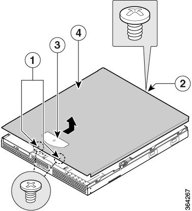
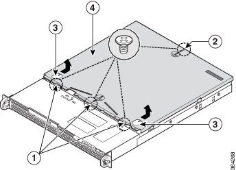
The procedure for removing the cover from a Firepower Management Center 750 differs depending on the revision of the appliance (Rev. 1 or Rev. 2). See Figure B-1 for an illustration of the MC750 Rev. 1 chassis. See Figure B-2 for an illustration of the MC750 Rev. 2 chassis.
To remove the cover from a Firepower MC750:
Note![]() A nonskid surface or a stop behind the MC750 (Rev. 1 or Rev. 2) may be needed to prevent the device from sliding on your work surface.
A nonskid surface or a stop behind the MC750 (Rev. 1 or Rev. 2) may be needed to prevent the device from sliding on your work surface.
Step 1![]() Observe the ESD precautions described in Working in an ESD Environment and the safety precautions described in Safety Warnings.
Observe the ESD precautions described in Working in an ESD Environment and the safety precautions described in Safety Warnings.
Step 2![]() Remove the security screws from the front of the chassis:
Remove the security screws from the front of the chassis:
- For Rev. 1, there are two (2) screws (see “1” in Figure B-1).
- For Rev. 2, there are three (3) screws (see “1” in Figure B-2).
Step 3![]() Remove the security screw from the rear of the chassis. See “2” in Figure B-1 and Figure B-2.
Remove the security screw from the rear of the chassis. See “2” in Figure B-1 and Figure B-2.
Step 4![]() Slide the cover towards the rear by pushing on the blue grip points on the chassis cover:
Slide the cover towards the rear by pushing on the blue grip points on the chassis cover:
- For Rev. 1, there is one (1) grip point (see “3” in Figure B-1).
- For Rev. 2, there are two (2) grip points (see “3” in Figure B-2).
Step 5![]() Lift the over off and set aside.
Lift the over off and set aside.
- Remove the processor air duct as described in the “Removing the Processor Air Duct from Firepower Management Center 750” section.
Figure B-1 Removing the Cover from a MC750 Rev. 1
|
|
|
||
|
|
|
Figure B-2 Removing the Cover from a MC750 Rev. 2
|
|
|
||
|
|
|
Removing the Cover from Firepower Management Center 1500 and 3500
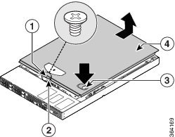
The MC1500 and MC3500 Management Centers share some of the same form factors. The following procedure can apply to either device.
To remove the cover from a Firepower MC1500 or MC3500:
Note![]() A nonskid surface or a stop behind the MC1500 or MC3500 may be needed to prevent the device from sliding on your work surface.
A nonskid surface or a stop behind the MC1500 or MC3500 may be needed to prevent the device from sliding on your work surface.
Step 1![]() Observe the ESD precautions described in Working in an ESD Environment and the safety precautions described in Safety Warnings.
Observe the ESD precautions described in Working in an ESD Environment and the safety precautions described in Safety Warnings.
Step 2![]() Remove the security screw if it is installed (see “1” in Figure B-3).
Remove the security screw if it is installed (see “1” in Figure B-3).
Step 3![]() Cut the warranty label on the unit if it is intact.
Cut the warranty label on the unit if it is intact.
Step 4![]() While holding in the blue button on the top of the chassis (see “3” in Figure B-3), slide the top cover back until it stops (see “4” in Figure B-3).
While holding in the blue button on the top of the chassis (see “3” in Figure B-3), slide the top cover back until it stops (see “4” in Figure B-3).
- On the MC1500, the button is on the left.
- On the MC3500, the button is on the right as shown in Figure B-3.
Step 5![]() Insert your finger in the notch (see “2” in Figure B-3) and lift the cover upward to remove it.
Insert your finger in the notch (see “2” in Figure B-3) and lift the cover upward to remove it.
- Remove the processor air duct as described in the “Removing the Processor Air Duct from Firepower Management Center 1500 and 3500” section.
Figure B-3 Removing the Cover from a MC1500 or MC3500
|
|
|
||
|
|
|
Removing the Processor Air Duct
Firepower Management Centers operate with processor air ducts in place. The air ducts are required for proper airflow within the chassis. It is necessary to remove the air ducts to gain full access to the DIMM sockets on the chassis. There are some differences between chassis models which are described in the following sections:
- Removing the Processor Air Duct from Firepower Management Center 750
- Removing the Processor Air Duct from Firepower Management Center 1500 and 3500
Removing the Processor Air Duct from Firepower Management Center 750
The procedure for removing the air duct from a Firepower MC750 differs depending on the revision of the appliance (Rev. 1 or Rev. 2). See Figure B-4 for an illustration of the MC750 Rev. 1 chassis. See Figure B-5 for an illustration of the MC750 Rev. 2 chassis.
To remove the processor air duct from a Firepower MC750:
Step 1![]() Observe the ESD precautions described in Working in an ESD Environment and the safety precautions described in Safety Warnings.
Observe the ESD precautions described in Working in an ESD Environment and the safety precautions described in Safety Warnings.
Step 2![]() Lift the processor air duct from its location behind the system cooling fans:
Lift the processor air duct from its location behind the system cooling fans:
- For Rev. 1 chassis see “1” in Figure B-4)
- For Rev. 2 chassis see “1” in Figure B-5).
Step 3![]() Set the air duct aside.
Set the air duct aside.
- Remove the Firepower MC750 DIMMs as described in the “Replacing the DIMMs” section.
Figure B-4 Removing the Processor Air Duct from a MC750 Rev. 1
|
|
|
Figure B-5 Removing the Processor Air Duct from a MC750 Rev. 2
|
|
|
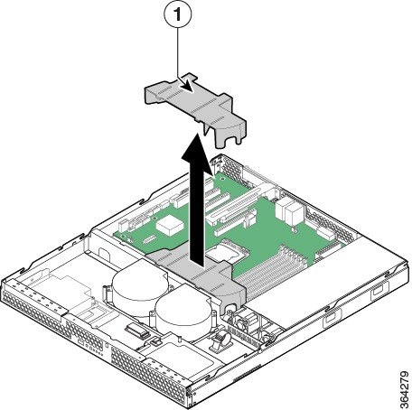
Removing the Processor Air Duct from Firepower Management Center 1500 and 3500
The Firepower MC1500 and MC3500 share some of the same form factors. The following procedure can apply to either device.
Note![]() Before the processor air duct can be removed from a MC1500 and MC3500, the adjacent PCI Riser Assembly must first be removed.
Before the processor air duct can be removed from a MC1500 and MC3500, the adjacent PCI Riser Assembly must first be removed.
To remove the processor air duct from a Firepower MC1500 or MC3500:
Step 1![]() Observe the ESD precautions described in Working in an ESD Environment and the safety precautions described in Safety Warnings.
Observe the ESD precautions described in Working in an ESD Environment and the safety precautions described in Safety Warnings.
Step 2![]() Disconnect any cables attached to any add-in cards.
Disconnect any cables attached to any add-in cards.
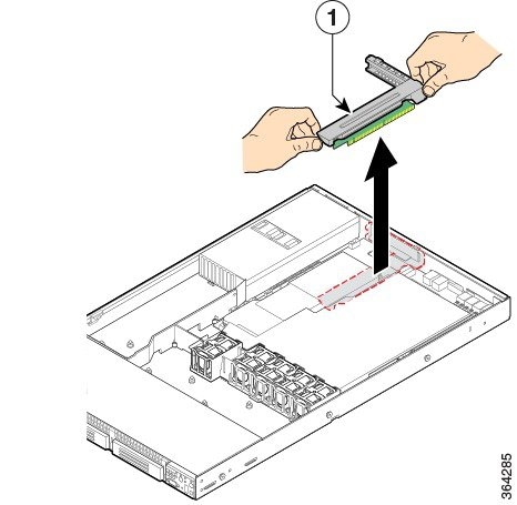
Step 3![]() Grasp both riser latches with thumb and forefinger and pull up to release the riser assembly.
Grasp both riser latches with thumb and forefinger and pull up to release the riser assembly.
Step 4![]() Lift riser assembly straight up (see “1” in Figure B-6).
Lift riser assembly straight up (see “1” in Figure B-6).
Figure B-6 Removing the PCI Riser Assembly from a MC1500 or MC3500
|
|
|
Step 5![]() Set the riser assembly upside down to avoid damage to the riser card connector.
Set the riser assembly upside down to avoid damage to the riser card connector.
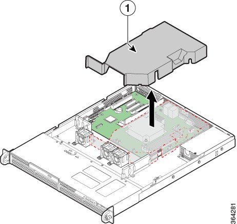
Step 6![]() Lift the processor air duct from its location over the two processor sockets (see “1” in Figure B-7).
Lift the processor air duct from its location over the two processor sockets (see “1” in Figure B-7).
Figure B-7 Removing the Processor Air Duct from a MC1500 or MC3500

|
|
|
- Remove the MC1500 or MC3500 DIMMs as described in the “Replacing the DIMMs” section.
Replacing the DIMMs
To ensure the best appliance performance, it is important that you are familiar with memory requirement guidelines and population rules before you install or replace memory modules. See Table B-1 in Memory Upgrade Overview for a reminder of the default memory configurations that shipped with Firepower Management Centers prior to the release of Firepower System 5.4.
Table B-3 below outlines the new memory requirements to run Firepower System 5.4 and greater. Appliances that do not meet the minimum memory requirement are not supported.
|
|
|
|
|---|---|---|
DIMM Location and Orientation
On the Firepower MC750 (Rev. 1 or Rev. 2), MC1500, and MC3500, the DIMM connectors are located on the system board and are identified by silkscreen labels. You can also refer to the Quick Reference Label on the inside of the chassis cover to assist in locating components.

Tip![]() Please note that only blue DIMM connectors are populated with modules.
Please note that only blue DIMM connectors are populated with modules.
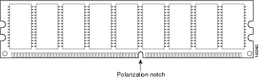
DIMMs have a polarization notch on the mating edge to prevent incorrect insertion. Figure B-8 shows the polarization notch on a DIMM.
Figure B-8 DIMM Showing Polarization Notch
|
|
|
Locating DIMMs in Firepower Management Centers
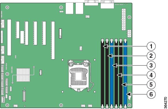
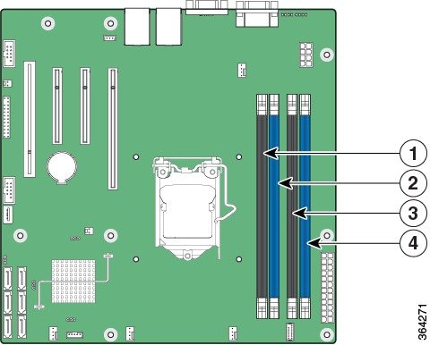
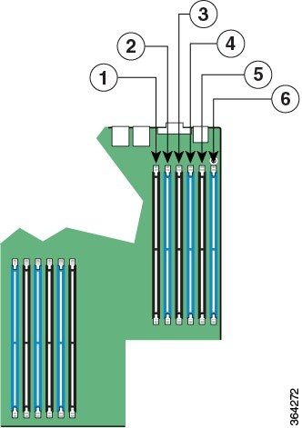
Use the following figures to identify the correct DIMM connectors for your memory upgrade requirements identified in Table B-3 . The silkscreen on the system board also displays the DIMM labels starting from the center of the board.
- Refer to Figure B-9 for the location of the DIMM connectors on the MC750 (Rev. 1).
- Refer to Figure B-10 for the location of the DIMM connectors on the MC750 (Rev. 2).
- Refer to Figure B-11 for the location of the DIMM connectors on the MC1500 and MC3500.
Figure B-9 Memory Configuration and Population Order for the MC750 Rev. 1
|
|
|
||
|
|
|
||
|
|
|
Figure B-10 Memory Configuration and Population Order for the MC750 Rev. 2
|
|
|
||
|
|
|
Figure B-11 Memory Configuration and Population Order for the MC1500 and MC3500
|
|
|
||
|
|
|
||
|
|
|
Removing DIMMs from Firepower Management Centers
Firepower MC750 (Rev. 1 and Rev. 2) Management Centers have 4GB of system memory installed on the system board. You must remove all installed DIMMs and replace them with the modules in your upgrade kit to complete the system upgrade to 8GB of RAM.
Firepower MC1500 and MC3500 Management Centers have 12GB of system memory installed on the system board. You must remove all installed DIMMs and replace them with the modules in your upgrade kit to complete the system upgrade to 48GB of RAM.
To remove DIMMs from the system board:
Step 1![]() Observe the ESD precautions described in Working in an ESD Environment and the safety precautions described in Safety Warnings.
Observe the ESD precautions described in Working in an ESD Environment and the safety precautions described in Safety Warnings.
Step 2![]() Locate the DIMMs on the system board. See Figure B-9, Figure B-10, or Figure B-11 depending on your FireSIGHT Management Center model, for the location of the DIMM connectors.
Locate the DIMMs on the system board. See Figure B-9, Figure B-10, or Figure B-11 depending on your FireSIGHT Management Center model, for the location of the DIMM connectors.
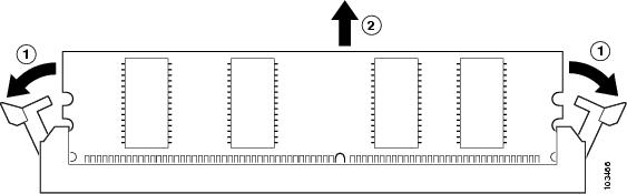
Step 3![]() Pull the latches away from the DIMM at both ends; this lifts the DIMM slightly. Then lift the DIMM out of the connector. See Figure B-12.
Pull the latches away from the DIMM at both ends; this lifts the DIMM slightly. Then lift the DIMM out of the connector. See Figure B-12.
|
|
|
- Place any removed DIMMs in anti-static bags to protect them from ESD damage. Observe applicable Federal, state, and local regulations regarding the disposal of these components.
- Install the new DIMMs from your memory upgrade kit in your FireSIGHT Management Center as described in the “Installing DIMMs in Firepower Management Centers” section.
Installing DIMMs in Firepower Management Centers
To install a DIMM in a Firepower MC750 (Rev. 1 and 2), MC1500, and MC3500:
Step 1![]() Locate the DIMMs on the system board:
Locate the DIMMs on the system board:
- Refer to Figure B-9 for the location of the DIMM connectors on the MC750 (Rev. 1).
- Refer to Figure B-10 for the location of the DIMM connectors on the MC750 (Rev. 2).
- Refer to Figure B-11 for the location of the DIMM connectors on the MC1500 and MC3500.
- Refer to Table B-3 for memory upgrade configurations for each Management Center model.
Step 2![]() Make sure that both latches on the DIMM connector are in the open position.
Make sure that both latches on the DIMM connector are in the open position.
Step 3![]() Orient the DIMM so that the polarization notch lines up with the polarization key on the connector. See Figure B-8.
Orient the DIMM so that the polarization notch lines up with the polarization key on the connector. See Figure B-8.
Step 4![]() Align the DIMM carefully into the connector.
Align the DIMM carefully into the connector.
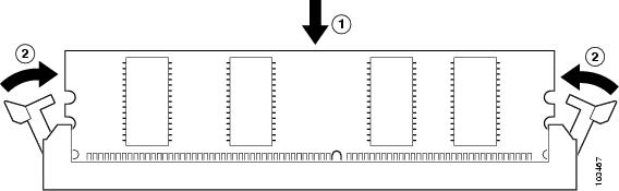
Step 5![]() Carefully and firmly press the DIMM into the connector until the latches close onto the DIMM. Make sure that both latches rotate to the closed position against the DIMM. See Figure B-13.
Carefully and firmly press the DIMM into the connector until the latches close onto the DIMM. Make sure that both latches rotate to the closed position against the DIMM. See Figure B-13.
|
|
|
- Replace the processor air duct in your Firepower Management Center as described in the “Installing the Processor Air Duct” section.
Installing the Processor Air Duct
Firepower Management Centers must operate with processor air ducts in place. The air ducts are required for proper airflow within the chassis. It is necessary to reinstall the air ducts after any maintenance procedures. There are some differences between chassis models which are described in the following sections:
- Installing the Processor Air Duct on Firepower Management Center 750
- Installing the Processor Air Duct on Firepower Management Center 1500 and 3500
Installing the Processor Air Duct on Firepower Management Center 750
The procedure for installing the processor air duct on a Firepower MC750 differs depending on the revision of the appliance (Rev. 1 or Rev. 2). See Figure B-14 for an illustration of the Firepower MC750 Rev. 1 chassis. See Figure B-15 for an illustration of the Firepower MC750 Rev. 2 chassis.
To install the air duct on a Firepower MC750:
Step 1![]() Observe the ESD precautions described in Working in an ESD Environment and the safety precautions described in Safety Warnings.
Observe the ESD precautions described in Working in an ESD Environment and the safety precautions described in Safety Warnings.
Step 2![]() Lower the processor air duct into place.
Lower the processor air duct into place.
- For Rev. 1 chassis, insert the two hooks at the front of the processor air duct into the corresponding slots on the bracket behind the two system cooling fans (see “1” in Figure B-14).
- For Rev. 2 chassis, insert the two hooks at the front of the processor air duct into the corresponding slots on the bracket behind the two system cooling fans. Use caution not to pinch or disengage cables that may be near or under the air duct (see “1” in Figure B-15).
- Install the chassis cover as described in the “Installing the Cover on Firepower Management Center 750” section.
Figure B-14 Installing the Processor Air Duct on a MC750 Rev. 1

|
|
|
Figure B-15 Installing the Processor Air Duct on a MC750 Rev. 2

|
|
|
Installing the Processor Air Duct on Firepower Management Center 1500 and 3500
The Firepower MC1500 and MC3500 Management Centers share some of the same form factors. The following procedure can apply to either device.
Note![]() After the processor air duct is installed from a Firepower MC1500 and MC3500, the adjacent PCI Riser Assembly must be installed.
After the processor air duct is installed from a Firepower MC1500 and MC3500, the adjacent PCI Riser Assembly must be installed.
To install the processor air duct on a Firepower MC1500 or MC3500:
Step 1![]() Observe the ESD precautions described in Working in an ESD Environment and the safety precautions described in Safety Warnings.
Observe the ESD precautions described in Working in an ESD Environment and the safety precautions described in Safety Warnings.
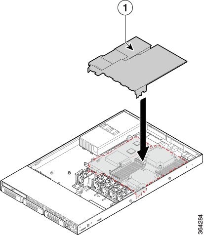
Step 2![]() Place the processor air duct over the processor socket. The front edge of the air duct should align correctly with the notches on the fan module. Use caution not to pinch or disengage cables that may be near or under the air duct. See “1” in Figure B-16.
Place the processor air duct over the processor socket. The front edge of the air duct should align correctly with the notches on the fan module. Use caution not to pinch or disengage cables that may be near or under the air duct. See “1” in Figure B-16.
Figure B-16 Installing the Processor Air Duct on a MC1500 or MC3500
|
|
|
Step 3![]() Lower the PCI riser assembly into place. Align the two hooks in the riser assembly with the matching slots at the back of chassis (see “1” in Figure B-17).
Lower the PCI riser assembly into place. Align the two hooks in the riser assembly with the matching slots at the back of chassis (see “1” in Figure B-17).
Step 4![]() Press down uniformly until the two hooks on the rear of the PCI riser assembly engage the chassis back panel slots. The riser cards will seat into the matching sockets on the system board.
Press down uniformly until the two hooks on the rear of the PCI riser assembly engage the chassis back panel slots. The riser cards will seat into the matching sockets on the system board.
Figure B-17 Installing the PCI Riser Assembly on a MC1500 or MC3500

|
|
|
- Reconnect any cables attached to any add-in cards.
- Install the chassis cover as described in the “Installing the Cover on Firepower Management Center 1500 and 3500” section.
Installing the Chassis Cover
FireSIGHT Management Centers have covers that slide on from the rear of the chassis. There are slight differences between chassis models which are described in the following sections:
- Installing the Cover on Firepower Management Center 750
- Installing the Cover on Firepower Management Center 1500 and 3500
Installing the Cover on Firepower Management Center 750
To install the cover on a Firepower MC750:
Note![]() A nonskid surface or a stop behind the MC750 may be needed to prevent the device from sliding on your work surface.
A nonskid surface or a stop behind the MC750 may be needed to prevent the device from sliding on your work surface.
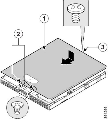
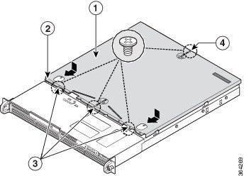
Step 1![]() Place the cover onto the chassis and slide forward (see “1” in Figure B-18 and Figure B-19).
Place the cover onto the chassis and slide forward (see “1” in Figure B-18 and Figure B-19).
Step 2![]() Install the security screws on the front of the chassis:
Install the security screws on the front of the chassis:
- For Rev. 1, there are two (2) screws (see “1” in Figure B-18).
- For Rev. 2, there are three (3) screws (see “1” in Figure B-19).
Step 3![]() Install the security screw on the rear of the chassis. See “3” in Figure B-18 and “4” in Figure B-19.
Install the security screw on the rear of the chassis. See “3” in Figure B-18 and “4” in Figure B-19.
Figure B-18 Installing the Cover on a MC750 Rev. 1
|
|
|
||
|
|
|
Figure B-19 Installing the Cover on a MC750 Rev. 2
|
|
|
||
|
|
|
Installing the Cover on Firepower Management Center 1500 and 3500
To install the cover on a Firepower MC1500 or MC3500:
Note![]() A nonskid surface or a stop behind the MC1500 or MC3500 may be needed to prevent the device from sliding on your work surface.
A nonskid surface or a stop behind the MC1500 or MC3500 may be needed to prevent the device from sliding on your work surface.
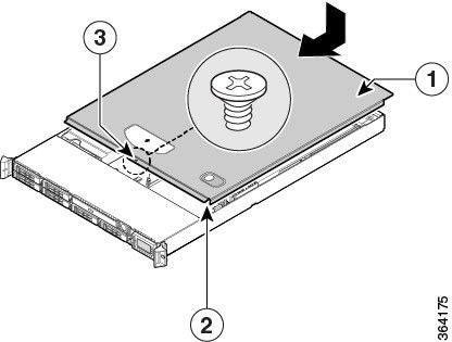
Step 1![]() Place the cover over the device as shown in Figure B-20 so that the side edges of the cover sit just inside the chassis sidewalls.
Place the cover over the device as shown in Figure B-20 so that the side edges of the cover sit just inside the chassis sidewalls.
Step 2![]() Slide the cover forward to engage the recessed edge of the cover with the front of the chassis (see “2” in Figure B-20). Make sure the cover latch clicks into place.
Slide the cover forward to engage the recessed edge of the cover with the front of the chassis (see “2” in Figure B-20). Make sure the cover latch clicks into place.
Step 3![]() Insert the security screw at the center of the top cover (see “3” in Figure B-20).
Insert the security screw at the center of the top cover (see “3” in Figure B-20).
Figure B-20 Installing the Cover on a MC1500 and MC3500
|
|
|
||
|
|
|
 Feedback