- About This Guide
- About the Firepower 7000 Series
- Hardware Specifications
- Installing a Firepower 7000 Series Managed Device
- Using the LCD Panel on a Firepower Device
- Deploying on a Management Network
- Deploying Firepower Managed Devices
- Power Requirements for Firepower 7000 Series Devices
- Using SFP Transceivers in Firepower 71x5 and AMP7150 Devices
Installing a Firepower 7000 Series Managed Device
Firepower System appliances are easily installed on your network as part of a larger Firepower System deployment. You install devices on network segments to inspect traffic and generate intrusion events based on the intrusion policy applied to it. This data is transmitted to a Firepower Management Center, which manages one or more devices to correlate data across your full deployment, and coordinate and respond to threats to your security.

Tip You can use multiple management interfaces to improve performance or to isolate and manage traffic from two different networks. You configure the default management interface (eth0) during the initial installation. You can configure additional management interfaces after installation from the user interface. For more information, see Firepower Management Center Configuration Guide.
You can pre-configure multiple appliances at one location to be used in different deployment locations. For guidance on pre-configuring, see the Firepower 7000 Series Getting Started Guide .
Unpacking and Inspecting the Appliance
Tip Keep the shipping container in case the server requires shipping in the future.

Note The chassis is thoroughly inspected before shipment. If any damage occurred during transportation or any items are missing, contact your customer service representative immediately.
To inspect the shipment, follow these steps:
Step 1 Remove the chassis from its cardboard container and save all packaging material.
Step 2 Compare the shipment to the following list of components that ship with Firepower 7000 Series devices. As you unpack the system and the associated accessories, check that your package contents are complete as follows:
- one appliance
- power cord (two power cords are included with appliances that include redundant power supplies)
- Category 5e Ethernet straight-through cables: two for a Firepower device
- one rack-mounting kit (required tray and rack-mounting kit available separately for the Firepower 7010, 7020, 7030, and 7050)
Step 3 Check for damage and report any discrepancies or damage to your customer service representative. Have the following information ready:
Security Considerations
Before you install your appliance, Cisco recommends that you consider the following:
- Locate your appliance in a lockable rack within a secure location that prevents access by unauthorized personnel.
- Allow only trained and qualified personnel to install, replace, administer, or service the appliance.
- Always connect the management interface to a secure internal management network that is protected from unauthorized access.
- Identify the specific workstation IP addresses that can be allowed to access appliances. Restrict access to the appliance to only those specific hosts using Access Lists within the appliance’s system policy. For more information, see the Firepower Management Center Configuration Guide .
Identifying the Management Interfaces
You connect each appliance in your deployment to the network using the management interface. This allows the Firepower Management Center to communicate with and administer the devices it manages. Refer to the correct illustration for your appliance as you follow the installation procedure.
Firepower 7000 Series
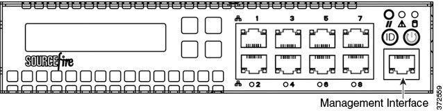
The Firepower 7010, 7020, 7030, and 7050 are 1U appliances that are one-half the width of the chassis tray. The following illustration of the front of the chassis indicates the default management interface.
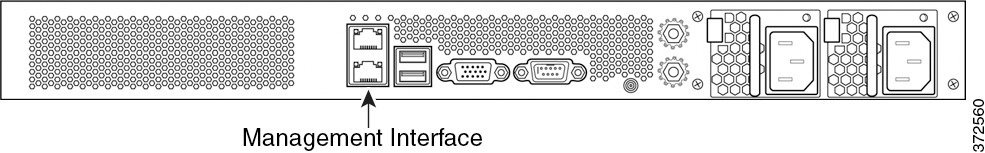
The Firepower 7110/7120, the 7115/7125, and the AMP7150 are available as 1U appliances. The following illustration of the rear of the chassis indicates the location of the default management interface.
Identifying the Sensing Interfaces
Firepower devices connect to network segments using sensing interfaces. The number of segments each device can monitor depends on the number of sensing interfaces on the device and the type of connection (passive, inline, routed, or switched) that you want to use on the network segment.
The following sections describe the sensing interfaces for each Firepower device:
- To locate the sensing interfaces on the 7000 Series, see Firepower 7000 Series.
For information on connection types, see Understanding Sensing Interfaces.
Firepower 7000 Series
The 7000 Series is available in the following configurations:
- 1U device one-half the width of the rack tray with eight copper interfaces, each with configurable bypass capability.
- 1U device with either eight copper interfaces or eight fiber interfaces, each with configurable bypass capability
- 1U device with four copper interfaces with configurable bypass capability and eight small form-factor pluggable (SFP) ports without bypass capability
Firepower 7010, 7020, 7030, and 7050
The Firepower 7010, 7020, 7030, and 7050 are delivered with eight copper port sensing interfaces, each with configurable bypass capability. The following illustration of the front of the chassis indicates the location of the sensing interfaces.
Figure 3-1 Eight Port 1000BASE-T Copper Configurable Bypass Interfaces
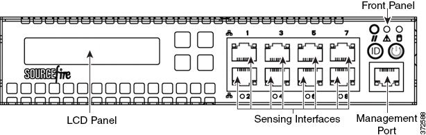
You can use these connections to passively monitor up to eight separate network segments. You can also use paired interfaces in inline or inline with bypass mode to deploy the device as an intrusion prevention system on up to four networks.
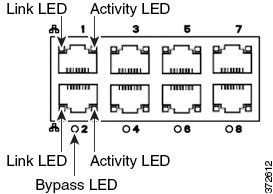
If you want to take advantage of the device’s automatic bypass capability, you must connect two interfaces vertically (interfaces 1 and 2, 3 and 4, 5 and 6, or 7 and 8) to a network segment. Automatic bypass capability allows traffic to flow even if the device fails or loses power. After you cable the interfaces, you use the web interface to configure a pair of interfaces as an inline set and enable bypass mode on the inline set.
Firepower 7110 and 7120
The Firepower 7110 and 7120 are delivered with eight copper port sensing interfaces, or eight fiber port sensing interfaces, each with configurable bypass capability. The following illustration of the front of the chassis indicates the location of the sensing interfaces.
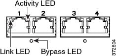
Figure 3-2 Firepower 7110 and 7120 Copper Interfaces

Figure 3-3 Eight-Port 1000BASE-T Copper Interfaces
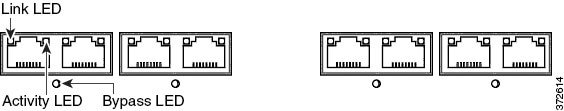
You can use these connections to passively monitor up to eight separate network segments. You can also use paired interfaces in inline or inline with bypass mode to deploy the device as an intrusion prevention system on up to four networks.
If you want to take advantage of the device’s automatic bypass capability, you must connect either the two interfaces on the left or the two interfaces on the right to a network segment. Automatic bypass capability allows traffic to flow even if the device fails or loses power. After you cable the interfaces, you use the web interface to configure a pair of interfaces as an inline set and enable bypass mode on the inline set.
Figure 3-4 Firepower 7110 and 7120 Fiber Interfaces
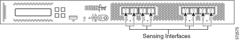
Figure 3-5 Eight-Port 1000BASE-SX Fiber Configurable Bypass
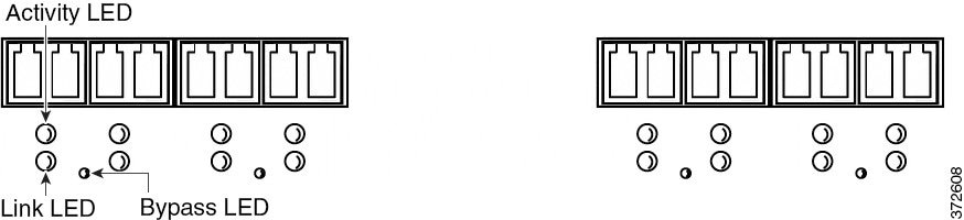
The eight-port 1000BASE-SX fiber configurable bypass configuration uses LC-type (Local Connector) optical transceivers.
You can use these connections to passively monitor up to eight separate network segments. You can also use paired interfaces in inline or inline with bypass mode to deploy the device as an intrusion prevention system on up to four networks.
Tip For best performance, use the interface sets consecutively. If you skip any interfaces, you may experience degraded performance.
If you want to take advantage of the device’s automatic bypass capability, you must connect either the two interfaces on the left or the two interfaces on the right to a network segment. Automatic bypass capability allows traffic to flow even if the device fails or loses power. After you cable the interfaces, you use the web interface to configure a pair of interfaces as an inline set and enable bypass mode on the inline set.
Firepower 7115, 7125, and AMP7150
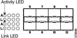
The Firepower 7115, 7125, and AMP7150 devices are delivered with four-port copper interfaces with configurable bypass capability, and eight hot-swappable small form-factor pluggable (SFP) ports without bypass capability. The following illustration of the front of the chassis indicates the location of the sensing interfaces.
Figure 3-6 Firepower 7115, 7125, and AMP7150 Copper and SFP Interfaces
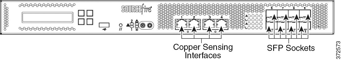
Figure 3-7 Four 1000BASE-T Copper Interfaces
You can use the copper interfaces to passively monitor up to four separate network segments. You can also use paired interfaces in inline or inline with bypass mode to deploy the device as an intrusion prevention system on up to two networks.
If you want to take advantage of the device’s automatic bypass capability, you must connect either the two interfaces on the left or the two interfaces on the right to a network segment. Automatic bypass capability allows traffic to flow even if the device fails or loses power. After you cable the interfaces, you use the web interface to configure a pair of interfaces as an inline set and enable bypass mode on the inline set.
When you install Cisco SFP transceivers into the SFP sockets, you can passively monitor up to eight separate network segments. You can also use paired interfaces in inline, non-bypass mode to deploy the device as an intrusion detection system on up to four networks.
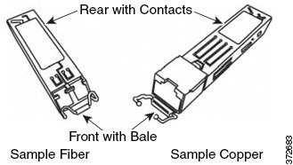
Cisco SFP transceivers are available in 1G copper, 1G short range fiber, or 1G long range fiber, and are hot-swappable. You can use any combination of copper or fiber transceivers in your device in either passive or inline configuration. Note that SFP transceivers do not have bypass capability and should not be used in intrusion prevention deployments. To ensure compatibility, use only SFP transceivers available from Cisco. See Using SFP Transceivers in Firepower 71x5 and AMP7150 Devices for more information.
Figure 3-8 Sample SFP Transceivers
Installing the Firepower Device in a Rack
You can rack-mount all Firepower devices (with purchase of a 1U mounting kit for Firepower 7010, 7020, 7030, and 7050). When you install an appliance, you must also make sure that you can access its console. To access the console for initial setup, connect to the appliance in one of the following ways:
You can connect a USB keyboard and VGA monitor to a Firepower device, which is useful for rack-mounted appliances connected to a keyboard, video, and mouse (KVM) switch.

Caution Do not use a KVM console with USB mass storage to access the appliance for the initial setup because the appliance may attempt to use the mass storage device as a boot device.
Ethernet Connection to Management Interface
Configure a local computer, which must not be connected to the Internet, with the following network settings:
– default gateway:
192.168.45.1
Using an Ethernet cable, connect the network interface on the local computer to the management interface on the appliance. Note that the management interface is preconfigured with a default IPv4 address. However, you can reconfigure the management interface with an IPv6 address as part of the setup process.
After initial setup, you can access the console in the following additional ways:
You can connect a computer to any Firepower device using the physical serial port. Connect the appropriate rollover serial cable (also known as a NULL modem cable or Cisco console cable) at any time, then configure the remote management console to redirect the default VGA output to the serial port. To interact with the appliance, use terminal emulation software such as HyperTerminal or XModem. The settings for this software are 9600 baud, 8 data bits, no parity checking, 1 stop bit, and no flow control.
A serial port may have an RJ-45 connection or a DB-9 connection, depending on the appliance. See the following table for connectors by appliance.
After you connect the appropriate rollover cable to your device, redirect the console output as described in the Firepower 7000 Series Getting Started Guide . To locate the serial port for each appliance model, use the diagrams in Hardware Specifications.
Lights-Out Management Using Serial over LAN
The LOM feature allows you to perform a limited set of actions on a Firepower Management Center or Firepower device using a SOL connection. If you need to restore a LOM-capable appliance to factory defaults and do not have physical access to the appliance, you can use LOM to perform the restore process. After you connect to an appliance using LOM, you issue commands to the restore utility as if you were using a physical serial connection. For more information, see the Firepower 7000 Series Getting Started Guide .
Note You can use Lights-Out Management on the default (eth0) management interface only.
To use LOM to restore the appliance to factory settings, do not delete network settings. Deleting the network settings also drops the LOM connection. For more information, see the Firepower 7000 Series Getting Started Guide .
Step 1 Mount the appliance in your rack using the mounting kit and its supplied instructions.
Step 2 Connect to the appliance using either a keyboard and monitor or Ethernet connection.
Step 3 If you are using a keyboard and monitor to set up the appliance, use an Ethernet cable now to connect the management interface to a protected network segment.
If you plan to perform the initial setup process by connecting a computer directly to the appliance’s management interface, you will connect the management interface to the protected network when you finish setup.
Step 4 For a Firepower device, connect the sensing interfaces to the network segments you want to analyze using the appropriate cables for your interfaces:
- Copper Sensing Interfaces: If your device includes copper sensing interfaces, make sure you use the appropriate cables to connect them to your network; see Cabling Inline Deployments on Copper Interfaces.
- Fiber Adapter Card: For devices with a fiber adapter card, connect the LC connectors on the optional multimode fiber cable to two ports on the adapter card in any order. Connect the SC plug to the network segment you want to analyze.
- Fiber Tap: If you are deploying the device with an optional fiber optic tap, connect the SC plug on the optional multimode fiber cable to the “analyzer” port on the tap. Connect the tap to the network segment you want to analyze.
- Copper Tap: If you are deploying the device with an optional copper tap, connect the A and B ports on the left of the tap to the network segment you want to analyze. Connect the A and B ports on the right of the tap (the “analyzer” ports) to two copper ports on the adapter card.
For more information about options for deploying the managed device, see Deploying Firepower Managed Devices.
Note that if you are deploying a device with bypass interfaces, you are taking advantage of your device’s ability to maintain network connectivity even if the device fails. See Testing an Inline Bypass Interface Installation for information on installation and latency testing.
Step 5 Attach the power cord to the appliance and plug into a power source.
If your appliance has redundant power supplies, attach power cords to both power supplies and plug them into separate power sources.
If you are using a direct Ethernet connection to set up the appliance, confirm that the link LED is on for both the network interface on the local computer and the management interface on the appliance. If the management interface and network interface LEDs are not lit, try using a crossover cable. For more information, see Cabling Inline Deployments on Copper Interfaces.
- Complete the setup process that allows the new appliance to communicate on your trusted management network; see the Firepower 7000 Series Getting Started Guide .
- If you are deploying a device with bypass interfaces, test that you properly installed these devices; see Testing an Inline Bypass Interface Installation.
Testing an Inline Bypass Interface Installation
Managed devices with bypass interfaces provide the ability to maintain network connectivity even when the device is powered off or inoperative. It is important to ensure that you properly install these devices and quantify any latency introduced by their installation.
Note Your switch’s spanning tree discovery protocol can cause a 30-second traffic delay. Cisco recommends that you disable the spanning tree during the following procedure.
The following procedure, applicable only to copper interfaces, describes how to test the installation and ping latency of an inline bypass interface. You will need to connect to the network to run ping tests and connect to the managed device console.
-
Ensure that the interface set type for the Firepower device is configured for inline bypass mode.
See Configuring Inline Sets in the Firepower Management Center Configuration Guide for instructions on configuring an interface set for inline bypass mode.
To test a device with inline bypass interface installation:
Step 1 Set all interfaces on the switch, the firewall, and the device sensing interfaces to auto-negotiate.
Note Firepower System devices require auto-negotiate when using auto-MDIX on the device.
Step 2 Power off the device and disconnect all network cables.
Reconnect the device and ensure you have the proper network connections. Check cabling instructions for crossover versus straight-through from the device to the switches and firewalls, see Cabling Inline Deployments on Copper Interfaces.
Step 3 With the device powered off, ensure that you can ping from the firewall through the device to the switch.
If the ping fails, correct the network cabling.
Step 4 Run a continuous ping until you complete step 9 .
Step 5 Power the device back on.
Step 6 Using your keyboard/monitor or serial connection, log into the device using an account with Administrator privileges. The password is the same as the password for the device’s web interface.
The prompt for the device appears.
Step 7 Shut down the device by typing
system shutdown
.
You can also shut down the device using its web interface; see the Managing Devices chapter in the Firepower Management Center Configuration Guide . As most devices power off, they emit an audible click sound. The click is the sound of relays switching and the device going into hardware bypass.
Verify that your ping traffic resumes.
Step 9 Power the device back on, and verify that your ping traffic continues to pass.
Step 10 For Firepower devices that support tap mode, you can test and record ping latency results under the following sets of conditions:
Ensure that the latency periods are acceptable for your installation. For information on resolving excessive latency problems, see Configuring Packet Latency Thresholding and Understanding Rule Latency Thresholding in the Firepower Management Center Configuration Guide .
 Feedback