Logical Devices

About Logical Devices

A logical device lets you run one application instance (either ASA or Firepower Threat Defense) and also one optional decorator application (Radware DefensePro) to form a service chain .

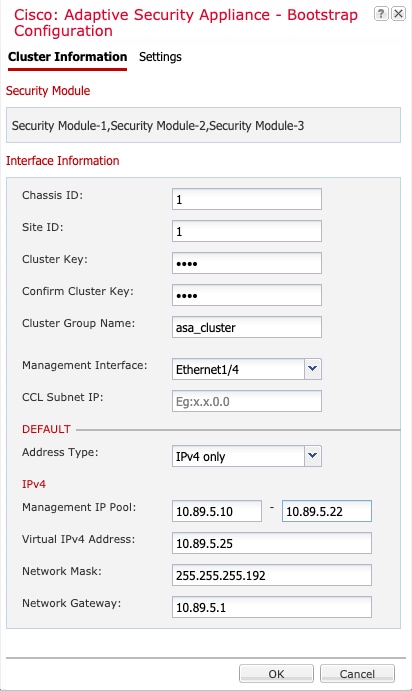
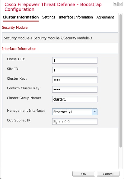
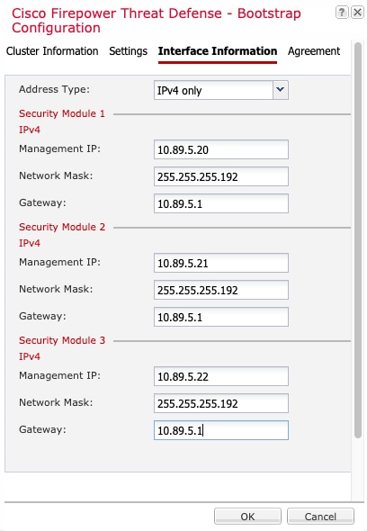
When you add a logical device, you also define the application instance type and version, assign interfaces, and configure bootstrap settings that are pushed to the application configuration.


Note

For the Firepower 9300, you must install the same application instance type (ASA or FTD) on all modules in the chassis; different types are not supported at this time. Note that modules can run different versions of an application instance type.


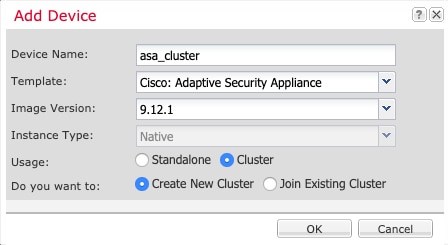
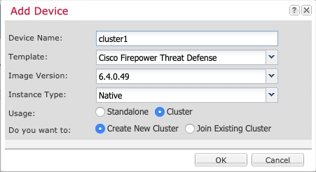
Standalone and Clustered Logical Devices

You can add the following logical device types:

  • Standalone—A standalone logical device operates as a standalone unit or as a unit in a High Availability pair.

  • Cluster—A clustered logical device lets you group multiple units together, providing all the convenience of a single device (management, integration into a network) while achieving the increased throughput and redundancy of multiple devices. Multiple module devices, like the Firepower 9300, support intra-chassis clustering. For the Firepower 9300, all three modules must participate in the cluster.

Requirements and Prerequisites for Logical Devices

See the following sections for requirements and prerequisites.

Requirements and Prerequisites for Hardware and Software Combinations

The Firepower 4100/9300 supports multiple models, security modules, application types, and high availability and scalability features. See the following requirements for allowed combinations.

Firepower 9300 Requirements

The Firepower 9300 includes 3 security module slots and multiple types of security modules. See the following requirements:

  • Security Module Types—

  • Clustering—All security modules in the cluster, whether it is intra-chassis or inter-chassis, must be the same type. You can have different quantities of installed security modules in each chassis, although all modules present in the chassis must belong to the cluster including any empty slots. For example, you can install 2 SM-36s in chassis 1, and 3 SM-36s in chassis 2.

  • High Availability—High Availability is only supported between same-type modules on the Firepower 9300.

  • ASA and FTD application types—

  • ASA or FTD versions—You can run different versions of an application instance type on separate modules. For example, you can install FTD 6.3 on module 1, FTD 6.4 on module 2, and FTD 6.5 on module 3.

Firepower 4100 Requirements

The Firepower 4100 comes in multiple models. See the following requirements:

  • Clustering—All chassis in the cluster must be the same model.

  • High Availability—High Availability is only supported between same-type models.

  • ASA and FTD application types—The Firepower 4100 can only run a single application type.

Requirements and Prerequisites for Clustering

Cluster Model Support

  • ASA on the Firepower 9300—Maximum 16 modules. For example, you can use 1 module in 16 chassis, or 2 modules in 8 chassis, or any combination that provides a maximum of 16 modules. Note that all modules in a chassis must belong to the cluster. Supported for intra-chassis, inter-chassis, and inter-site clustering.

  • ASA on the Firepower 4100 series—Maximum 16 chassis. Supported for inter-chassis and inter-site clustering.

  • FTD on the Firepower 9300—Maximum 6 modules. For example, you can use 2 modules in 3 chassis, or 3 modules in 2 chassis, or any combination that provides a maximum of 6 modules. Note that all modules in a chassis must belong to the cluster. Supported for intra-chassis and inter-chassis clustering.

  • FTD on the Firepower 4100 series—Maximum 6 chassis. Supported for inter-chassis clustering.

  • Radware DefensePro—Supported for intra-chassis clustering with the ASA.

  • Radware DefensePro—Supported for intra-chassis clustering with the FTD.

Clustering Hardware and Software Requirements

All chassis in a cluster:

  • For the Firepower 4100 series: All chassis must be the same model. For the Firepower 9300: All security modules must be the same type. For example, if you use clustering, all modules in the Firepower 9300 must be SM-40s. You can have different quantities of installed security modules in each chassis, although all modules present in the chassis must belong to the cluster including any empty slots.

  • Must run the identical FXOS software except at the time of an image upgrade.

  • Must include the same interface configuration for interfaces you assign to the cluster, such as the same Management interface, EtherChannels, active interfaces, speed and duplex, and so on. You can use different network module types on the chassis as long as the capacity matches for the same interface IDs and interfaces can successfully bundle in the same spanned EtherChannel. Note that all data interfaces must be EtherChannels in inter-chassis clustering. If you change the interfaces in FXOS after you enable clustering (by adding or removing interface modules, or configuring EtherChannels, for example), then perform the same changes on each chassis, starting with the data units, and ending with the control unit.

  • Must use the same NTP server. For Firepower Threat Defense, the Firepower Management Center must also use the same NTP server. Do not set the time manually.

  • ASA: Each FXOS chassis must be registered with the License Authority or satellite server. There is no extra cost for data units. For permanent license reservation, you must purchase separate licenses for each chassis. For Firepower Threat Defense, all licensing is handled by the Firepower Management Center.

Switch Requirements for Inter-Chassis Clustering

  • Be sure to complete the switch configuration and successfully connect all the EtherChannels from the chassis to the switch(es) before you configure clustering on the Firepower 4100/9300 chassis.

  • For supported switch characteristics, see Cisco FXOS Compatibility.

Sizing the Data Center Interconnect for Inter-Site Clustering

You should reserve bandwidth on the data center interconnect (DCI) for cluster control link traffic equivalent to the following calculation:

If the number of members differs at each site, use the larger number for your calculation. The minimum bandwidth for the DCI should not be less than the size of the cluster control link for one member.

For example:

  • For 4 members at 2 sites:

    • 4 cluster members total

    • 2 members at each site

    • 5 Gbps cluster control link per member

    Reserved DCI bandwidth = 5 Gbps (2/2 x 5 Gbps).

  • For 6 members at 3 sites, the size increases:

    • 6 cluster members total

    • 3 members at site 1, 2 members at site 2, and 1 member at site 3

    • 10 Gbps cluster control link per member

    Reserved DCI bandwidth = 15 Gbps (3/2 x 10 Gbps).

  • For 2 members at 2 sites:

    • 2 cluster members total

    • 1 member at each site

    • 10 Gbps cluster control link per member

    Reserved DCI bandwidth = 10 Gbps (1/2 x 10 Gbps = 5 Gbps; but the minimum bandwidth should not be less than the size of the cluster control link (10 Gbps)).

Requirements and Prerequisites for High Availability

  • The two units in a High Availability Failover configuration must:

    • Be on a separate chassis; intra-chassis High Availability for the Firepower 9300 is not supported.

    • Be the same model.

    • Have the same interfaces assigned to the High Availability logical devices.

    • Have the same number and types of interfaces. All interfaces must be preconfigured in FXOS identically before you enable High Availability.

  • For High Availability system requirements, see.

Guidelines and Limitations for Logical Devices

See the following sections for guidelines and limitations.

General Guidelines and Limitations

Firewall Mode

You can set the firewall mode to routed or transparent in the bootstrap configuration for the FTD.

High Availability

  • Configure high availability within the application configuration.

  • You can use any data interfaces as the failover and state links.

Context Mode

  • Multiple context mode is only supported on the ASA.

Clustering Guidelines and Limitations

Switches for Inter-Chassis Clustering

  • For the ASR 9006, if you want to set a non-default MTU, set the ASR interface MTU to be 14 bytes higher than the cluster device MTU. Otherwise, OSPF adjacency peering attempts may fail unless the mtu-ignore option is used. Note that the cluster device MTU should match the ASR IPv4 MTU.

  • On the switch(es) for the cluster control link interfaces, you can optionally enable Spanning Tree PortFast on the switch ports connected to the cluster unit to speed up the join process for new units.

  • On the switch, we recommend that you use one of the following EtherChannel load-balancing algorithms: source-dest-ip or source-dest-ip-port (see the Cisco Nexus OS and Cisco IOS port-channel load-balance command). Do not use a vlan keyword in the load-balance algorithm because it can cause unevenly distributed traffic to the devices in a cluster.

  • If you change the load-balancing algorithm of the EtherChannel on the switch, the EtherChannel interface on the switch temporarily stops forwarding traffic, and the Spanning Tree Protocol restarts. There will be a delay before traffic starts flowing again.

  • Some switches do not support dynamic port priority with LACP (active and standby links). You can disable dynamic port priority to provide better compatibility with Spanned EtherChannels.

  • Switches on the cluster control link path should not verify the L4 checksum. Redirected traffic over the cluster control link does not have a correct L4 checksum. Switches that verify the L4 checksum could cause traffic to be dropped.

  • Port-channel bundling downtime should not exceed the configured keepalive interval.

  • On Supervisor 2T EtherChannels, the default hash distribution algorithm is adaptive. To avoid asymmetric traffic in a VSS design, change the hash algorithm on the port-channel connected to the cluster device to fixed:

    router(config)# port-channel id hash-distribution fixed

    Do not change the algorithm globally; you may want to take advantage of the adaptive algorithm for the VSS peer link.

  • Firepower 4100/9300 clusters support LACP graceful convergence. So you can leave LACP graceful convergence enabled on connected Cisco Nexus switches.

  • When you see slow bundling of a Spanned EtherChannel on the switch, you can enable LACP rate fast for an individual interface on the switch. FXOS EtherChannels have the LACP rate set to fast by default. Note that some switches, such as the Nexus series, do not support LACP rate fast when performing in-service software upgrades (ISSUs), so we do not recommend using ISSUs with clustering.

EtherChannels for Inter-Chassis Clustering

    • In Catalyst 3750-X Cisco IOS software versions earlier than 15.1(1)S2, the cluster unit did not support connecting an EtherChannel to a switch stack. With default switch settings, if the cluster unit EtherChannel is connected cross stack, and if the control unit switch is powered down, then the EtherChannel connected to the remaining switch will not come up. To improve compatibility, set the stack-mac persistent timer command to a large enough value to account for reload time; for example, 8 minutes or 0 for indefinite. Or, you can upgrade to more a more stable switch software version, such as 15.1(1)S2.

    • Spanned vs. Device-Local EtherChannel Configuration—Be sure to configure the switch appropriately for Spanned EtherChannels vs. Device-local EtherChannels.

      • Spanned EtherChannels—For cluster unit Spanned EtherChannels, which span across all members of the cluster, the interfaces are combined into a single EtherChannel on the switch. Make sure each interface is in the same channel group on the switch.

      • Device-local EtherChannels—For cluster unit Device-local EtherChannels including any EtherChannels configured for the cluster control link, be sure to configure discrete EtherChannels on the switch; do not combine multiple cluster unit EtherChannels into one EtherChannel on the switch.

    Inter-Site Clustering

    See the following guidelines for inter-site clustering:

    • The cluster control link latency must be less than 20 ms round-trip time (RTT).

    • The cluster control link must be reliable, with no out-of-order or dropped packets; for example, you should use a dedicated link.

    • Do not configure connection rebalancing; you do not want connections rebalanced to cluster members at a different site.

    • The cluster implementation does not differentiate between members at multiple sites for incoming connections; therefore, connection roles for a given connection may span across sites. This is expected behavior. However, if you enable director localization, the local director role is always chosen from the same site as the connection owner (according to site ID). Also, the local director chooses a new owner at the same site if the original owner fails (Note: if the traffic is asymmetric across sites, and there is continuous traffic from the remote site after the original owner fails, then a unit from the remote site might become the new owner if it receives a data packet within the re-hosting window.).

    • For director localization, the following traffic types do not support localization: NAT or PAT traffic; SCTP-inspected traffic; Fragmentation owner query.

    • For transparent mode, if the cluster is placed between a pair of inside and outside routers (AKA North-South insertion), you must ensure that both inside routers share a MAC address, and also that both outside routers share a MAC address. When a cluster member at site 1 forwards a connection to a member at site 2, the destination MAC address is preserved. The packet will only reach the router at site 2 if the MAC address is the same as the router at site 1.

    • For transparent mode, if the cluster is placed between data networks and the gateway router at each site for firewalling between internal networks (AKA East-West insertion), then each gateway router should use a First Hop Redundancy Protocol (FHRP) such as HSRP to provide identical virtual IP and MAC address destinations at each site. The data VLANs are extended across the sites using Overlay Transport Virtualization (OTV), or something similar. You need to create filters to prevent traffic that is destined to the local gateway router from being sent over the DCI to the other site. If the gateway router becomes unreachable at one site, you need to remove any filters so traffic can successfully reach the other site’s gateway.

    • For routed mode using Spanned EtherChannel, configure site-specific MAC addresses. Extend the data VLANs across the sites using OTV, or something similar. You need to create filters to prevent traffic that is destined to the global MAC address from being sent over the DCI to the other site. If the cluster becomes unreachable at one site, you need to remove any filters so traffic can successfully reach the other site’s cluster units. Dynamic routing is not supported when an inter-site cluster acts as the first hop router for an extended segment.

    Additional Guidelines

    • When adding a unit to an existing cluster, or when reloading a unit, there will be a temporary, limited packet/connection drop; this is expected behavior. In some cases, the dropped packets can hang connections; for example, dropping a FIN/ACK packet for an FTP connection will make the FTP client hang. In this case, you need to reestablish the FTP connection.

    • If you use a Windows 2003 server connected to a Spanned EtherChannel interface, when the syslog server port is down, and the server does not throttle ICMP error messages, then large numbers of ICMP messages are sent back to the cluster. These messages can result in some units of the cluster experiencing high CPU, which can affect performance. We recommend that you throttle ICMP error messages.

    • We recommend connecting EtherChannels to a VSS or vPC for redundancy.

    • Within a chassis, you cannot cluster some security modules and run other security modules in standalone mode; you must include all security modules in the cluster.

    Defaults

    • The cluster health check feature is enabled by default with the holdtime of 3 seconds. Interface health monitoring is enabled on all interfaces by default.

    • The cluster auto-rejoin feature for a failed cluster control link is set to unlimited attempts every 5 minutes.

    • The cluster auto-rejoin feature for a failed data interface is set to 3 attempts every 5 minutes, with the increasing interval set to 2.

    • Connection replication delay of 5 seconds is enabled by default for HTTP traffic.

    Add a Standalone Logical Device

    Standalone logical devices can be used alone or as high availability units. For more information about high availability usage, see Add a High Availability Pair.

    Add a Standalone ASA

    Standalone logical devices work either alone or in a High Availability pair. On the Firepower 9300 with multiple security modules, you can deploy either a cluster or standalone devices. The cluster must use all modules, so you cannot mix and match a 2-module cluster plus a single standalone device, for example.

    You can deploy a routed firewall mode ASA from the Firepower 4100/9300 chassis.

    For multiple context mode, you must first deploy the logical device, and then enable multiple context mode in the ASA application.

    Before you begin

    • Download the application image you want to use for the logical device from Cisco.com, and then upload that image to the Firepower 4100/9300 chassis.


      Note

      For the Firepower 9300, you must install the same application instance type (ASA or FTD) on all modules in the chassis; different types are not supported at this time. Note that modules can run different versions of an application instance type.


    • Configure a management interface to use with the logical device. The management interface is required. Note that this management interface is not the same as the chassis management port that is used only for chassis management (and that appears at the top of the Interfaces tab as MGMT).

    • Gather the following information:

      • Interface IDs for this device

      • Management interface IP address and network mask

      • Gateway IP address

    Procedure


    Step 1

    Choose Logical Devices.

    Step 2

    Click , and set the following parameters:

    1. Provide a Device Name.

      This name is used by the chassis supervisor to configure management settings and to assign interfaces; it is not the device name used in the application configuration.

    2. For the Template, choose Cisco: Adaptive Security Appliance.

    3. Choose the Image Version.

    4. For the Usage, click the Standalone radio button.

    5. Click OK.

      You see the Provisioning - device name window.

    Step 3

    Expand the Data Ports area, and click each port that you want to assign to the device.

    You can only assign data interfaces that you previously enabled on the Interfaces page. You will later enable and configure these interfaces on the ASA, including setting the IP addresses.

    Step 4

    Click the device icon in the center of the screen.

    A dialog box appears where you can configure initial bootstrap settings. These settings are meant for initial deployment only, or for disaster recovery. For normal operation, you can later change most values in the application CLI configuration.

    Step 5

    On the General Information page, complete the following:

    1. (For the Firepower 9300) Under Security Module Selection click the security module that you want to use for this logical device.

    2. Choose the Management Interface.

      This interface is used to manage the logical device. This interface is separate from the chassis management port.

    3. Choose the management interface Address Type: IPv4 only, IPv6 only, or IPv4 and IPv6.

    4. Configure the Management IP address.

      Set a unique IP address for this interface.

    5. Enter a Network Mask or Prefix Length.

    6. Enter a Network Gateway address.

    Step 6

    Click the Settings tab.

    Step 7

    Enter and confirm a Password for the admin user.

    The pre-configured ASA admin user/password is useful for password recovery; if you have FXOS access, you can reset the admin user password if you forget it.

    Step 8

    Click OK to close the configuration dialog box.

    Step 9

    Click Save.

    The chassis deploys the logical device by downloading the specified software version and pushing the bootstrap configuration and management interface settings to the application instance. Check the Logical Devices page for the status of the new logical device. When the logical device shows its Status as online, you can start configuring the security policy in the application.

    Step 10

    See the ASA configuration guide to start configuring your security policy.


    Add a Standalone Firepower Threat Defense

    Standalone logical devices work either alone or in a High Availability pair. On the Firepower 9300 with multiple security modules, you can deploy either a cluster or standalone devices. The cluster must use all modules, so you cannot mix and match a 2-module cluster plus a single standalone device, for example.

    Before you begin

    • Download the application image you want to use for the logical device from Cisco.com, and then upload that image to the Firepower 4100/9300 chassis.


      Note

      For the Firepower 9300, you must install the same application instance type (ASA or FTD) on all modules in the chassis; different types are not supported at this time. Note that modules can run different versions of an application instance type.


    • Configure a management interface to use with the logical device. The management interface is required. Note that this management interface is not the same as the chassis management port that is used only for chassis management (and that appears at the top of the Interfaces tab as MGMT).

    • You must also configure at least one Data type interface. Optionally, you can also create a firepower-eventing interface to carry all event traffic (such as web events). See Interface Types for more information.

    • Gather the following information:

      • Interface IDs for this device

      • Management interface IP address and network mask

      • Gateway IP address

      • FMC IP address and/or NAT ID of your choosing

      • DNS server IP address

      • FTD hostname and domain name

    Procedure


    Step 1

    Choose Logical Devices.

    Step 2

    Click , and set the following parameters:

    1. Provide a Device Name.

      This name is used by the chassis supervisor to configure management settings and to assign interfaces; it is not the device name used in the application configuration.

    2. For the Template, choose Cisco Firepower Threat Defense.

    3. Choose the Image Version.

    4. For the Usage, click the Standalone radio button.

    5. Click OK.

      You see the Provisioning - device name window.

    Step 3

    Expand the Data Ports area, and click each interface that you want to assign to the device.

    You can only assign data interfaces that you previously enabled on the Interfaces page. You will later enable and configure these interfaces in FMC, including setting the IP addresses.

    Hardware Bypass-capable ports are shown with the following icon: . For certain interface modules, you can enable the Hardware Bypass feature for Inline Set interfaces only (see the FMC configuration guide). Hardware Bypass ensures that traffic continues to flow between an inline interface pair during a power outage. This feature can be used to maintain network connectivity in the case of software or hardware failures. If you do not assign both interfaces in a Hardware Bypass pair, you see a warning message to make sure your assignment is intentional. You do not need to use the Hardware Bypass feature, so you can assign single interfaces if you prefer.

    Step 4

    Click the device icon in the center of the screen.

    A dialog box appears where you can configure initial bootstrap settings. These settings are meant for initial deployment only, or for disaster recovery. For normal operation, you can later change most values in the application CLI configuration.

    Step 5

    On the General Information page, complete the following:

    1. (For the Firepower 9300) Under Security Module Selection click the security module that you want to use for this logical device.

    2. Choose the Management Interface.

      This interface is used to manage the logical device. This interface is separate from the chassis management port.

    3. Choose the management interface Address Type: IPv4 only, IPv6 only, or IPv4 and IPv6.

    4. Configure the Management IP address.

      Set a unique IP address for this interface.

    5. Enter a Network Mask or Prefix Length.

    6. Enter a Network Gateway address.

    Step 6

    On the Settings tab, complete the following:

    1. Enter the Firepower Management Center IP of the managing FMC.

    2. Enter the Search Domains as a comma-separated list.

    3. Choose the Firewall Mode: Transparent or Routed.

      In routed mode, the FTD is considered to be a router hop in the network. Each interface that you want to route between is on a different subnet. A transparent firewall, on the other hand, is a Layer 2 firewall that acts like a “bump in the wire,” or a “stealth firewall,” and is not seen as a router hop to connected devices.

      The firewall mode is only set at initial deployment. If you re-apply the bootstrap settings, this setting is not used.

    4. Enter the DNS Servers as a comma-separated list.

      The FTD uses DNS if you specify a hostname for the FMC, for example.

    5. Enter the Fully Qualified Hostname for the FTD.

    6. Enter a Registration Key to be shared between the FMC and the device during registration.

      You can choose any text string for this key between 1 and 37 characters; you will enter the same key on the FMC when you add the FTD.

    7. Enter a Password for the FTD admin user for CLI access.

    8. Choose the Eventing Interface on which Firepower events should be sent. If not specified, the management interface will be used.

      This interface must be defined as a Firepower-eventing interface.

    Step 7

    On the Agreement tab, read and accept the end user license agreement (EULA).

    Step 8

    Click OK to close the configuration dialog box.

    Step 9

    Click Save.

    The chassis deploys the logical device by downloading the specified software version and pushing the bootstrap configuration and management interface settings to the application instance. Check the Logical Devices page for the status of the new logical device. When the logical device shows its Status as online, you can start configuring the security policy in the application.

    Step 10

    See the FMC configuration guide to add the FTD as a managed device and start configuring your security policy.


    Add a High Availability Pair

    or High Availability (also known as failover) is configured within the application, not in FXOS. However, to prepare your chassis for high availability, see the following steps.

    Before you begin

    See .

    Procedure


    Step 1

    Allocate the same interfaces to each logical device.

    Step 2

    Allocate 1 or 2 data interfaces for the failover and state link(s).

    These interfaces exchange high availability traffic between the 2 chassis. We recommend that you use a 10 GB data interface for a combined failover and state link. If you have available interfaces, you can use separate failover and state links; the state link requires the most bandwidth. You cannot use the management-type interface for the failover or state link. We recommend that you use a switch between the chassis, with no other device on the same network segment as the failover interfaces.

    Step 3

    Enable High Availability on the logical devices.

    Step 4

    If you need to make interface changes after you enable High Availability, perform the changes on the standby unit first, and then perform the changes on the active unit.


    Add a Cluster

    Clustering lets you group multiple devices together as a single logical device. A cluster provides all the convenience of a single device (management, integration into a network) while achieving the increased throughput and redundancy of multiple devices. The Firepower 9300, which includes multiple modules, supports intra-chassis clustering where you group all modules within a single chassis into a cluster. You can also use inter-chassis clustering, where multiple chassis are grouped together; inter-chasis clustering is the only option for single module devices like the Firepower 4100 series.

    About Clustering on the Firepower 4100/9300 Chassis

    The cluster consists of multiple devices acting as a single logical unit. When you deploy a cluster on the Firepower 4100/9300 chassis, it does the following:

    • Creates a cluster-control link (by default, port-channel 48) for unit-to-unit communication.

      For intra-chassis clustering (Firepower 9300 only), this link utilizes the Firepower 9300 backplane for cluster communications.

      For inter-chassis clustering, you need to manually assign physical interface(s) to this EtherChannel for communications between chassis.

    • Creates the cluster bootstrap configuration within the application.

      When you deploy the cluster, the chassis supervisor pushes a minimal bootstrap configuration to each unit that includes the cluster name, cluster control link interface, and other cluster settings. Some parts of the bootstrap configuration may be user-configurable within the application if you want to customize your clustering environment.

    • Assigns data interfaces to the cluster as Spanned interfaces.

      For intra-chassis clustering, spanned interfaces are not limited to EtherChannels, like it is for inter-chassis clustering.The Firepower 9300 supervisor uses EtherChannel technology internally to load-balance traffic to multiple modules on a shared interface, so any data interface type works for Spanned mode. For inter-chassis clustering, you must use Spanned EtherChannels for all data interfaces.


      Note

      Individual interfaces are not supported, with the exception of a management interface.


    • Assigns a management interface to all units in the cluster.

    The following sections provide more detail about clustering concepts and implementation.

    Primary and Secondary Unit Roles

    One member of the cluster is the primary unit. The primary unit is determined automatically. All other members are secondary units.

    You must perform all configuration on the primary unit only; the configuration is then replicated to the secondary units.

    Cluster Control Link

    The cluster control link is automatically created using the Port-channel 48 interface.

    For intra-chassis clustering, this interface has no member interfaces. This Cluster type EtherChannel utilizes the Firepower 9300 backplane for cluster communications for intra-chassis clustering. For inter-chassis clustering, you must add one or more interfaces to the EtherChannel.

    For a 2-member inter-chassis cluster, do not directly connect the cluster control link from one chassis to the other chassis. If you directly connect the interfaces, then when one unit fails, the cluster control link fails, and thus the remaining healthy unit fails. If you connect the cluster control link through a switch, then the cluster control link remains up for the healthy unit.

    Cluster control link traffic includes both control and data traffic.

    Size the Cluster Control Link for Inter-Chassis Clustering

    If possible, you should size the cluster control link to match the expected throughput of each chassis so the cluster-control link can handle the worst-case scenarios.

    Cluster control link traffic is comprised mainly of state update and forwarded packets. The amount of traffic at any given time on the cluster control link varies. The amount of forwarded traffic depends on the load-balancing efficacy or whether there is a lot of traffic for centralized features. For example:

    • NAT results in poor load balancing of connections, and the need to rebalance all returning traffic to the correct units.

    • When membership changes, the cluster needs to rebalance a large number of connections, thus temporarily using a large amount of cluster control link bandwidth.

    A higher-bandwidth cluster control link helps the cluster to converge faster when there are membership changes and prevents throughput bottlenecks.


    Note

    If your cluster has large amounts of asymmetric (rebalanced) traffic, then you should increase the cluster control link size.


    Cluster Control Link Redundancy for Inter-Chassis Clustering

    The following diagram shows how to use an EtherChannel as a cluster control link in a Virtual Switching System (VSS) or Virtual Port Channel (vPC) environment. All links in the EtherChannel are active. When the switch is part of a VSS or vPC, then you can connect Firepower 4100/9300 chassis interfaces within the same EtherChannel to separate switches in the VSS or vPC. The switch interfaces are members of the same EtherChannel port-channel interface, because the separate switches act like a single switch. Note that this EtherChannel is device-local, not a Spanned EtherChannel.

    Cluster Control Link Reliability for Inter-Chassis Clustering

    To ensure cluster control link functionality, be sure the round-trip time (RTT) between units is less than 20 ms. This maximum latency enhances compatibility with cluster members installed at different geographical sites. To check your latency, perform a ping on the cluster control link between units.

    The cluster control link must be reliable, with no out-of-order or dropped packets; for example, for inter-site deployment, you should use a dedicated link.

    Cluster Control Link Network

    The Firepower 4100/9300 chassis auto-generates the cluster control link interface IP address for each unit based on the chassis ID and slot ID: 127.2.chassis_id.slot_id. The cluster control link network cannot include any routers between units; only Layer 2 switching is allowed. For inter-site traffic, Cisco recommends using Overlay Transport Virtualization (OTV).

    Management Network

    We recommend connecting all units to a single management network. This network is separate from the cluster control link.

    Management Interface

    You must assign a Management type interface to the cluster. This interface is a special individual interface as opposed to a Spanned interface. The management interface lets you connect directly to each unit.

    For the ASA, the Main cluster IP address is a fixed address for the cluster that always belongs to the current primary unit. You must configure a range of addresses so that each unit, including the current primary unit, can use a Local address from the range. The Main cluster IP address provides consistent management access to an address; when a primary unit changes, the Main cluster IP address moves to the new primary unit, so management of the cluster continues seamlessly. The Local IP address is used for routing, and is also useful for troubleshooting. For example, you can manage the cluster by connecting to the Main cluster IP address, which is always attached to the current primary unit. To manage an individual member, you can connect to the Local IP address. For outbound management traffic such as TFTP or syslog, each unit, including the primary unit, uses the Local IP address to connect to the server.

    For the Firepower Threat Defense, assign a management IP address to each unit on the same network. Use these IP addresses when you add each unit to the FMC.

    Spanned EtherChannels

    You can group one or more interfaces per chassis into an EtherChannel that spans all chassis in the cluster. The EtherChannel aggregates the traffic across all the available active interfaces in the channel. A Spanned EtherChannel can be configured in both routed and transparent firewall modes. In routed mode, the EtherChannel is configured as a routed interface with a single IP address. In transparent mode, the IP address is assigned to the BVI, not to the bridge group member interface. The EtherChannel inherently provides load balancing as part of basic operation.

    Inter-Site Clustering

    For inter-site installations, you can take advantage of clustering as long as you follow the recommended guidelines.

    You can configure each cluster chassis to belong to a separate site ID.

    Site IDs work with site-specific MAC addresses and IP addresses. Packets sourced from the cluster use a site-specific MAC address and IP address, while packets received by the cluster use a global MAC address and IP address. This feature prevents the switches from learning the same global MAC address from both sites on two different ports, which causes MAC flapping; instead, they only learn the site MAC address. Site-specific MAC addresses and IP address are supported for routed mode using Spanned EtherChannels only.

    Site IDs are also used to enable flow mobility using LISP inspection, director localization to improve performance and reduce round-trip time latency for inter-site clustering for data centers.

    See the following sections for more information about inter-site clustering:

    Add an ASA Cluster

    You can add a single Firepower 9300 chassis as an intra-chassis cluster, or add multiple chassis for inter-chassis clustering. For inter-chassis clustering, you must configure each chassis separately. Add the cluster on one chassis; you can then copy the bootstrap configuration from the first chassis to the next chassis for ease of deployment

    Create an ASA Cluster

    Set the scope to the image version.

    You can easily deploy the cluster from the Firepower 4100/9300 chassis supervisor. All initial configuration is automatically generated for each unit.

    For inter-chassis clustering, you must configure each chassis separately. Deploy the cluster on one chassis; you can then copy the bootstrap configuration from the first chassis to the next chassis for ease of deployment.

    In a Firepower 9300 chassis, you must enable clustering for all 3 module slots, even if you do not have a module installed. If you do not configure all 3 modules, the cluster will not come up.

    For multiple context mode, you must first deploy the logical device, and then enable multiple context mode in the ASA application.

    Before you begin
    • Download the application image you want to use for the logical device from Cisco.com, and then upload that image to the Firepower 4100/9300 chassis.

    • Gather the following information:

      • Management interface ID, IP address, and network mask

      • Gateway IP address

    Procedure

    Step 1

    Configure interfaces.

    1. Add at least one Data type interface or EtherChannel (also known as a port-channel) before you deploy the cluster. See Add an EtherChannel (Port Channel) or Configure a Physical Interface.

      For inter-chassis clustering, all data interfaces must be Spanned EtherChannels with at least one member interface. Add the same EtherChannels on each chassis. Combine the member interfaces from all cluster units into a single EtherChannel on the switch. See Clustering Guidelines and Limitations for more information about EtherChannels for inter-chassis clustering.

    2. Add a Management type interface or EtherChannel. See Add an EtherChannel (Port Channel) or Configure a Physical Interface.

      The management interface is required. Note that this management interface is not the same as the chassis management interface that is used only for chassis management (in FXOS, you might see the chassis management interface displayed as MGMT, management0, or other similar names).

      For inter-chassis clustering, add the same Management interface on each chassis.

    3. For inter-chassis clustering, add a member interface to the cluster control link EtherChannel (by default, port-channel 48). See Add an EtherChannel (Port Channel).

      Do not add a member interface for intra-chassis clustering. If you add a member, the chassis assumes this cluster will be inter-chassis, and will only allow you to use Spanned EtherChannels, for example.

      On the Interfaces tab, the port-channel 48 cluster type interface shows the Operation State as failed if it does not include any member interfaces. For intra-chassis clustering, this EtherChannel does not require any member interfaces, and you can ignore this Operational State.

      Add the same member interfaces on each chassis. The cluster control link is a device-local EtherChannel on each chassis. Use separate EtherChannels on the switch per device. See Clustering Guidelines and Limitations for more information about EtherChannels for inter-chassis clustering.

    Step 2

    Choose Logical Devices.

    Step 3

    Click , and set the following parameters:

    1. Provide a Device Name.

      This name is used internally by the chassis supervisor to configure management settings and to assign interfaces; it is not the device name used in the application configuration.

    2. For the Template, choose Cisco Adaptive Security Appliance.

    3. Choose the Image Version.

    4. For the Instance Type, only the Native type is supported.

    5. Click the Create New Cluster radio button.

    6. Click OK.

      You see the Provisioning - device name window.

    Step 4

    Choose the interfaces you want to assign to this cluster.

    All valid interfaces are assigned by default.

    Step 5

    Click the device icon in the center of the screen.

    A dialog box appears where you can configure initial bootstrap settings. These settings are meant for initial deployment only, or for disaster recovery. For normal operation, you can later change most values in the application CLI configuration.

    Step 6

    On the Cluster Information page, complete the following.

    1. For inter-chassis clustering, in the Chassis ID field, enter a chassis ID. Each chassis in the cluster must use a unique ID.

      This field only appears if you added a member interface to cluster control link Port-Channel 48.

    2. For inter-site clustering, in the Site ID field, enter the site ID for this chassis between 1 and 8.

    3. In the Cluster Key field, configure an authentication key for control traffic on the cluster control link.

      The shared secret is an ASCII string from 1 to 63 characters. The shared secret is used to generate the key. This option does not affect datapath traffic, including connection state update and forwarded packets, which are always sent in the clear.

    4. Set the Cluster Group Name, which is the cluster group name in the logical device configuration.

      The name must be an ASCII string from 1 to 38 characters.

    5. Choose the Management Interface.

      This interface is used to manage the logical device. This interface is separate from the chassis management port.

    6. Choose the Address Type for the management interface.

      This information is used to configure a management interface in the ASA configuration. Set the following information:

      • Management IP Pool—Configure a pool of Local IP addresses, one of which will be assigned to each cluster unit for the interface, by entering the starting and ending addresses separated by a hyphen.

        Include at least as many addresses as there are units in the cluster. Note that for the Firepower 9300, you must include 3 addresses per chassis, even if you do not have all module slots filled. If you plan to expand the cluster, include additional addresses. The Virtual IP address (known as the Main cluster IP address) that belongs to the current control unit is not a part of this pool; be sure to reserve an IP address on the same network for the Main cluster IP address. You can use IPv4 and/or IPv6 addresses.

      • Network Mask or Prefix Length

      • Network Gateway

      • Virtual IP address—Set the management IP address of the current control unit. This IP address must be on the same network as the cluster pool addresses, but not be part of the pool.

    Step 7

    On the Settings page, complte the following.

    1. Enter and confirm a Password for the admin user.

      The pre-configured ASA admin user is useful for password recovery; if you have FXOS access, you can reset the admin user password if you forget it.

    Step 8

    Click OK to close the configuration dialog box.

    Step 9

    Click Save.

    The chassis deploys the logical device by downloading the specified software version and pushing the bootstrap configuration and management interface settings to the application instance. Check the Logical Devices page for the status of the new logical device. When the logical device shows its Status as online, you can add the remaining cluster chassis, or for intra-chassis clusteringstart configuring the cluster in the application. You may see the "Security module not responding" status as part of the process; this status is normal and is temporary.

    Step 10

    For inter-chassis clustering, add the next chassis to the cluster:

    1. On the first chassis Firepower Chassis Manager, click the Show Configuration icon at the top right; copy the displayed cluster configuration.

    2. Connect to the Firepower Chassis Manager on the next chassis, and add a logical device according to this procedure.

    3. Choose Join an Existing Cluster.

    4. lick OK.

    5. In the Copy Cluster Details box, paste in the cluster configuration from the first chassis, and click OK.

    6. Click the device icon in the center of the screen. The cluster information is mostly pre-filled, but you must change the following settings:

      • Chassis ID—Enter a unique chassis ID.

      • Site ID—Enter the correct site ID.

      • Cluster Key—(Not prefilled) Enter the same cluster key.

      Click OK.

    7. Click Save.

      The chassis deploys the logical device by downloading the specified software version and pushing the bootstrap configuration and management interface settings to the application instance. Check the Logical Devices page for each cluster member for the status of the new logical device. When the logical device for each cluster member shows its Status as online, you can start configuring the cluster in the application. You may see the "Security module not responding" status as part of the process; this status is normal and is temporary.

    Step 11

    Connect to the control unit ASA to customize your clustering configuration.


    Add More Cluster Members

    Add or replace an ASA cluster member.


    Note

    This procedure only applies to adding or replacing a chassis; if you are adding or replacing a module to a Firepower 9300 where clustering is already enabled, the module will be added automatically.


    Before you begin
    • Make sure your existing cluster has enough IP addresses in the management IP address pool for this new member. If not, you need to edit the existing cluster bootstrap configuration on each chassis before you add this new member. This change causes a restart of the logical device.

    • The interface configuration must be the same on the new chassis. You can export and import FXOS chassis configuration to make this process easier.

    • For multiple context mode, enable multiple context mode in the ASA application on the first cluster member; additional cluster members will inherit the multiple context mode configuration automatically.

    Procedure

    Step 1

    On an existing cluster chassis Firepower Chassis Manager, choose Logical Devices to open the Logical Devices page.

    Step 2

    Click the Show Configuration icon (Show Configuration icon) at the top right; copy the displayed cluster configuration.

    Step 3

    Connect to the Firepower Chassis Manager on the new chassis, and click .

    Step 4

    For the Device Name, provide a name for the logical device.

    Step 5

    For the Template, choose Cisco Adaptive Security Appliance.

    Step 6

    For the Image Version, choose the ASA software version.

    Step 7

    For the Device Mode, click the Cluster radio button.

    Step 8

    Choose Join an Existing Cluster.

    Step 9

    lick OK.

    Step 10

    In the Copy Cluster Details box, paste in the cluster configuration from the first chassis, and click OK.

    Step 11

    Click the device icon in the center of the screen. The cluster information is mostly pre-filled, but you must change the following settings:

    • Chassis ID—Enter a unique chassis ID.

    • Site ID—Enter the correct site ID.

    • Cluster Key—(Not prefilled) Enter the same cluster key.

    Click OK.

    Step 12

    Click Save.

    The chassis deploys the logical device by downloading the specified software version and pushing the bootstrap configuration and management interface settings to the application instance. Check the Logical Devices page for each cluster member for the status of the new logical device. When the logical device for each cluster member shows its Status as online, you can start configuring the cluster in the application. You may see the "Security module not responding" status as part of the process; this status is normal and is temporary.


    Add a Firepower Threat Defense Cluster

    You can add a single Firepower 9300 chassis as an intra-chassis cluster, or add multiple chassis for inter-chassis clustering.

    For inter-chassis clustering, you must configure each chassis separately. Add the cluster on one chassis; you can then copy the bootstrap configuration from the first chassis to the next chassis for ease of deployment

    Create a Firepower Threat Defense Cluster

    You can easily deploy the cluster from the Firepower 4100/9300 chassis supervisor. All initial configuration is automatically generated for each unit.

    For inter-chassis clustering, you must configure each chassis separately. Deploy the cluster on one chassis; you can then copy the bootstrap configuration from the first chassis to the next chassis for ease of deployment.

    In a Firepower 9300 chassis, you must enable clustering for all 3 module slots, even if you do not have a module installed. If you do not configure all 3 modules, the cluster will not come up.

    Before you begin
    • Download the application image you want to use for the logical device from Cisco.com, and then upload that image to the Firepower 4100/9300 chassis.

    • Gather the following information:

      • Management interface ID, IP addresses, and network mask

      • Gateway IP address

      • FMC IP address and/or NAT ID of your choosing

      • DNS server IP address

      • FTD hostname and domain name

    Procedure

    Step 1

    Configure interfaces.

    1. Add at least one Data type interface or EtherChannel (also known as a port-channel) before you deploy the cluster. See Add an EtherChannel (Port Channel) or Configure a Physical Interface.

      For inter-chassis clustering, all data interfaces must be Spanned EtherChannels with at least one member interface. Add the same EtherChannels on each chassis. Combine the member interfaces from all cluster units into a single EtherChannel on the switch. See Clustering Guidelines and Limitations for more information about EtherChannels for inter-chassis clustering.

    2. Add a Management type interface or EtherChannel. See Add an EtherChannel (Port Channel) or Configure a Physical Interface.

      The management interface is required. Note that this management interface is not the same as the chassis management interface that is used only for chassis management (in FXOS, you might see the chassis management interface displayed as MGMT, management0, or other similar names).

      For inter-chassis clustering, add the same Management interface on each chassis.

    3. For inter-chassis clustering, add a member interface to the cluster control link EtherChannel (by default, port-channel 48). See Add an EtherChannel (Port Channel).

      Do not add a member interface for intra-chassis clustering. If you add a member, the chassis assumes this cluster will be inter-chassis, and will only allow you to use Spanned EtherChannels, for example.

      On the Interfaces tab, the port-channel 48 cluster type interface shows the Operation State as failed if it does not include any member interfaces. For intra-chassis clustering, this EtherChannel does not require any member interfaces, and you can ignore this Operational State.

      Add the same member interfaces on each chassis. The cluster control link is a device-local EtherChannel on each chassis. Use separate EtherChannels on the switch per device. See Clustering Guidelines and Limitations for more information about EtherChannels for inter-chassis clustering.

    4. (Optional) Add a Firepower-eventing interface. See Add an EtherChannel (Port Channel) or Configure a Physical Interface.

      This interface is a secondary management interface for FTD devices. To use this interface, you must configure its IP address and other parameters at the FTD CLI. For example, you can separate management traffic from events (such as web events). See the configure network commands in the Firepower Threat Defense command reference.

      For inter-chassis clustering, add the same eventing interface on each chassis.

    Step 2

    Choose Logical Devices.

    Step 3

    Click , and set the following parameters:

    1. Provide a Device Name.

      This name is used internally by the chassis supervisor to configure management settings and to assign interfaces; it is not the device name used in the application configuration.

    2. For the Template, choose Cisco Firepower Threat Defense.

    3. Choose the Image Version.

    4. For the Instance Type, only the Native type is supported.

    5. Click the Create New Cluster radio button.

    6. Click OK.

      You see the Provisioning - device name window.

    Step 4

    Choose the interfaces you want to assign to this cluster.

    All valid interfaces are assigned by default.

    Step 5

    Click the device icon in the center of the screen.

    A dialog box appears where you can configure initial bootstrap settings. These settings are meant for initial deployment only, or for disaster recovery. For normal operation, you can later change most values in the application CLI configuration.

    Step 6

    On the Cluster Information page, complete the following.

    Figure 1.
    1. For inter-chassis clustering, in the Chassis ID field, enter a chassis ID. Each chassis in the cluster must use a unique ID.

      This field only appears if you added a member interface to cluster control link Port-Channel 48.

    2. For inter-site clustering, in the Site ID field, enter the site ID for this chassis between 1 and 8. FlexConfig feature. Additional inter-site cluster customizations to enhance redundancy and stability, such as director localization, and cluster flow mobility, are only configurable using the Firepower Management Center FlexConfig feature.

    3. In the Cluster Key field, configure an authentication key for control traffic on the cluster control link.

      The shared secret is an ASCII string from 1 to 63 characters. The shared secret is used to generate the key. This option does not affect datapath traffic, including connection state update and forwarded packets, which are always sent in the clear.

    4. Set the Cluster Group Name, which is the cluster group name in the logical device configuration.

      The name must be an ASCII string from 1 to 38 characters.

    5. Choose the Management Interface.

      This interface is used to manage the logical device. This interface is separate from the chassis management port.

      If you assign a Hardware Bypass-capable interface as the Management interface, you see a warning message to make sure your assignment is intentional.

    Step 7

    On the Settings page, complete the following.

    1. In the Registration Key field, enter the key to be shared between the Firepower Management Center and the cluster members during registration.

      You can choose any text string for this key between 1 and 37 characters; you will enter the same key on the FMC when you add the FTD.

    2. Enter a Password for the FTD admin user for CLI access.

    3. In the Firepower Management Center IP field, enter the IP address of the managing Firepower Management Center.

    4. (Optional) In the Search Domains field, enter a comma-separated list of search domains for the management network.

    5. (Optional) From the Firewall Mode drop-down list, choose Transparent or Routed.

      In routed mode, the FTD is considered to be a router hop in the network. Each interface that you want to route between is on a different subnet. A transparent firewall, on the other hand, is a Layer 2 firewall that acts like a “bump in the wire,” or a “stealth firewall,” and is not seen as a router hop to connected devices.

      The firewall mode is only set at initial deployment. If you re-apply the bootstrap settings, this setting is not used.

    6. (Optional) In the DNS Servers field, enter a comma-separated list of DNS servers.

      The FTD uses DNS if you specify a hostname for the FMC, for example.

    7. (Optional) In the Fully Qualified Hostname field, enter a fully qualified name for the FTD device.

      Valid characters are the letters from a to z, the digits from 0 to 9, the dot (.), and the hyphen (-); maximum number of characters is 253.

    8. (Optional) From the Eventing Interface drop-down list, choose the interface on which Firepower events should be sent. If not specified, the management interface will be used.

      To specify a separate interface to use for Firepower events, you must configure an interface as a firepower-eventing interface. If you assign a Hardware Bypass-capable interface as the Eventing interface, you see a warning message to make sure your assignment is intentional.

    Step 8

    On the Interface Information page, configure a management IP address for each security module in the cluster. Select the type of address from the Address Type drop-down list and then complete the following for each security module.

    Note 

    You must set the IP address for all 3 module slots in a chassis, even if you do not have a module installed. If you do not configure all 3 modules, the cluster will not come up.

    1. In the Management IP field, configure an IP address.

      Specify a unique IP address on the same network for each module.

    2. Enter a Network Mask or Prefix Length.

    3. Enter a Network Gateway address.

    Step 9

    On the Agreement tab, read and accept the end user license agreement (EULA).

    Step 10

    Click OK to close the configuration dialog box.

    Step 11

    Click Save.

    The chassis deploys the logical device by downloading the specified software version and pushing the bootstrap configuration and management interface settings to the application instance. Check the Logical Devices page for the status of the new logical device. When the logical device shows its Status as online, you can add the remaining cluster chassis, or for intra-chassis clusteringstart configuring the cluster in the application. You may see the "Security module not responding" status as part of the process; this status is normal and is temporary.

    Step 12

    For inter-chassis clustering, add the next chassis to the cluster:

    1. On the first chassis Firepower Chassis Manager, click the Show Configuration icon at the top right; copy the displayed cluster configuration.

    2. Connect to the Firepower Chassis Manager on the next chassis, and add a logical device according to this procedure.

    3. Choose Join an Existing Cluster.

    4. lick OK.

    5. In the Copy Cluster Details box, paste in the cluster configuration from the first chassis, and click OK.

    6. Click the device icon in the center of the screen. The cluster information is mostly pre-filled, but you must change the following settings:

      • Chassis ID—Enter a unique chassis ID.

      • Site ID—For inter-site clustering, enter the site ID for this chassis between 1 and 8. Additional inter-site cluster customizations to enhance redundancy and stability, such as director localization, and cluster flow mobility, are only configurable using the Firepower Management Center FlexConfig feature.

      • Cluster Key—(Not prefilled) Enter the same cluster key.

      • Management IP—Change the management address for each module to be a unique IP address on the same network as the other cluster members.

      Click OK.

    7. Click Save.

      The chassis deploys the logical device by downloading the specified software version and pushing the bootstrap configuration and management interface settings to the application instance. Check the Logical Devices page for each cluster member for the status of the new logical device. When the logical device for each cluster member shows its Status as online, you can start configuring the cluster in the application. You may see the "Security module not responding" status as part of the process; this status is normal and is temporary.

    Step 13

    Add each unit separately to the Firepower Management Center using the management IP addresses, and then group them into a cluster at the web interface.

    All cluster units must be in a successfully-formed cluster on FXOS prior to adding them to Firepower Management Center.


    Add More Cluster Units

    Add or replace a FTD cluster unit in an existing cluster.


    Note

    The FXOS steps in this procedure only apply to adding a new chassis; if you are adding a new module to a Firepower 9300 where clustering is already enabled, the module will be added automatically. However, you must still add the new module to the Firepower Management Center; skip to the Firepower Management Center steps.


    Before you begin
    • In the case of a replacement, you must delete the old cluster unit from the Firepower Management Center. When you replace it with a new unit, it is considered to be a new device on the Firepower Management Center.

    • The interface configuration must be the same on the new chassis. You can export and import FXOS chassis configuration to make this process easier.

    Procedure

    Step 1

    On an existing cluster chassis Firepower Chassis Manager, choose Logical Devices to open the Logical Devices page.

    Step 2

    Click the Show Configuration icon at the top right; copy the displayed cluster configuration.

    Step 3

    Connect to the Firepower Chassis Manager on the new chassis, and click Add Device.

    Step 4

    For the Device Name, provide a name for the logical device.

    Step 5

    For the Template, choose Cisco Firepower Threat Defense.

    Step 6

    For the Image Version, choose the FTD software version.

    Step 7

    For the Device Mode, click the Cluster radio button.

    Step 8

    Choose Join an Existing Cluster.

    Step 9

    lick OK.

    Step 10

    In the Copy Cluster Details box, paste in the cluster configuration from the first chassis, and click OK.

    Step 11

    Click the device icon in the center of the screen. The cluster information is mostly pre-filled, but you must change the following settings:

    • Chassis ID—Enter a unique chassis ID.

    • Site ID—For inter-site clustering, enter the site ID for this chassis between 1 and 8. This feature is only configurable using the Firepower Management Center FlexConfig feature.

    • Cluster Key—(Not prefilled) Enter the same cluster key.

    • Management IP—Change the management address for each module to be a unique IP address on the same network as the other cluster members.

    Click OK.

    Step 12

    Click Save.

    The chassis deploys the logical device by downloading the specified software version and pushing the bootstrap configuration and management interface settings to the application instance. Check the Logical Devices page for each cluster member for the status of the new logical device. When the logical device for each cluster member shows its Status as online, you can start configuring the cluster in the application. You may see the "Security module not responding" status as part of the process; this status is normal and is temporary.


    Configure Radware DefensePro

    The Cisco Firepower 4100/9300 chassis can support multiple services (for example, a firewall and a third-party DDoS application) on a single blade. These applications and services can be linked together to form a Service Chain.

    About Radware DefensePro

    In the current supported Service Chaining configuration, the third-party Radware DefensePro virtual platform can be installed to run in front of the ASA firewall, or in front of Firepower Threat Defense. Radware DefensePro is a KVM-based virtual platform that provides distributed denial-of-service (DDoS) detection and mitigation capabilities on the Firepower 4100/9300 chassis. When Service Chaining is enabled on your Firepower 4100/9300 chassis, traffic from the network must first pass through the DefensePro virtual platform before reaching the main ASA or Firepower Threat Defense firewall.


    Note

    • The Radware DefensePro virtual platform may be referred to as Radware vDP (virtual DefensePro), or simply vDP.

    • The Radware DefensePro virtual platform may occasionally be referred to as a Link Decorator.


    Prerequisites for Radware DefensePro

    Prior to deploying Radware DefensePro on your Firepower 4100/9300 chassis, you must configure the Firepower 4100/9300 chassis to use an NTP Server with the etc/UTC Time Zone. For more information about setting the date and time in your Firepower 4100/9300 chassis, see Setting the Date and Time.

    Guidelines for Service Chaining

    Models

    • ASA—The Radware DefensePro (vDP) platform is supported with ASA on the following models:

      • Firepower 9300

      • Firepower 4110

      • Firepower 4120—You must use the CLI to deploy Radware DefensePro on this platform; the Firepower Chassis Manager does not yet support this functionality.

      • Firepower 4140—You must use the CLI to deploy Radware DefensePro on this platform; the Firepower Chassis Manager does not yet support this functionality.

      • Firepower 4150

    • Firepower Threat Defense—The Radware DefensePro platform is supported with Firepower Threat Defense on the following models:

      • Firepower 9300

      • Firepower 4110—Note you must deploy the decorator at the same time as the logical device. You cannot install the decorator after the logical device is already configured on the device.

      • Firepower 4120—Note you must deploy the decorator at the same time as the logical device. You cannot install the decorator after the logical device is already configured on the device.

      • Firepower 4140

      • Firepower 4150

    Additional Guidelines

    • Service Chaining is not supported in an inter-chassis cluster configuration. However, the Radware DefensePro (vDP) application can be deployed in a standalone configuration in an inter-chassis cluster scenario.

    Configure Radware DefensePro on a Standalone Logical Device

    The following procedure shows how to install Radware DefensePro in a single Service Chain in front of a standalone ASA or Firepower Threat Defense logical device.


    Note

    Once you set the vDP application and commit the change at the end of this procedure, the logical device (ASA or FTD) will reboot.

    If you are installing Radware vDP in front of ASA on a Firepower 4120 or 4140 security appliance, you must use the FXOS CLI to deploy the decorator. For full CLI instructions on how to install and configure Radware DefensePro in a service chain in front of ASA on Firepower 4100 devices, refer to the FXOS CLI configuration guide.


    Before you begin

    Procedure


    Step 1

    If you want to use a separate management interface for vDP, enable the interface and set it to be the mgmt type according to Configure a Physical Interface. Otherwise, you can share the application management interface.

    Step 2

    Choose Logical Devices to open the Logical Devices page.

    The Logical Devices page shows a list of configured logical devices on the chassis. If no logical devices have been configured, a message stating so is shown.

    Step 3

    Create a standalone ASA or Firepower Threat Defense Logical Device (see Add a Standalone ASA or Add a Standalone Firepower Threat Defense).

    Step 4

    In the Decorators area, select vDP. The Radware: Virtual DefensePro - Configuration window appears. Configure the following fields under the General Information tab.

    Step 5

    If you have more than one vDP version uploaded to the Firepower 4100/9300 chassis, select the version you want to use in the Version drop-down.

    Step 6

    Under the Management Interface drop-down, choose the management interface you created in step 1 of this procedure.

    Step 7

    Select the default Address Type, IPv4 only, IPv6 only, or IPv4 and IPv6.

    Step 8

    Configure the following fields, based on your Address Type selection from the previous step.

    1. In the Management IP field, configure a local IP address.

    2. IPv4 only: Enter a Network Mask.

      IPv6 only: Enter a Prefix Length.

    3. Enter a Network Gateway address.

    Step 9

    Click the checkbox next to each data port that you want to assign to the device.

    Step 10

    Click OK.

    Step 11

    Click Save.

    The Firepower eXtensible Operating System deploys the logical device by downloading the specified software version and pushing the bootstrap configuration and management interface settings to the specified security module.


    What to do next

    Set a password for the DefensePro application. Note that the application does not come online until you set a password. For more information, see the Radware DefensePro DDoS Mitigation User Guide on cisco.com.

    Configure Radware DefensePro on an Intra-Chassis Cluster

    The following procedure shows how to install the Radware DefensePro image, and configure it in a Service Chain in front of an ASA or Firepower Threat Defense intra-chassis cluster.


    Note

    Service Chaining is not supported in an inter-chassis cluster configuration. However, the Radware DefensePro application can be deployed in a standalone configuration in an inter-chassis cluster scenario.


    Before you begin

    Procedure


    Step 1

    If you want to use a separate management interface for vDP, enable the interface and set it to be the mgmt type according to Configure a Physical Interface. Otherwise, you can share the application management interface.

    Step 2

    Configure an ASA or Firepower Threat Defense intra-chassis cluster (see Create an ASA Cluster or Create a Firepower Threat Defense Cluster ).

    Note that before you click Save at the end of the procedure to configure the intra-chassis cluster, you must first follow the following steps to add a vDP decorator to the cluster.

    Step 3

    In the Decorators area, select vDP. The Radware: Virtual DefensePro - Configuration dialog box appears. Configure the following fields under the General Information tab.

    Step 4

    If you have more than one vDP version uploaded to the Firepower 4100/9300 chassis, select the vDP version you want to use in the Version drop-down.

    Step 5

    Under the Management Interface drop-down, choose a management interface.

    Step 6

    Click the checkbox next to each data port that you want to assign to the vDP decorator.

    Step 7

    Click the Interface Information tab.

    Step 8

    Select the Address Type to be used, IPv4 only, IPv6 only, or IPv4 and IPv6.

    Step 9

    Configure the following fields for each Security Module. Note that the fields that display depend on your Address Type selection from the previous step.

    1. In the Management IP field, configure a local IP address.

    2. IPv4 only: Enter a Network Mask.

      IPv6 only: Enter a Prefix Length.

    3. Enter a Network Gateway address.

    Step 10

    Click OK.

    Step 11

    Click Save.

    The Firepower eXtensible Operating System deploys the logical device by downloading the specified software version and pushing the bootstrap configuration and management interface settings to the specified security module.

    Step 12

    Choose Logical Devices to open the Logical Devices page.

    Step 13

    Scroll through the list of configured logical devices to the entries for vDP. Verify their Attributes listed in the Management IP column.

    • If the CLUSTER-ROLE element displays as unknown for the DefensePro instances, you must enter the DefensePro application and configure the Control unit IP address to complete the creation of the vDP cluster.
    • If the CLUSTER-ROLE element displays as primary or secondary for the DefensePro instances, the applications are online and formed in a cluster.

    What to do next

    Set a password for the DefensePro application. Note that the application does not come online until you set a password. For more information, see the Radware DefensePro DDoS Mitigation User Guide on cisco.com.

    Open UDP/TCP Ports and Enable vDP Web Services

    The Radware APSolute Vision Manager interfaces communicate with the Radware vDP appliation using various UDP/TCP ports. In orer for the vDP application to communicate with the APSolute Vision Manager, you must ensure that these ports are accessible and not blocked by your firewall. For more information on which specific ports to open, see the following tables in the APSolute Vision User Guide:

    • Ports for APSolute Vision Server-WBM Communication and Operating System

    • Communication Ports for APSolute Vision Server with Radware Devices

    In order for Radware APSolute Vision to manage the Virtual DefensePro application deployed on the FXOS chassis, you must enable the vDP web service using the FXOS CLI.

    Procedure


    Step 1

    From the FXOS CLI, connect to the vDP application instance.

    connect module slot console

    connect vdp

    Step 2

    Enable vDP web services.

    manage secure-web status set enable

    Step 3

    Exit the vDP application console and return to the FXOS module CLI.

    Ctrl ]


    Manage Logical Devices

    You can delete a logical device, convert an ASA to transparent mode, change the interface configuration, and perform other tasks on existing logical devices.

    Connect to the Console of the Application

    Use the following procedure to connect to the console of the application.

    Procedure


    Step 1

    Connect to the module CLI.

    connect module slot_number console

    To connect to the security engine of a device that does not support multiple security modules, always use 1 as the slot_number .

    Example:

    
    Firepower# connect module 1 console
    Telnet escape character is '~'.
    Trying 127.5.1.1...
    Connected to 127.5.1.1.
    Escape character is '~'.
    
    CISCO Serial Over LAN:
    Close Network Connection to Exit
    
    Firepower-module1> 
    
    
    Step 2

    Connect to the application console. Enter the appropriate command for your device.

    connect ftd

    connect vdp

    Step 3

    Exit the application console to the FXOS module CLI.

    • FTD—Enter

    • vDP—Enter Ctrl-], .

    Step 4

    Return to the supervisor level of the FXOS CLI.

    1. Enter ~

      You exit to the Telnet application.

    2. To exit the Telnet application, enter:

      telnet>quit


    Delete a Logical Device

    Procedure


    Step 1

    Choose Logical Devices to open the Logical Devices page.

    The Logical Devices page shows a list of configured logical devices on the chassis. If no logical devices have been configured, a message stating so is shown instead.

    Step 2

    Click Delete for the logical device that you want to delete.

    Step 3

    Click Yes to confirm that you want to delete the logical device.

    Step 4

    Click Yes to confirm that you want to delete the application configuration.


    Remove a Cluster Unit

    The following sections describe how to remove units temporarily or permanently from the cluster.

    Temporary Removal

    A cluster unit will be automatically removed from the cluster due to a hardware or network failure, for example. This removal is temporary until the conditions are rectified, and it can rejoin the cluster. You can also manually disable clustering.

    To check whether a device is currently in the cluster, check the cluster status on the Firepower Chassis Manager Logical Devices page:

    For FTD using FMC, you should leave the device in the FMC device list so that it can resume full functionality after you reenable clustering.

    • Disable clustering in the application—You can disable clustering using the application CLI. Enter the cluster remove unit name command to remove any unit other than the one you are logged into. The bootstrap configuration remains intact, as well as the last configuration synced from the control unit, so you can later re-add the unit without losing your configuration. If you enter this command on a data unit to remove the control unit, a new control unit is elected.

      When a device becomes inactive, all data interfaces are shut down; only the Management interface can send and receive traffic. To resume traffic flow, re-enable clustering. The Management interface remains up using the IP address the unit received from the bootstrap configuration. However if you reload, and the unit is still inactive in the cluster , the Management interface is disabled.

      To reenable clustering, on the FTD enter cluster enable .

    • Disable the application instance—In Firepower Chassis Manager on the Logical Devices page, click the Slider enabled (slider enabled). You can later reenable it using the Slider disabled (slider disabled).

    • Shut down the security module/engineIn Firepower Chassis Manager on the Security Module/Engine page, click the Power Off icon.

    • Shut down the chassis—In Firepower Chassis Manager on the Overview page, click the Shut Down icon.

    Permanent Removal

    You can permanently remove a cluster member using the following methods.

    For FTD using FMC, be sure to remove the unit from the FMC device list after you disable clustering on the chassis.

    • Delete the logical device—In Firepower Chassis Manager on the Logical Devices page, click the Delete (delete icon). You can then deploy a standalone logical device, a new cluster, or even add a new logical device to the same cluster.

    • Remove the chassis or security module from service—If you remove a device from service, you can add replacement hardware as a new member of the cluster.

    Delete an Application Instance that is not Associated with a Logical Device

    When you delete a logical device, you are prompted as to whether you want to also delete the application configuration for the logical device. If you do not delete the application configuration, you will not be able to create a logical device using a different application until that application instance is deleted. You can use the following procedure to delete an application instance from a security module/engine when it is no longer associated with a logical device.

    Procedure


    Step 1

    Choose Logical Devices to open the Logical Devices page.

    The Logical Devices page shows a list of configured logical devices on the chassis. If no logical devices have been configured, a message stating so is shown instead. Below the list of logical devices, you can see a list of application instances that are not associated with a logical device.

    Step 2

    Click Delete for the application instance that you want to delete.

    Step 3

    Click Yes to confirm that you want to delete the application instance.


    Change the ASA to Transparent Firewall Mode

    You can only deploy a routed firewall mode ASA from the Firepower 4100/9300 chassis. To change the ASA to transparent firewall mode, complete the initial deployment, and then change the firewall mode within the ASA CLI. For standalone ASAs, because changing the firewall mode erases the configuration, you must then redeploy the configuration from the Firepower 4100/9300 chassis to regain the bootstrap configuration. The ASA then remains in transparent mode with a working bootstrap configuration. For clustered ASAs, the configuration is not erased, so you do not need to redeploy the bootstrap configuration from FXOS.

    Procedure


    Step 1

    Connect to the ASA console according to Connect to the Console of the Application. For a cluster, connect to the primary unit. For a failover pair, connect to the active unit.

    Step 2

    Enter configuration mode:

    enable

    configure terminal

    By default, the enable password is blank.

    Step 3

    Set the firewall mode to transparent:

    firewall transparent

    Step 4

    Save the configuration:

    write memory

    For a cluster or failover pair, this configuration is replicated to secondary units:

    
    asa(config)# firewall transparent
    asa(config)# write memory
    Building configuration...
    Cryptochecksum: 9f831dfb 60dffa8c 1d939884 74735b69
    
    3791 bytes copied in 0.160 secs
    [OK]
    asa(config)#
    Beginning configuration replication to unit-1-2
     End Configuration Replication to data unit.
    
    asa(config)#                                                      
    
    
    Step 5

    On the Firepower Chassis Manager Logical Devices page, click the Edit icon to edit the ASA.

    The Provisioning page appears.

    Step 6

    Click the device icon to edit the bootstrap configuration. Change any value in your configuration, and click OK.

    You must change the value of at least one field, for example, the Password field.

    You see a warning about changing the bootstrap configuration; click Yes.

    Step 7

    For an inter-chassis cluster or for a failover pair, repeat steps 5 through 7 to redeploy the bootstrap configuration on each chassis.

    Wait several minutes for the chassis/security modules to reload, and for the ASA to become operational again. The ASA now has an operational bootstrap configuration, but remains in transparent mode.


    Change an Interface on a Firepower Threat Defense Logical Device

    You can allocate or unallocate an interface, or replace a management interface on the FTD logical device. You can then sync the interface configuration in FMC.

    Adding a new interface, or deleting an unused interface has minimal impact on the FTD configuration. However, deleting an interface that is used in your security policy will impact the configuration. Interfaces can be referenced directly in many places in the FTD configuration, including access rules, NAT, SSL, identity rules, VPN, DHCP server, and so on. Policies that refer to security zones are not affected. You can also edit the membership of an allocated EtherChannel without affecting the logical device or requiring a sync on the FMC.

    Deleting an interface will delete any configuration associated with that interface.

    Before you begin

    • Configure your interfaces, and add any EtherChannels according to Configure a Physical Interface and Add an EtherChannel (Port Channel).

    • If you want to add an already-allocated interface to an EtherChannel (for example, all interfaces are allocated by default to a cluster), you need to unallocate the interface from the logical device first, then add the interface to the EtherChannel. For a new EtherChannel, you can then allocate the EtherChannel to the device.

    • If you want to replace the management or firepower eventing interface with a management EtherChannel, then you need to create the EtherChannel with at least 1 unallocated data member interface, and then replace the current management interface with the EtherChannel. After the FTD reboots (management interface changes cause a reboot), and you sync the configuration in FMC, you can add the (now unallocated) management interface to the EtherChannel as well.

    • For clustering or High Availability, make sure you add or remove the interface on all units before you sync the configuration in the FMC. We recommend that you make the interface changes on the data/standby unit(s) first, and then on the control/active unit. Note that new interfaces are added in an administratively down state, so they do not affect interface monitoring.

    Procedure


    Step 1

    In the Firepower Chassis Manager, choose Logical Devices.

    Step 2

    Click the Edit icon at the top right to edit the logical device.

    Step 3

    Allocate a new data interface by selecting the interface in the Data Ports area.

    Do not delete any interfaces yet.

    Step 4

    Replace the management or eventing interface:

    For these types of interfaces, the device reboots after you save your changes.

    1. Click the device icon in the center of the page.

    2. On the General or Cluster Information tab, choose the new Management Interface from the drop-down list.

    3. On the Settings tab, choose the new Eventing Interface from the drop-down list.

    4. Click OK.

    If you change the IP address of the Management interface, then you must also change the IP address for the device in the Firepower Management Center: go to Devices > Device Management > Device/Cluster. In the Management area, set the IP address to match the bootstrap configuration address.

    Step 5

    Click Save.

    Step 6

    Sync the interfaces in FMC.

    1. Log into the FMC.

    2. Select Devices > Device Management and click Edit (edit icon) for your FTD device. The Interfaces page is selected by default.

    3. Click the Sync Device button on the top left of the Interfaces page.

    4. After the changes are detected, you will see a red banner on the Interfaces page indicating that the interface configuration has changed. Click the Click to know more link to view the interface changes.

    5. If you plan to delete an interface, manually transfer any interface configuration from the old interface to the new interface.

      Because you have not yet deleted any interfaces, you can refer to the existing configuration. You will have additional opportunity to fix the configuration after you delete the old interface and re-run the validation. The validation will show you all locations in which the old interface is still used.

    6. Click Save.

    7. Select the devices and click Deploy to deploy the policy to the assigned devices. The changes are not active until you deploy them.

    Step 7

    In Firepower Chassis Manager, unallocate a data interface by de-selecting the interface in the Data Ports area.

    Step 8

    Click Save.

    Step 9

    Sync the interfaces again in FMC.


    Change an Interface on an ASA Logical Device

    You can allocate, unallocate, or replace a management interface on an ASA logical device. ASDM discovers the new interfaces automatically.

    Adding a new interface, or deleting an unused interface has minimal impact on the ASA configuration. However, if you remove an allocated interface in FXOS (for example, if you remove a network module, remove an EtherChannel, or reassign an allocated interface to an EtherChannel), and the interface is used in your security policy, removal will impact the ASA configuration. In this case, the ASA configuration retains the original commands so that you can make any necessary adjustments. You can manually remove the old interface configuration in the ASA OS.


    Note

    You can edit the membership of an allocated EtherChannel without impacting the logical device.


    Before you begin

    • Configure your interfaces and add any EtherChannels according to Configure a Physical Interface and Add an EtherChannel (Port Channel).

    • If you want to add an already-allocated interface to an EtherChannel (for example, all interfaces are allocated by default to a cluster), you need to unallocate the interface from the logical device first, then add the interface to the EtherChannel. For a new EtherChannel, you can then allocate the EtherChannel to the device.

    • If you want to replace the management interface with a management EtherChannel, then you need to create the EtherChannel with at least 1 unallocated data member interface, and then replace the current management interface with the EtherChannel. After the ASA reloads (management interface changes cause a reload), you can add the (now unallocated) management interface to the EtherChannel as well.

    • For clustering or failover, make sure you add or remove the interface on all units. We recommend that you make the interface changes on the data/standby unit(s) first, and then on the control/active unit. New interfaces are added in an administratively down state, so they do not affect interface monitoring.

    Procedure


    Step 1

    In the Firepower Chassis Manager, choose Logical Devices.

    Step 2

    Click the Edit icon at the top right to edit the logical device.

    Step 3

    Unallocate a data interface by de-selecting the interface in the Data Ports area.

    Step 4

    Allocate a new data interface by selecting the interface in the Data Ports area.

    Step 5

    Replace the management interface:

    For this type of interface, the device reloads after you save your changes.

    1. Click the device icon in the center of the page.

    2. On the General/Cluster Information tab, choose the new Management Interface from the drop-down list.

    3. Click OK.

    Step 6

    Click Save.


    Modify or Recover Bootstrap Settings for a Logical Device

    You can modify bootstrap settings for a logical device. You can then immediately restart the application instance using those new settings or save the changes and restart the application instance using those new settings at a later time.

    Procedure


    Step 1

    In the Firepower Chassis Manager, choose Logical Devices.

    Step 2

    Click the Edit icon at the top right to edit the logical device.

    Step 3

    Click the device icon in the center of the page.

    Step 4

    Modify the logical device settings as required.

    Step 5

    Click OK.

    Step 6

    Click Save to save the changes and restart the application instance.


    Logical Devices Page

    Use the Logical Devices page of the Firepower Chassis Manager to create, edit, and delete logical devices. The Logical Devices page includes an informational area for the logical device(s) installed on each Firepower 4100/9300 chassis security module/engine.

    The header for each logical device area provides the following information:

    • The unique name of the logical device.

    • The logical device mode, either Standalone or Clustered.

    • Status—Shows the state of the logical device:

      • ok—The logical device configuration is complete.

      • incomplete-configuration—The logical device configuration is incomplete.

    Each logical device area provides the following information:

    • Security Module—Shows the security module.

    • Ports—Shows the ports assigned to the application instance.

    • Application—Shows the application running on the security module.

    • Version—Shows the software version number of the application running on the security module.


      Note

      Updates to FTD logical devices are done using Firepower Management Center and are not reflected on the Logical Devices > Edit and System > Updates pages in Firepower Chassis Manager. On these pages, the version shown indicates the software version (CSP image) that was used to create the FTD logical device.


    • Management IP—Shows the local IP address assigned as the logical device Management IP.

    • Management URL—Shows the management URL assigned to the application instance.

    • Gateway—Shows the network gateway address assigned to the application instance.

    • Management Port—Shows the management port assigned to the application instance.

    • Status—Shows the state of the application instance:

      • Online—The application is running and operating.

      • Offline—The application is stopped and inoperable.

      • Installing—The application installation is in progress.

      • Not Installed—The application is not installed.

      • Install Failed—The application installation failed.

      • Starting—The application is starting up.

      • Start Failed—The application failed to start up.

      • Started—The application started successfully, and is waiting for app agent heartbeat.

      • Stopping—The application is in the process of stopping.

      • Stop Failed—The application was unable to be brought offline.

      • Not Responding—The application is unresponsive.

      • Updating—The application software update is in progress.

      • Update Failed—The application software update failed.

      • Update Succeeded—The application software update succeeded.

      • Unsupported—The installed application is not supported.

    • Attributes—Shows additional attributes for the application instance that is currently running.


      Note

      If you modify the bootstrap settings for an application without immediately restarting the application instance, the Attributes fields show information for the application that is currently running and will not reflect the changes that were made until the application is restarted.


      • Cluster Operation Status—Shows the management URL assigned to the application instance.

      • Management IP/Firepower Management IP—Shows the management IP address assigned to the application instance.

      • Cluster Role—Shows the cluster role for the application instance, control or data.

      • Cluster IP—Shows the IP address assigned to the application instance.

      • HA Role—Shows the high-availability role for the application instance, active or standby.

      • Management URL—Shows the URL of the management application assigned to the application instance.

      • UUID—Shows the universally unique identifier for the application instance.

    From the Logical Devices page of the Firepower Chassis Manager, you can perform the following functions on a logical device:

    • Refresh—Refreshes the information on the Logical Devices page.

    • Add Device—Allows you to create a logical device.

    • Edit—Allows you to edit an existing logical device.

    • Update Version—Allows you to upgrade or downgrade the software on a logical device.

    • Delete—Deletes a logical device.

    • Show Configuration—Opens a dialog box showing the configuration information in JSON format for a logical device or cluster. You can copy the configuration information and use it when creating additional devices that are part of a cluster.

    • Enable/Disable—Enables or disables an application instance.

    • Upgrade/Downgrade—Allows you to upgrade or downgrade an application instance.

    • Go To Device Manager—Provides a link to the Firepower Management Center or ASDM defined for the application instance.

    Examples for Inter-Site Clustering

    The following examples show supported cluster deployments.

    Spanned EtherChannel Routed Mode Example with Site-Specific MAC Addresses

    The following example shows 2 cluster members at each of 2 data centers placed between the gateway router and an inside network at each site (East-West insertion). The cluster members are connected by the cluster control link over the DCI. The cluster members at each site connect to the local switches using spanned EtherChannels for both the inside and outside networks. Each EtherChannel is spanned across all chassis in the cluster.

    The data VLANs are extended between the sites using Overlay Transport Virtualization (OTV) (or something similar). You must add filters blocking the global MAC address to prevent traffic from traversing the DCI to the other site when the traffic is destined for the cluster. If the cluster units at one site become unreachable, you must remove the filters so traffic can be sent to the other site’s cluster units. You should use VACLs to filter the global MAC address.Be sure to disable ARP inspection.

    The cluster acts as the gateway for the inside networks. The global virtual MAC, which is shared across all cluster units, is used only to receive packets. Outgoing packets use a site-specific MAC address from each DC cluster. This feature prevents the switches from learning the same global MAC address from both sites on two different ports, which causes MAC flapping; instead, they only learn the site MAC address.

    In this scenario:

    • All egress packets sent from the cluster use the site MAC address and are localized at the data center.

    • All ingress packets to the cluster are sent using the global MAC address, so they can be received by any of the units at both sites; filters at the OTV localize the traffic within the data center.


    Spanned EtherChannel Transparent Mode North-South Inter-Site Example

    The following example shows 2 cluster members at each of 2 data centers placed between inside and outside routers (North-South insertion). The cluster members are connected by the cluster control link over the DCI. The cluster members at each site connect to the local switches using spanned EtherChannels for the inside and outside. Each EtherChannel is spanned across all chassis in the cluster.

    The inside and outside routers at each data center use OSPF, which is passed through the transparent ASAs. Unlike MACs, router IPs are unique on all routers. By assigning a higher cost route across the DCI, traffic stays within each data center unless all cluster members at a given site go down. The lower cost route through the ASAs must traverse the same bridge group at each site for the cluster to maintain asymmetric connections. In the event of a failure of all cluster members at one site, traffic goes from each router over the DCI to the cluster members at the other site.

    The implementation of the switches at each site can include:

    • Inter-site VSS/vPC—In this scenario, you install one switch at Data Center 1, and the other at Data Center 2. One option is for the cluster units at each Data Center to only connect to the local switch, while the VSS/vPC traffic goes across the DCI. In this case, connections are for the most part kept local to each datacenter. You can optionally connect each unit to both switches across the DCI if the DCI can handle the extra traffic. In this case, traffic is distributed across the data centers, so it is essential for the DCI to be very robust.

    • Local VSS/vPC at each site—For better switch redundancy, you can install 2 separate VSS/vPC pairs at each site. In this case, although the cluster units still have a spanned EtherChannel with Data Center 1 chassis connected only to both local switches, and Data Center 2 chassis connected to those local switches, the spanned EtherChannel is essentially “split.” Each local VSS/vPC sees the spanned EtherChannel as a site-local EtherChannel.

    Spanned EtherChannel Transparent Mode East-West Inter-Site Example

    The following example shows 2 cluster members at each of 2 data centers placed between the gateway router and two inside networks at each site, the App network and the DB network (East-West insertion). The cluster members are connected by the cluster control link over the DCI. The cluster members at each site connect to the local switches using spanned EtherChannels for both the App and DB networks on the inside and outside. Each EtherChannel is spanned across all chassis in the cluster.

    The gateway router at each site uses an FHRP such as HSRP to provide the same destination virtual MAC and IP addresses at each site. A good practice to avoid unintended MAC address flapping is to statically add the gateway routers real MAC addresses to the ASA MAC address table. Without these entries, if the gateway at site 1 communicates with the gateway at site 2, that traffic might pass through the ASA and attempt to reach site 2 from the inside interface and cause problems. The data VLANs are extended between the sites using Overlay Transport Virtualization (OTV) (or something similar). You must add filters to prevent traffic from traversing the DCI to the other site when the traffic is destined for the gateway router. If the gateway router at one site becomes unreachable, you must remove the filters so traffic can be sent to the other site’s gateway router.


    See Spanned EtherChannel Transparent Mode North-South Inter-Site Example for information about vPC/VSS options.

    History for Logical Devices

    Feature Name

    Platform Releases

    Feature Information

    Inter-site clustering improvement for the ASA

    2.1.1

    You can now configure the site ID for each Firepower 4100/9300 chassis when you deploy the ASA cluster. Previously, you had to configure the site ID within the ASA application; this new feature eases initial deployment. Note that you can no longer set the site ID within the ASA configuration. Also, for best compatibility with inter-site clustering, we recommend that you upgrade to ASA 9.7(1) and FXOS 2.1.1, which includes several improvements to stability and performance.

    We modified the following screen: Logical Devices > Configuration

    Inter-chassis clustering for 6 FTD modules on the Firepower 9300

    2.1.1

    You can now enable inter-chassis clustering for the FTD on the Firepower 9300. You can include up to 6 modules. For example, you can use 1 module in 6 chassis, or 2 modules in 3 chassis, or any combination that provides a maximum of 6 modules.

    We modified the following screen: Logical Devices > Configuration

    Support for FTD clustering on the Firepower 4100

    2.1.1

    You can cluster up to 6 chassis in an FTD cluster.

    Support for 16 Firepower 4100 chassis in an ASA cluster

    2.0.1

    You can cluster up to 16 chassis in an ASA cluster.

    Support for ASA clustering on the Firepower 4100

    1.1.4

    You can cluster up to 6 chassis in an ASA cluster.

    Support for intra-chassis clustering on the FTD on the Firepower 9300

    1.1.4

    The Firepower 9300 supports intra-chassis clustering with the FTD application.

    We modified the following screen: Logical Devices > Configuration

    Inter-chassis clustering for 16 ASA modules on the Firepower 9300

    1.1.3

    You can now enable inter-chassis clustering for the ASA. You can include up to 16 modules. For example, you can use 1 module in 16 chassis, or 2 modules in 8 chassis, or any combination that provides a maximum of 16 modules.

    We modified the following screen: Logical Devices > Configuration

    Intra-chassis Clustering for the ASA on the Firepower 9300

    1.1.1

    You can cluster all ASA security modules within the Firepower 9300 chassis.

    We introduced the following screen: Logical Devices > Configuration