Configure the Managed Device

Configuring a managed device means adding it to the Firepower Management Center and setting up its interfaces.

Add a Managed Device to the Firepower Management Center

After you add a Firepower Threat Defense as a managed device, you configure it further using the Firepower Management Center.

Before you begin

You must complete all of the following tasks first:

Procedure


Step 1

In the Firepower Management Center, click Devices > Device Management.

Step 2

Click Add > Device.

Enter the information shown in the following figure.

Step 3

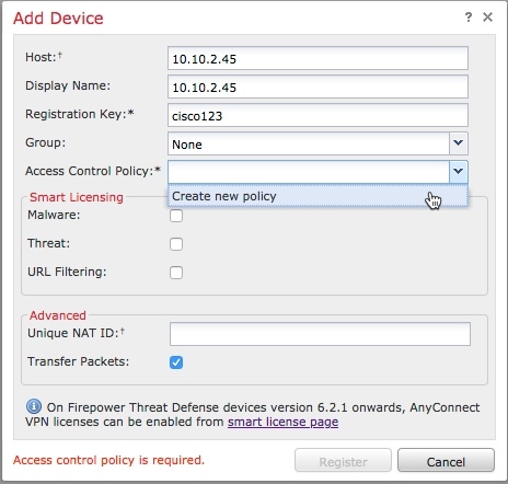
From the Access Control Policy list, click Create New Policy.

Step 4

In the New Policy dialog box, enter a name and, optionally, a description for the policy and click Block All Traffic as the following figure shows. (You'll change the default policy action later.)
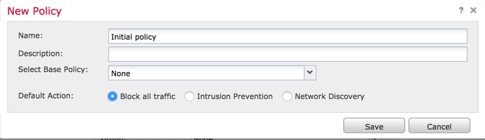
Step 5

Click Save.

Step 6

In the Add Device dialog box, check all the boxes in the Smart Licensing section.

Step 7

Check Transfer Packets.
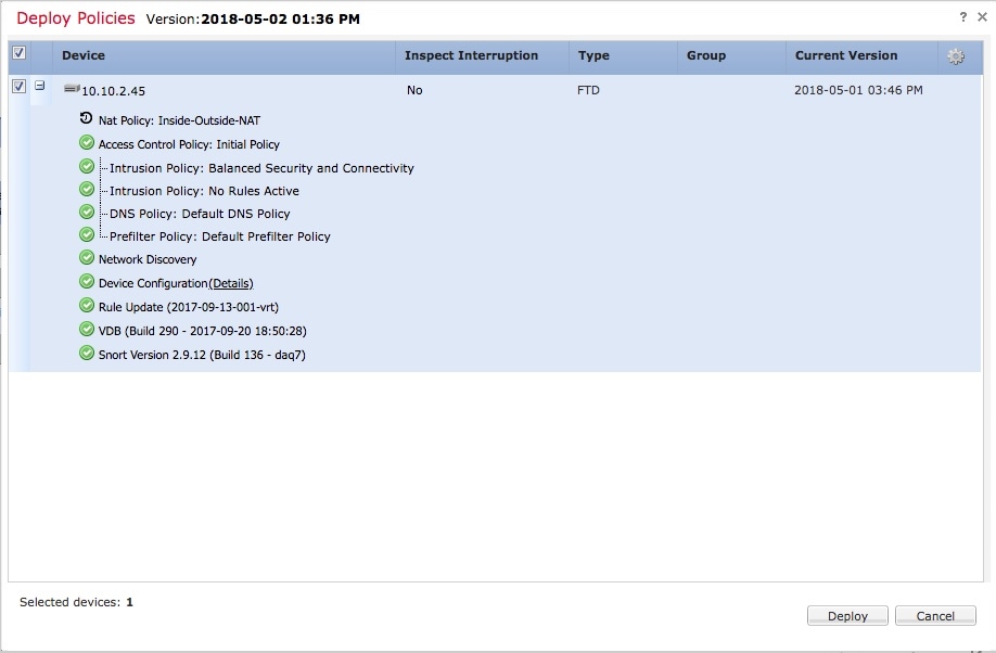
Step 8

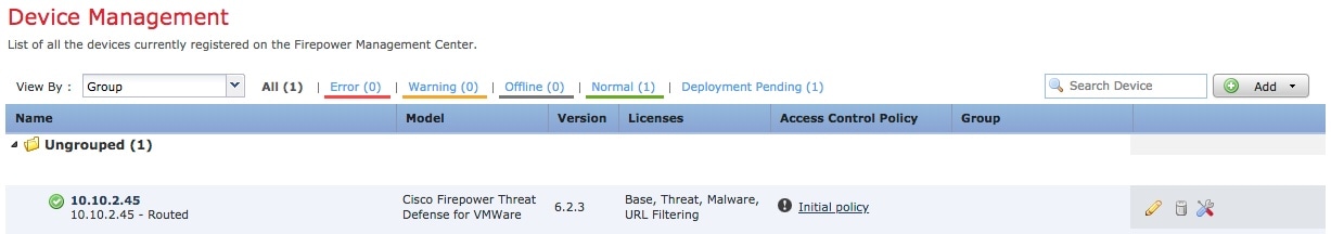
Click Register and wait for device discovery and registration to complete.

The following page is displayed after the device has been added.


What to do next

See Configure Managed Device Interfaces.

Configure Managed Device Interfaces

This task shows how to configure the managed device's inside and outside interfaces with IP addresses and subnet masks. Refer to the sample network diagram About the Network Setup.

Before you begin

See Configure Managed Device Interfaces.

Procedure


Step 1

In the Firepower Management Center, click Devices > Device Management.

Step 2

Click (edit) next to your managed device.

The Interfaces tab page is displayed.
Step 3

Click (edit) next to GigabitEthernet0/0 to configure the inside interface.

Step 4

From the Mode list, click None.

Step 5

Check Enabled.

Step 6

In the Name field, enter inside.

Step 7

From the Security Zone list, click New.

Step 8

In the New Security Zone dialog box, enter insidezone and click OK.

Step 9

Click the IPv4 tab.

Step 10

From the IP Type list, click Use Static IP.

Step 11

In the IP Address field, enter 10.10.1.1/24.

The following figure shows an example.

Step 12

Click OK.

Step 13

Repeat these tasks to configure the remaining interface as follows:

  1. Name: outside

    Interface: GigabitEthernet0/1

    Security Zone: outsidezone

    IPv4 Address: 209.165.200.255/16

Note 

Depending on what type of device you're managing, the interfaces might be identified differently than the preceding. For example, a virtual managed device has interfaces numbered GigabitEthernet0/0, GigabitEthernet0/1, and so on. A Firepower Threat Defense 4100 or 9300 series device has interfaces numbered Ethernet1/1, Ethernet2/1, Ethernet3/1, and so on.

Step 14

At the top of the page, click Save.

Your interfaces should be displayed as follows:


What to do next

See Add Static Routes.

Add Static Routes

A static route is a one-hop route that causes network traffic to go directly to a mapped resource; in this case, the outside gateway. We recommend setting up a static route in a simple network such as this.

For more information about static and dynamic routing, see Supported Route Types.

Procedure


Step 1

In the Firepower Management Center, click Devices > Device Management.

Step 2

Click (edit) next to your managed device.

Step 3

Click the Routing tab.

Step 4

Click Static Route.

Step 5

Click Add Route.

Step 6

Enter the following information in the Add Static Route Configuration dialog box:

Interface
Click outside.
Available Network
Add any-ipv4 to Selected Networks
Gateway
Click (add) and Name the gateway outsidegateway with a Network value of 209.165.200.254.

The following figure shows an example.

Step 7

Click OK.

Step 8

At the top of the page, click Save.


What to do next

See Add a NAT Policy.

Add a NAT Policy

The managed device uses NAT to enable communication between internal, non-routable IP addresses (like 10.10.2.1) and the internet. Routable, public IP addresses are scarce; without NAT, you would be severely restricted in the IP addresses you could use. The NAT policy you set up in this task forwards packets from the inside interface to the outside interface.

For more information about NAT, see Why Use NAT?

Procedure


Step 1

In the Firepower Management Center, click Devices > NAT.

Step 2

Click New Policy > Threat Defense NAT.

Step 3

In the New Policy dialog box, enter the following information:

Name
Enter Inside-Outside-NAT
Description
Enter an optional description.
Selected Devices
Add 10.10.2.45 to Selected Devices.
Step 4

Click Save.

Step 5

After the page refreshes, click Add Rule.

Step 6

Click the Interface Objects tab.

Step 7

Add the security zones you created earlier as source and destination interface objects as follows:

Step 8

Click the Translation tab.

Step 9

Click (Add) next to Original Source.

Step 10

In the New Network Objects dialog box, enter the following information:

Name
Enter insidesubnet
Description
Enter an optional description.
Network
Enter 10.10.2.0/24
Step 11

From the Translated Source list, click Destination Interface IP.

The following figure shows an example Add NAT Rule dialog box.

Step 12

Click OK.

Step 13

At the top of the page, click Save.

Step 14

Deploy your changes.

  1. At the top of the page, click Deploy.

  2. Optional. Expand the device to display the changes you're about to make.

  3. Check the box to the left of the device.

    The following figure shows an example.

  4. Click Deploy.

  5. Wait while the changes are deployed; deployment can take several minutes. Messages are displayed to indicate the progress of the deployment.


What to do next

See Test the System.