Features
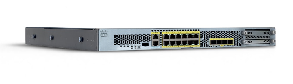
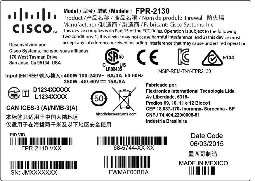
The Cisco Firepower 2100 series security appliance is a standalone modular security services platform. The series includes the Firepower 2110, 2120, 2130, and 2140. See Product ID Numbers for a list of the product IDs (PIDs) associated with the 2100 series.
The Firepower 2100 series supports Cisco Firepower Threat Defense and Cisco ASA software. See the Cisco Firepower Compatibility Guide and the Cisco ASA Compatibility guide, which provide Cisco software and hardware compatibility, including operating system and hosting environment requirements, for each supported version.
 Note |
Threat Defense Version 7.4 and ASA Version 9.20 are the final supported software versions for the Firepower 2100 series. |

The following table lists the features for the Firepower 2100 series.
|
Feature |
2110 |
2120 |
2130 |
2140 |
||||
|---|---|---|---|---|---|---|---|---|
|
Form factor |
1 RU Fits a standard 19-inch (48.3-cm) square-hole rack |
|||||||
|
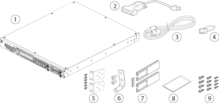
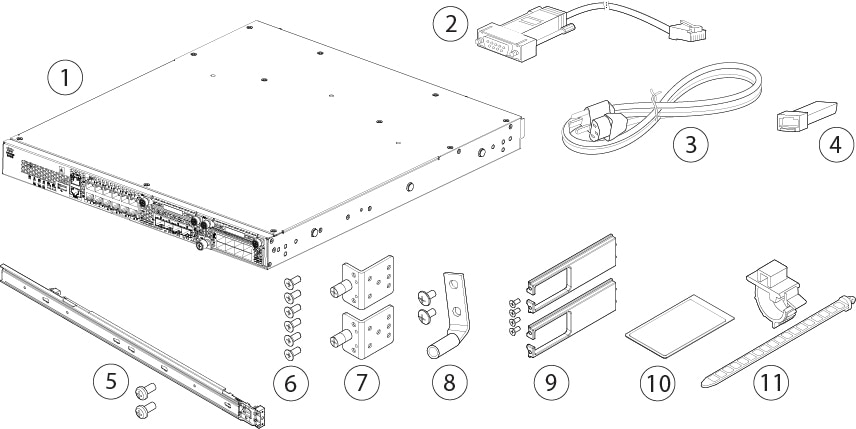
Rack mount |
Two 2-post mount brackets (Optional) 4-post Electronic Industries Association (EIA)-310-D rack |
4-post EIA-310-D rack (Optional) Two 2-post mount brackets |
||||||
|
Airflow |
Front to rear Cold aisle (front panel) to hot aisle (I/O side) |
|||||||
|
System memory |
16 GB |
32 GB |
64 GB |
|||||
|
Cavium NPU RAM |
8 G |
16G |
||||||
|
Flash |
8 G (nominal) |
|||||||
|
Maximum number of interfaces |
16 |
24 |
||||||
|
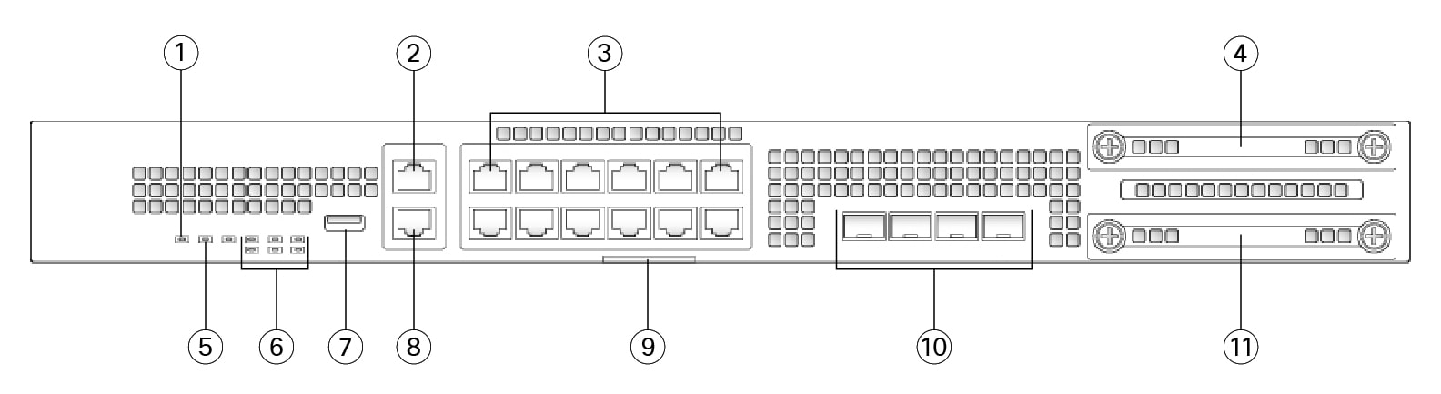
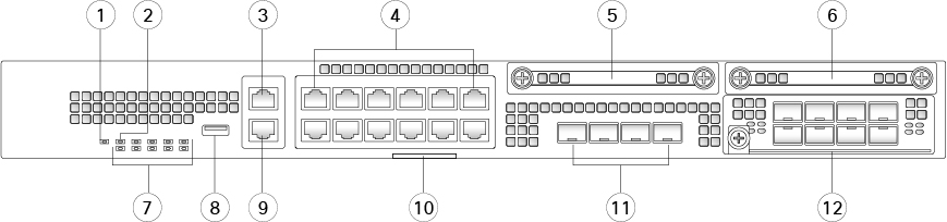
Management port |
1 Gigabit Ethernet (10 M/100 M/1 G Base-T) |
|||||||
|
Console port |
One Cisco Serial (RS-232 on RJ-45) |
|||||||
|
USB port |
USB 2.0 Type A (500 mA) |
|||||||
|
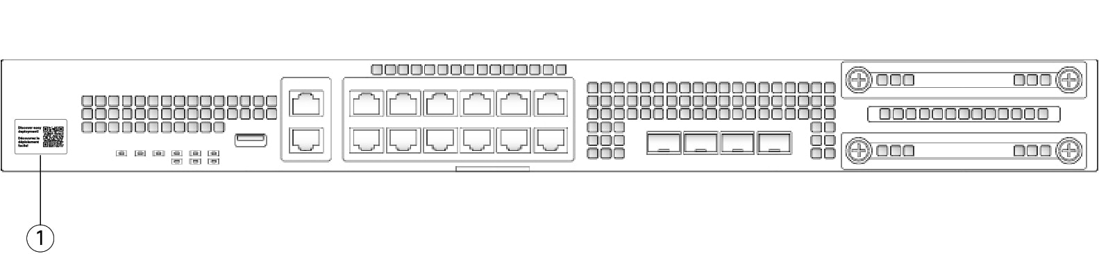
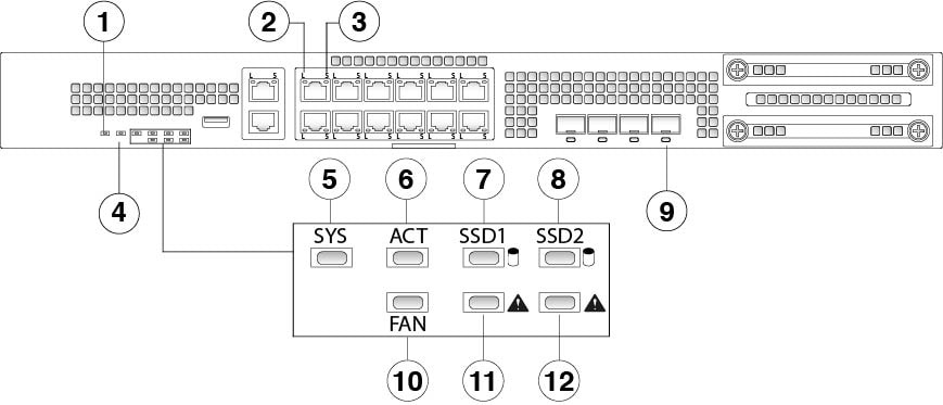
Network ports |
12 fixed RJ-45 1 G/100 M/10 M ports (named Ethernet 1/1 through 1/12 ) |
|||||||
|
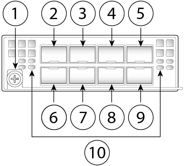
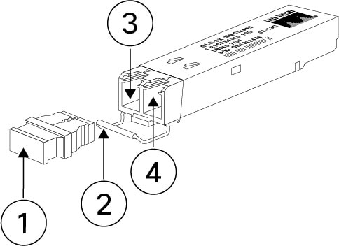
Small form-factor pluggable (SFP) ports |
Four fixed 1-Gbps SFP ports |
Four fixed 1/10-Gbps SFP+ ports |
||||||
|
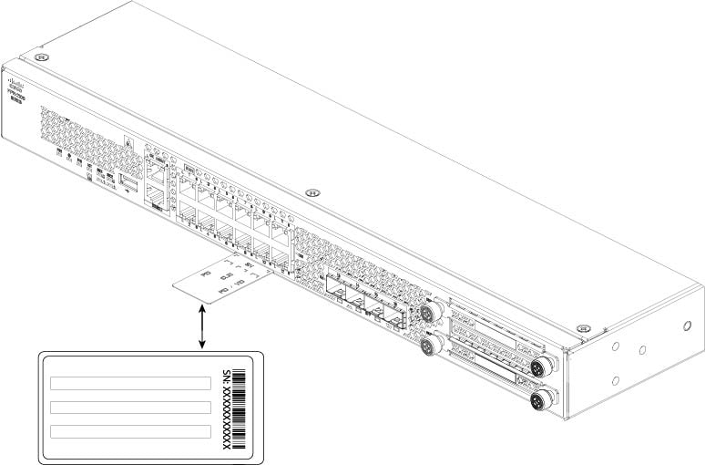
Pullout asset card |
Displays serial number |
|||||||
|
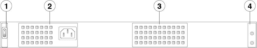
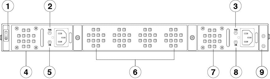
Grounding lug |
On rear panel |
|||||||
|
Locator beacon |
On front panel |
|||||||
|
Power switch |
On rear panel |
|||||||
|
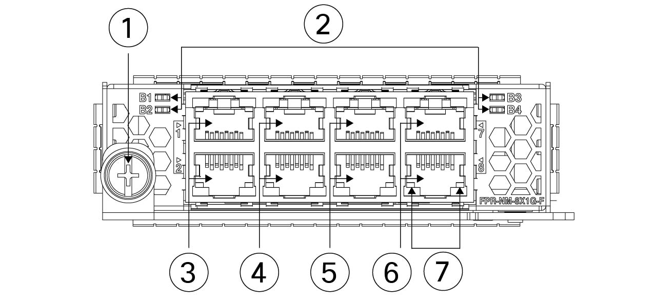
Network module slots |
No |
One Not hot-swappable |
||||||
|
Network modules |
— |
|
||||||
|
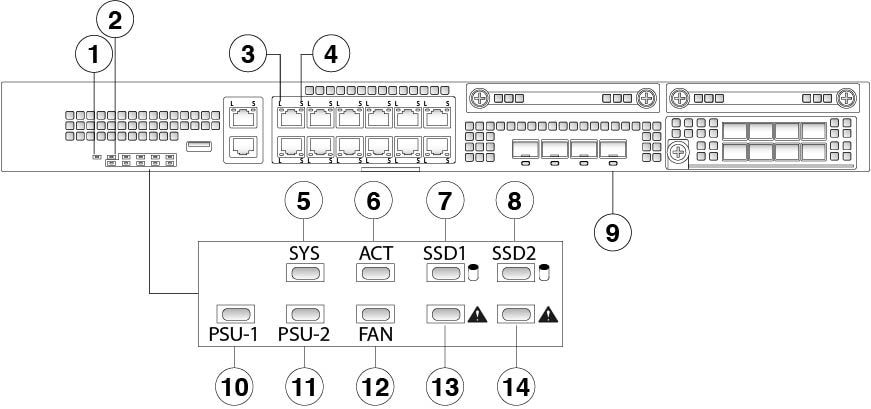
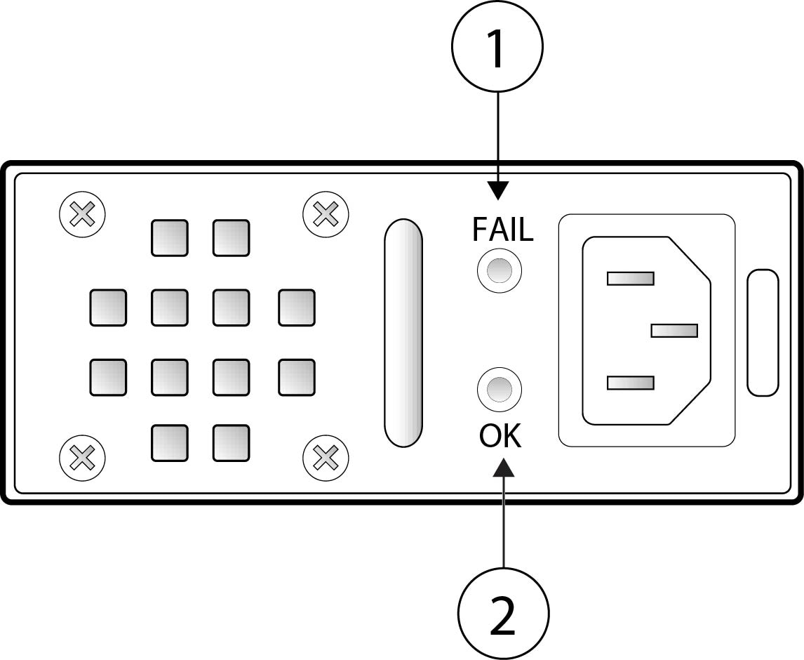
AC power supply |
One fixed AC power supply module |
Two power supply slots Ships with one 400-W AC power supply module Hot-swappable |
Two power supply slots Ships with two 400-W AC power supply modules Hot-swappable |
|||||
|
DC power supply |
No |
Yes (optional) |
||||||
|
Redundant power |
No |
Yes |
||||||
|
Fan |
Two fixed fans Internal component only; not field-replaceable |
One hot-swappable fan tray with four fans |
||||||
|
Storage |
Two SSD slots (100 GB ) Ships with one 100-GB SSD installed in slot 1
Slot 2 is reserved for the Malware Storage Pack (MSP). |
Two SSD slots (200 GB ) Ships with one 200-GB SSD installed in slot 1
Slot 2 is reserved for the MSP. |
||||||
|
MSP |
Installed in SSD slot 2 |
|||||||
|
Network Equipment Building Systems (NEBS) certification |
— |
— |
Certified |
— |
||||


 Feedback