Overview
Proposed architecture:
The architecture proposed and described in this document is for demonstration. The local network engineer should be consulted before applying the parameters used in this document. IP addresses, port numbers and VLAN IDs used should be verified beforehand as wrong configurations could stop normal exchanges and stop the process.
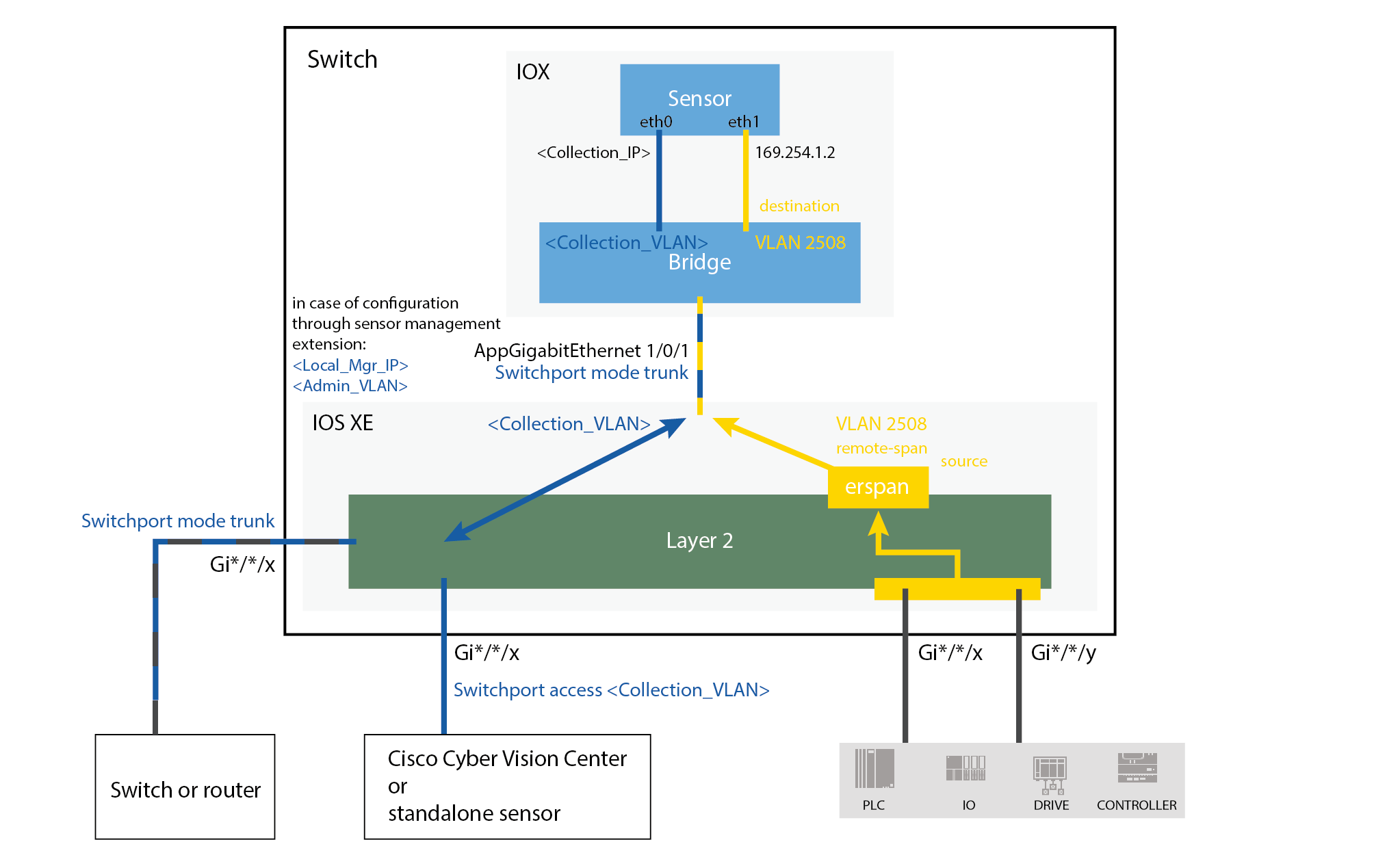
The schema below explains the architecture virtually deployed in the switch to embed the sensor application. VLAN and physical ports configuration will allow OT traffic to be copied and communication with the Cisco Cyber Vision Center to be established.
The communication between the Cisco Cyber Vision Center and the sensor is represented in blue on the schema. Mirrored OT traffic is represented in yellow.
The architecture in this document is meant for a switch with an embedded sensor directly connected to the Cisco Cyber Vision Center. The schema presents two types of architecture:
-
one with a direct connection to the Center (link="switchport access vlan 507").
-
the other with a trunk to another switch or router which is connected to the Center (link="switch mode trunk").
Several types of installation are explained. One of them is the installation with the Sensor Management extension. This method requires an access for the Cisco Cyber Vision Center to the switch's Local Manager. Several solutions exist:
having the Center on the same subnet than the switch's Local Manager (<admin_VLAN> and <collection_VLAN> are the same).
having a route path from the Center to an <admin_VLAN> that is different from <collection_VLAN>.
Any port of the switch can be used for the communication with the Center or for OT traffic.
Architecture diagram for:
-
Cisco Catalyst IE3300 10G Rugged Series Switch
-
Cisco Catalyst IE3400 Rugged Series Switch
-
Cisco Catalyst IE3400 Heavy Duty Series Switch

Architecture diagram for:
-
Cisco Catalyst 9300 Series Switch
-
Cisco Catalyst 9400 Series Switch
-
Cisco Catalyst IE9300 Rugged Series Switch
 Feedback