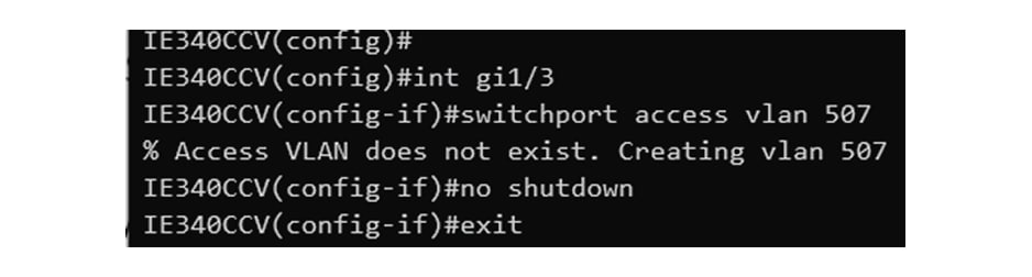
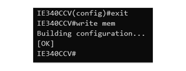
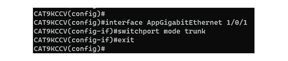
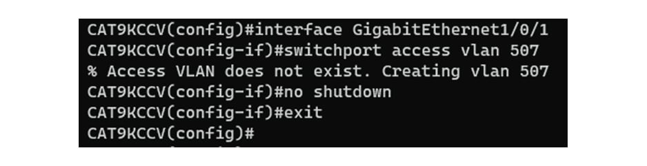
Configure the switch access
To configure each Cisco switch access refer to its corresponding installation guide available through the following links:
-
Cisco Catalyst IE3x00:
https://www.cisco.com/c/en/us/support/switches/catalyst-ie3400-heavy-duty-series/series.html
-
Cisco Catalyst IE9x00:
https://www.cisco.com/c/en/us/support/switches/catalyst-ie9300-rugged-series/series.html
-
Cisco Catalyst 9x00:


 Feedback