- Information About the Firewall Mode
- Information About Routed Firewall Mode
- Information About Transparent Firewall Mode
- Using the Transparent Firewall in Your Network
- Bridge Groups
- Management Interface (ASA 5512-X and Higher)
- Allowing Layer 3 Traffic
- Allowed MAC Addresses
- Passing Traffic Not Allowed in Routed Mode
- Passing Traffic For Routed-Mode Features
- BPDU Handling
- MAC Address vs. Route Lookups
- ARP Inspection
- MAC Address Table
Transparent or Routed Firewall Mode
This chapter describes how to set the firewall mode to routed or transparent, as well as how the firewall works in each firewall mode. This chapter also includes information about customizing the transparent firewall operation.
You can set the firewall mode independently for each context in multiple context mode.
- Information About the Firewall Mode
- Licensing Requirements for the Firewall Mode
- Default Settings
- Guidelines and Limitations
- Setting the Firewall Mode (Single Mode)
- Configuring ARP Inspection for the Transparent Firewall
- Customizing the MAC Address Table for the Transparent Firewall
- Firewall Mode Examples
- Feature History for the Firewall Mode
Information About the Firewall Mode
Information About Routed Firewall Mode
In routed mode, the ASA is considered to be a router hop in the network. Routed mode supports many interfaces. Each interface is on a different subnet. You can share interfaces between contexts.
The ASA acts as a router between connected networks, and each interface requires an IP address on a different subnet. The ASA supports multiple dynamic routing protocols. However, we recommend using the advanced routing capabilities of the upstream and downstream routers instead of relying on the ASA for extensive routing needs.
Information About Transparent Firewall Mode
Traditionally, a firewall is a routed hop and acts as a default gateway for hosts that connect to one of its screened subnets. A transparent firewall, on the other hand, is a Layer 2 firewall that acts like a “bump in the wire,” or a “stealth firewall,” and is not seen as a router hop to connected devices.
Using the Transparent Firewall in Your Network
The ASA connects the same network between its interfaces. Because the firewall is not a routed hop, you can easily introduce a transparent firewall into an existing network.
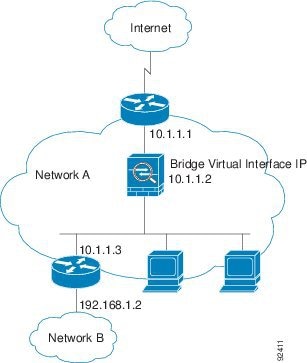
Figure 7-1 shows a typical transparent firewall network where the outside devices are on the same subnet as the inside devices. The inside router and hosts appear to be directly connected to the outside router.
Figure 7-1 Transparent Firewall Network
Bridge Groups
If you do not want the overhead of security contexts, or want to maximize your use of security contexts, you can group interfaces together in a bridge group, and then configure multiple bridge groups, one for each network. Bridge group traffic is isolated from other bridge groups; traffic is not routed to another bridge group within the ASA, and traffic must exit the ASA before it is routed by an external router back to another bridge group in the ASA. Although the bridging functions are separate for each bridge group, many other functions are shared between all bridge groups. For example, all bridge groups share a syslog server or AAA server configuration. For complete security policy separation, use security contexts with one bridge group in each context.
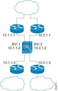
Figure 7-2 shows two networks connected to the ASA, which has two bridge groups.
Figure 7-2 Transparent Firewall Network with Two Bridge Groups

Note![]() Each bridge group requires a management IP address. The ASA uses this IP address as the source address for packets originating from the bridge group. The management IP address must be on the same subnet as the connected network. For another method of management, see Management Interface (ASA 5512-X and Higher).
Each bridge group requires a management IP address. The ASA uses this IP address as the source address for packets originating from the bridge group. The management IP address must be on the same subnet as the connected network. For another method of management, see Management Interface (ASA 5512-X and Higher).
The ASA does not support traffic on secondary networks; only traffic on the same network as the management IP address is supported.
Management Interface (ASA 5512-X and Higher)
In addition to each bridge group management IP address, you can add a separate Management slot / port interface that is not part of any bridge group, and that allows only management traffic to the ASA. For more information, see Management Interface.
Allowing Layer 3 Traffic
- Unicast IPv4 and IPv6 traffic is allowed through the transparent firewall automatically from a higher security interface to a lower security interface, without an ACL.
Note![]() Broadcast and multicast traffic can be passed using access rules. See the firewall configuration guide for more information.
Broadcast and multicast traffic can be passed using access rules. See the firewall configuration guide for more information.
- ARPs are allowed through the transparent firewall in both directions without an ACL. ARP traffic can be controlled by ARP inspection.
- For Layer 3 traffic travelling from a low to a high security interface, an extended ACL is required on the low security interface. See the firewall configuration guide for more information.
Allowed MAC Addresses
The following destination MAC addresses are allowed through the transparent firewall. Any MAC address not on this list is dropped.
- TRUE broadcast destination MAC address equal to FFFF.FFFF.FFFF
- IPv4 multicast MAC addresses from 0100.5E00.0000 to 0100.5EFE.FFFF
- IPv6 multicast MAC addresses from 3333.0000.0000 to 3333.FFFF.FFFF
- BPDU multicast address equal to 0100.0CCC.CCCD
- AppleTalk multicast MAC addresses from 0900.0700.0000 to 0900.07FF.FFFF
Passing Traffic Not Allowed in Routed Mode
In routed mode, some types of traffic cannot pass through the ASA even if you allow it in an ACL. The transparent firewall, however, can allow almost any traffic through using either an extended ACL (for IP traffic) or an EtherType ACL (for non-IP traffic).
Non-IP traffic (for example AppleTalk, IPX, BPDUs, and MPLS) can be configured to go through using an EtherType ACL.
Note![]() The transparent mode ASA does not pass CDP packets packets, or any packets that do not have a valid EtherType greater than or equal to 0x600. An exception is made for BPDUs and IS-IS, which are supported.
The transparent mode ASA does not pass CDP packets packets, or any packets that do not have a valid EtherType greater than or equal to 0x600. An exception is made for BPDUs and IS-IS, which are supported.
Passing Traffic For Routed-Mode Features
For features that are not directly supported on the transparent firewall, you can allow traffic to pass through so that upstream and downstream routers can support the functionality. For example, by using an extended ACL, you can allow DHCP traffic (instead of the unsupported DHCP relay feature) or multicast traffic such as that created by IP/TV. You can also establish routing protocol adjacencies through a transparent firewall; you can allow OSPF, RIP, EIGRP, or BGP traffic through based on an extended ACL. Likewise, protocols like HSRP or VRRP can pass through the ASA.
BPDU Handling
To prevent loops using the Spanning Tree Protocol, BPDUs are passed by default. To block BPDUs, you need to configure an EtherType ACL to deny them. If you are using failover, you might want to block BPDUs to prevent the switch port from going into a blocking state when the topology changes. See Transparent Firewall Mode Requirements for more information.
MAC Address vs. Route Lookups
When the ASA runs in transparent mode, the outgoing interface of a packet is determined by performing a MAC address lookup instead of a route lookup.
Route lookups, however, are necessary for the following traffic types:
- Traffic originating on the ASA—For example, if your syslog server is located on a remote network, you must use a static route so the ASA can reach that subnet.
- Traffic that is at least one hop away from the ASA with NAT enabled—The ASA needs to perform a route lookup to find the next hop gateway; you need to add a static route on the ASA for the real host address.
- Voice over IP (VoIP) and DNS traffic with inspection enabled, and the endpoint is at least one hop away from the ASA—For example, if you use the transparent firewall between a CCM and an H.323 gateway, and there is a router between the transparent firewall and the H.323 gateway, then you need to add a static route on the ASA for the H.323 gateway for successful call completion. If you enable NAT for the inspected traffic, a static route is required to determine the egress interface for the real host address that is embedded in the packet. Affected applications include:
ARP Inspection
By default, all ARP packets are allowed through the ASA. You can control the flow of ARP packets by enabling ARP inspection.
When you enable ARP inspection, the ASA compares the MAC address, IP address, and source interface in all ARP packets to static entries in the ARP table, and takes the following actions:
- If the IP address, MAC address, and source interface match an ARP entry, the packet is passed through.
- If there is a mismatch between the MAC address, the IP address, or the interface, then the ASA drops the packet.
- If the ARP packet does not match any entries in the static ARP table, then you can set the ASA to either forward the packet out all interfaces (flood), or to drop the packet.
Note![]() The dedicated management interface, if present, never floods packets even if this parameter is set to flood.
The dedicated management interface, if present, never floods packets even if this parameter is set to flood.
ARP inspection prevents malicious users from impersonating other hosts or routers (known as ARP spoofing). ARP spoofing can enable a “man-in-the-middle” attack. For example, a host sends an ARP request to the gateway router; the gateway router responds with the gateway router MAC address. The attacker, however, sends another ARP response to the host with the attacker MAC address instead of the router MAC address. The attacker can now intercept all the host traffic before forwarding it on to the router.
ARP inspection ensures that an attacker cannot send an ARP response with the attacker MAC address, so long as the correct MAC address and the associated IP address are in the static ARP table.
MAC Address Table
The ASA learns and builds a MAC address table in a similar way as a normal bridge or switch: when a device sends a packet through the ASA, the ASA adds the MAC address to its table. The table associates the MAC address with the source interface so that the ASA knows to send any packets addressed to the device out the correct interface.
The ASA 5505 includes a built-in switch; the switch MAC address table maintains the MAC address-to-switch port mapping for traffic within each VLAN. This section only discusses the bridge MAC address table, which maintains the MAC address-to-VLAN interface mapping for traffic that passes between VLANs.
Because the ASA is a firewall, if the destination MAC address of a packet is not in the table, the ASA does not flood the original packet on all interfaces as a normal bridge does. Instead, it generates the following packets for directly connected devices or for remote devices:
- Packets for directly connected devices—The ASA generates an ARP request for the destination IP address, so that the ASA can learn which interface receives the ARP response.
- Packets for remote devices—The ASA generates a ping to the destination IP address so that the ASA can learn which interface receives the ping reply.
Licensing Requirements for the Firewall Mode
The following table shows the licensing requirements for this feature.
|
|
|
|---|---|
Default Settings
The default mode is routed mode.
- By default, all ARP packets are allowed through the ASA.
- If you enable ARP inspection, the default setting is to flood non-matching packets.
- The default timeout value for dynamic MAC address table entries is 5 minutes.
- By default, each interface automatically learns the MAC addresses of entering traffic, and the ASA adds corresponding entries to the MAC address table.
Guidelines and Limitations
Set the firewall mode per context.
Transparent Firewall Guidelines
- In transparent firewall mode, the management interface updates the MAC address table in the same manner as a data interface; therefore you should not connect both a management and a data interface to the same switch unless you configure one of the switch ports as a routed port (by default Cisco Catalyst switches share a MAC address for all VLAN switch ports). Otherwise, if traffic arrives on the management interface from the physically-connected switch, then the ASA updates the MAC address table to use the management interface to access the switch, instead of the data interface. This action causes a temporary traffic interruption; the ASA will not re-update the MAC address table for packets from the switch to the data interface for at least 30 seconds for security reasons.
- Each directly-connected network must be on the same subnet.
- Do not specify the bridge group management IP address as the default gateway for connected devices; devices need to specify the router on the other side of the ASA as the default gateway.
- The default route for the transparent firewall, which is required to provide a return path for management traffic, is only applied to management traffic from one bridge group network. This is because the default route specifies an interface in the bridge group as well as the router IP address on the bridge group network, and you can only define one default route. If you have management traffic from more than one bridge group network, you need to specify a static route that identifies the network from which you expect management traffic.
See Guidelines and Limitations for more guidelines.
Additional Guidelines and Limitations
- When you change firewall modes, the ASA clears the running configuration because many commands are not supported for both modes. The startup configuration remains unchanged. If you reload without saving, then the startup configuration is loaded, and the mode reverts back to the original setting. See Setting the Firewall Mode (Single Mode) for information about backing up your configuration file.
- If you download a text configuration to the ASA that changes the mode with the firewall transparent command, be sure to put the command at the top of the configuration; the ASA changes the mode as soon as it reads the command and then continues reading the configuration you downloaded. If the command appears later in the configuration, the ASA clears all the preceding lines in the configuration.
Unsupported Features in Transparent Mode
Table 7-1 lists the features are not supported in transparent mode.
Setting the Firewall Mode (Single Mode)
This section describes how to change the firewall mode using the CLI. For single mode and for the currently connected context in multiple mode (typically the admin context), you cannot change the mode in ASDM. For other multiple mode contexts, you can set the mode in ASDM for each context; see Configuring a Security Context.
Note![]() We recommend that you set the firewall mode before you perform any other configuration because changing the firewall mode clears the running configuration.
We recommend that you set the firewall mode before you perform any other configuration because changing the firewall mode clears the running configuration.
Prerequisites
When you change modes, the ASA clears the running configuration (see Guidelines and Limitations for more information).
- If you already have a populated configuration, be sure to back up your configuration before changing the mode; you can use this backup for reference when creating your new configuration.
- Use the CLI at the console port to change the mode. If you use any other type of session, including the ASDM Command Line Interface tool or SSH, you will be disconnected when the configuration is cleared, and you will have to reconnect to the ASA using the console port in any case.
- Set the mode within the context.
Detailed Steps
Note![]() To set the firewall mode to transparent and also configure ASDM management access after the configuration is cleared, see Customizing ASDM Access (ASA 5505) or Customizing ASDM Access (ASA 5512-X and Higher, ASAv).
To set the firewall mode to transparent and also configure ASDM management access after the configuration is cleared, see Customizing ASDM Access (ASA 5505) or Customizing ASDM Access (ASA 5512-X and Higher, ASAv).
Configuring ARP Inspection for the Transparent Firewall
This section describes how to configure ARP inspection and includes the following topics:
Task Flow for Configuring ARP Inspection
To configure ARP Inspection, perform the following steps:
Step 1![]() Add static ARP entries according to the Adding a Static ARP Entry. ARP inspection compares ARP packets with static ARP entries in the ARP table, so static ARP entries are required for this feature.
Add static ARP entries according to the Adding a Static ARP Entry. ARP inspection compares ARP packets with static ARP entries in the ARP table, so static ARP entries are required for this feature.
Step 2![]() Enable ARP inspection according to the Enabling ARP Inspection.
Enable ARP inspection according to the Enabling ARP Inspection.
Adding a Static ARP Entry
ARP inspection compares ARP packets with static ARP entries in the ARP table. Although hosts identify a packet destination by an IP address, the actual delivery of the packet on Ethernet relies on the Ethernet MAC address. When a router or host wants to deliver a packet on a directly connected network, it sends an ARP request asking for the MAC address associated with the IP address, and then delivers the packet to the MAC address according to the ARP response. The host or router keeps an ARP table so it does not have to send ARP requests for every packet it needs to deliver. The ARP table is dynamically updated whenever ARP responses are sent on the network, and if an entry is not used for a period of time, it times out. If an entry is incorrect (for example, the MAC address changes for a given IP address), the entry times out before it can be updated.
Note![]() The transparent firewall uses dynamic ARP entries in the ARP table for traffic to and from the ASA, such as management traffic.
The transparent firewall uses dynamic ARP entries in the ARP table for traffic to and from the ASA, such as management traffic.
Detailed Steps
Step 1![]() Choose the Configuration > Device Management > Advanced > ARP > ARP Static Table pane.
Choose the Configuration > Device Management > Advanced > ARP > ARP Static Table pane.
Step 2![]() (Optional) To set the ARP timeout for dynamic ARP entries, enter a value in the ARP Timeout field.
(Optional) To set the ARP timeout for dynamic ARP entries, enter a value in the ARP Timeout field.
This field sets the amount of time before the ASA rebuilds the ARP table, between 60 to 4294967 seconds. The default is 14400 seconds. Rebuilding the ARP table automatically updates new host information and removes old host information. You might want to reduce the timeout because the host information changes frequently.
Step 3![]() (Optional; 8.4(5) only) To allow non-connected subnets, check the Allow non-connected subnets check box. The ASA ARP cache only contains entries from directly-connected subnets by default. You can enable the ARP cache to also include non-directly-connected subnets. We do not recommend enabling this feature unless you know the security risks. This feature could facilitate denial of service (DoS) attack against the ASA; a user on any interface could send out many ARP replies and overload the ASA ARP table with false entries.
(Optional; 8.4(5) only) To allow non-connected subnets, check the Allow non-connected subnets check box. The ASA ARP cache only contains entries from directly-connected subnets by default. You can enable the ARP cache to also include non-directly-connected subnets. We do not recommend enabling this feature unless you know the security risks. This feature could facilitate denial of service (DoS) attack against the ASA; a user on any interface could send out many ARP replies and overload the ASA ARP table with false entries.
You may want to use this feature if you use:
The Add ARP Static Configuration dialog box appears.
Step 5![]() From the Interface drop-down list, choose the interface attached to the host network.
From the Interface drop-down list, choose the interface attached to the host network.
Step 6![]() In the IP Address field, enter the IP address of the host.
In the IP Address field, enter the IP address of the host.
Step 7![]() In the MAC Address field, enter the MAC address of the host; for example, 00e0.1e4e.3d8b.
In the MAC Address field, enter the MAC address of the host; for example, 00e0.1e4e.3d8b.
Step 8![]() To perform proxy ARP for this address, check the Proxy ARP check box.
To perform proxy ARP for this address, check the Proxy ARP check box.
If the ASA receives an ARP request for the specified IP address, then it responds with the specified MAC address.
Step 9![]() Click OK, and then Apply.
Click OK, and then Apply.
What to Do Next
Enable ARP inspection according to the Enabling ARP Inspection.
Enabling ARP Inspection
Detailed Steps
Step 1![]() Choose the Configuration > Device Management > Advanced > ARP > ARP Inspection pane.
Choose the Configuration > Device Management > Advanced > ARP > ARP Inspection pane.
Step 2![]() Choose the interface row on which you want to enable ARP inspection, and click Edit.
Choose the interface row on which you want to enable ARP inspection, and click Edit.
The Edit ARP Inspection dialog box appears.
Step 3![]() To enable ARP inspection, check the Enable ARP Inspection check box.
To enable ARP inspection, check the Enable ARP Inspection check box.
Step 4![]() (Optional) To flood non-matching ARP packets, check the Flood ARP Packets check box.
(Optional) To flood non-matching ARP packets, check the Flood ARP Packets check box.
By default, packets that do not match any element of a static ARP entry are flooded out all interfaces except the originating interface. If there is a mismatch between the MAC address, the IP address, or the interface, then the ASA drops the packet.
If you uncheck this check box, all non-matching packets are dropped, which restricts ARP through the ASA to only static entries.
Note![]() The Management 0/0 or 0/1 interface or subinterface, if present, never floods packets even if this parameter is set to flood.
The Management 0/0 or 0/1 interface or subinterface, if present, never floods packets even if this parameter is set to flood.
Step 5![]() Click OK, and then Apply.
Click OK, and then Apply.
Customizing the MAC Address Table for the Transparent Firewall
This section describes how you can customize the MAC address table and includes the following sections:
Adding a Static MAC Address
Normally, MAC addresses are added to the MAC address table dynamically as traffic from a particular MAC address enters an interface. You can add static MAC addresses to the MAC address table if desired. One benefit to adding static entries is to guard against MAC spoofing. If a client with the same MAC address as a static entry attempts to send traffic to an interface that does not match the static entry, then the ASA drops the traffic and generates a system message. When you add a static ARP entry (see Adding a Static ARP Entry), a static MAC address entry is automatically added to the MAC address table.
To add a static MAC address to the MAC address table, perform the following steps:
Step 1![]() Choose the Configuration > Device Setup > Bridging > MAC Address Table pane.
Choose the Configuration > Device Setup > Bridging > MAC Address Table pane.
Step 2![]() (Optional) To set the time a MAC address entry stays in the MAC address table before timing out, enter a value in the Dynamic Entry Timeout field.
(Optional) To set the time a MAC address entry stays in the MAC address table before timing out, enter a value in the Dynamic Entry Timeout field.
This value is between 5 and 720 minutes (12 hours). 5 minutes is the default.
The Add MAC Address Entry dialog box appears.
Step 4![]() From the Interface Name drop-down list, choose the source interface associated with the MAC address.
From the Interface Name drop-down list, choose the source interface associated with the MAC address.
Step 5![]() In the MAC Address field, enter the MAC address.
In the MAC Address field, enter the MAC address.
Step 6![]() Click OK, and then Apply.
Click OK, and then Apply.
Disabling MAC Address Learning
By default, each interface automatically learns the MAC addresses of entering traffic, and the ASA adds corresponding entries to the MAC address table. You can disable MAC address learning if desired, however, unless you statically add MAC addresses to the table, no traffic can pass through the ASA.
To disable MAC address learning, perform the following steps:
Step 1![]() Choose the Configuration > Device Setup > Bridging > MAC Learning pane.
Choose the Configuration > Device Setup > Bridging > MAC Learning pane.
Step 2![]() To disable MAC learning, choose an interface row, and click Disable.
To disable MAC learning, choose an interface row, and click Disable.
Step 3![]() To reenable MAC learning, click Enable.
To reenable MAC learning, click Enable.
Firewall Mode Examples
This section includes examples of how traffic moves through the ASA and includes the following topics:
- How Data Moves Through the ASA in Routed Firewall Mode
- How Data Moves Through the Transparent Firewall
How Data Moves Through the ASA in Routed Firewall Mode
This section describes how data moves through the ASA in routed firewall mode and includes the following topics:
An Inside User Visits a Web Server
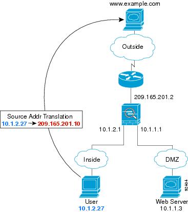
Figure 7-3 shows an inside user accessing an outside web server.
The following steps describe how data moves through the ASA (see Figure 7-3):
1.![]() The user on the inside network requests a web page from www.example.com.
The user on the inside network requests a web page from www.example.com.
2.![]() The ASA receives the packet and because it is a new session, the ASA verifies that the packet is allowed according to the terms of the security policy (access lists, filters, AAA).
The ASA receives the packet and because it is a new session, the ASA verifies that the packet is allowed according to the terms of the security policy (access lists, filters, AAA).
For multiple context mode, the ASA first classifies the packet to a context.
3.![]() The ASA translates the local source address (10.1.2.27) to the global address 209.165.201.10, which is on the outside interface subnet.
The ASA translates the local source address (10.1.2.27) to the global address 209.165.201.10, which is on the outside interface subnet.
The global address could be on any subnet, but routing is simplified when it is on the outside interface subnet.
4.![]() The ASA then records that a session is established and forwards the packet from the outside interface.
The ASA then records that a session is established and forwards the packet from the outside interface.
5.![]() When www.example.com responds to the request, the packet goes through the ASA, and because the session is already established, the packet bypasses the many lookups associated with a new connection. The ASA performs NAT by untranslating the global destination address to the local user address, 10.1.2.27.
When www.example.com responds to the request, the packet goes through the ASA, and because the session is already established, the packet bypasses the many lookups associated with a new connection. The ASA performs NAT by untranslating the global destination address to the local user address, 10.1.2.27.
An Outside User Visits a Web Server on the DMZ
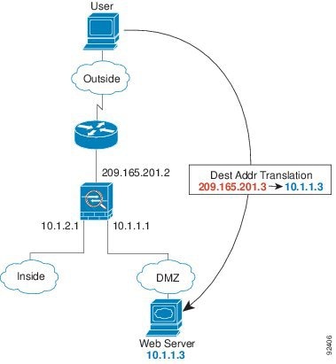
Figure 7-4 shows an outside user accessing the DMZ web server.
The following steps describe how data moves through the ASA (see Figure 7-4):
1.![]() A user on the outside network requests a web page from the DMZ web server using the global destination address of 209.165.201.3, which is on the outside interface subnet.
A user on the outside network requests a web page from the DMZ web server using the global destination address of 209.165.201.3, which is on the outside interface subnet.
2.![]() The ASA receives the packet and untranslates the destination address to the local address 10.1.1.3.
The ASA receives the packet and untranslates the destination address to the local address 10.1.1.3.
3.![]() Because it is a new session, the ASA verifies that the packet is allowed according to the terms of the security policy (access lists, filters, AAA).
Because it is a new session, the ASA verifies that the packet is allowed according to the terms of the security policy (access lists, filters, AAA).
For multiple context mode, the ASA first classifies the packet to a context.
4.![]() The ASA then adds a session entry to the fast path and forwards the packet from the DMZ interface.
The ASA then adds a session entry to the fast path and forwards the packet from the DMZ interface.
5.![]() When the DMZ web server responds to the request, the packet goes through the ASA and because the session is already established, the packet bypasses the many lookups associated with a new connection. The ASA performs NAT by translating the local source address to 209.165.201.3.
When the DMZ web server responds to the request, the packet goes through the ASA and because the session is already established, the packet bypasses the many lookups associated with a new connection. The ASA performs NAT by translating the local source address to 209.165.201.3.
An Inside User Visits a Web Server on the DMZ
Figure 7-5 shows an inside user accessing the DMZ web server.
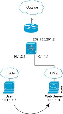
The following steps describe how data moves through the ASA (see Figure 7-5):
1.![]() A user on the inside network requests a web page from the DMZ web server using the destination address of 10.1.1.3.
A user on the inside network requests a web page from the DMZ web server using the destination address of 10.1.1.3.
2.![]() The ASA receives the packet and because it is a new session, the ASA verifies that the packet is allowed according to the terms of the security policy (access lists, filters, AAA).
The ASA receives the packet and because it is a new session, the ASA verifies that the packet is allowed according to the terms of the security policy (access lists, filters, AAA).
For multiple context mode, the ASA first classifies the packet to a context.
3.![]() The ASA then records that a session is established and forwards the packet out of the DMZ interface.
The ASA then records that a session is established and forwards the packet out of the DMZ interface.
4.![]() When the DMZ web server responds to the request, the packet goes through the fast path, which lets the packet bypass the many lookups associated with a new connection.
When the DMZ web server responds to the request, the packet goes through the fast path, which lets the packet bypass the many lookups associated with a new connection.
An Outside User Attempts to Access an Inside Host
Figure 7-6 shows an outside user attempting to access the inside network.
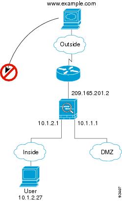
The following steps describe how data moves through the ASA (see Figure 7-6):
1.![]() A user on the outside network attempts to reach an inside host (assuming the host has a routable IP address).
A user on the outside network attempts to reach an inside host (assuming the host has a routable IP address).
If the inside network uses private addresses, no outside user can reach the inside network without NAT. The outside user might attempt to reach an inside user by using an existing NAT session.
2.![]() The ASA receives the packet and because it is a new session, the ASA verifies if the packet is allowed according to the security policy (access lists, filters, AAA).
The ASA receives the packet and because it is a new session, the ASA verifies if the packet is allowed according to the security policy (access lists, filters, AAA).
3.![]() The packet is denied, and the ASA drops the packet and logs the connection attempt.
The packet is denied, and the ASA drops the packet and logs the connection attempt.
If the outside user is attempting to attack the inside network, the ASA employs many technologies to determine if a packet is valid for an already established session.
A DMZ User Attempts to Access an Inside Host
Figure 7-7 shows a user in the DMZ attempting to access the inside network.
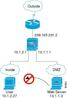
The following steps describe how data moves through the ASA (see Figure 7-7):
1.![]() A user on the DMZ network attempts to reach an inside host. Because the DMZ does not have to route the traffic on the Internet, the private addressing scheme does not prevent routing.
A user on the DMZ network attempts to reach an inside host. Because the DMZ does not have to route the traffic on the Internet, the private addressing scheme does not prevent routing.
2.![]() The ASA receives the packet and because it is a new session, the ASA verifies if the packet is allowed according to the security policy (access lists, filters, AAA).
The ASA receives the packet and because it is a new session, the ASA verifies if the packet is allowed according to the security policy (access lists, filters, AAA).
The packet is denied, and the ASA drops the packet and logs the connection attempt.
How Data Moves Through the Transparent Firewall
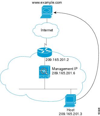
Figure 7-8 shows a typical transparent firewall implementation with an inside network that contains a public web server. The ASA has an access list so that the inside users can access Internet resources. Another access list lets the outside users access only the web server on the inside network.
Figure 7-8 Typical Transparent Firewall Data Path
This section describes how data moves through the ASA and includes the following topics:
An Inside User Visits a Web Server
Figure 7-9 shows an inside user accessing an outside web server.
The following steps describe how data moves through the ASA (see Figure 7-9):
1.![]() The user on the inside network requests a web page from www.example.com.
The user on the inside network requests a web page from www.example.com.
2.![]() The ASA receives the packet and adds the source MAC address to the MAC address table, if required. Because it is a new session, it verifies that the packet is allowed according to the terms of the security policy (access lists, filters, AAA).
The ASA receives the packet and adds the source MAC address to the MAC address table, if required. Because it is a new session, it verifies that the packet is allowed according to the terms of the security policy (access lists, filters, AAA).
For multiple context mode, the ASA first classifies the packet to a context.
3.![]() The ASA records that a session is established.
The ASA records that a session is established.
4.![]() If the destination MAC address is in its table, the ASA forwards the packet out of the outside interface. The destination MAC address is that of the upstream router, 209.165.201.2.
If the destination MAC address is in its table, the ASA forwards the packet out of the outside interface. The destination MAC address is that of the upstream router, 209.165.201.2.
If the destination MAC address is not in the ASA table, the ASA attempts to discover the MAC address by sending an ARP request or a ping. The first packet is dropped.
5.![]() The web server responds to the request; because the session is already established, the packet bypasses the many lookups associated with a new connection.
The web server responds to the request; because the session is already established, the packet bypasses the many lookups associated with a new connection.
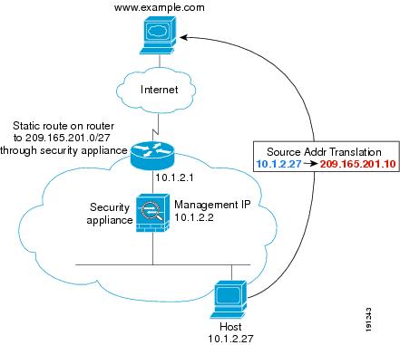
An Inside User Visits a Web Server Using NAT
Figure 7-10 shows an inside user accessing an outside web server.
Figure 7-10 Inside to Outside with NAT
The following steps describe how data moves through the ASA (see Figure 7-10):
1.![]() The user on the inside network requests a web page from www.example.com.
The user on the inside network requests a web page from www.example.com.
2.![]() The ASA receives the packet and adds the source MAC address to the MAC address table, if required. Because it is a new session, it verifies that the packet is allowed according to the terms of the security policy (access lists, filters, AAA).
The ASA receives the packet and adds the source MAC address to the MAC address table, if required. Because it is a new session, it verifies that the packet is allowed according to the terms of the security policy (access lists, filters, AAA).
For multiple context mode, the ASA first classifies the packet according to a unique interface.
3.![]() The ASA translates the real address (10.1.2.27) to the mapped address 209.165.201.10.
The ASA translates the real address (10.1.2.27) to the mapped address 209.165.201.10.
Because the mapped address is not on the same network as the outside interface, then be sure the upstream router has a static route to the mapped network that points to the ASA.
4.![]() The ASA then records that a session is established and forwards the packet from the outside interface.
The ASA then records that a session is established and forwards the packet from the outside interface.
5.![]() If the destination MAC address is in its table, the ASA forwards the packet out of the outside interface. The destination MAC address is that of the upstream router, 10.1.2.1.
If the destination MAC address is in its table, the ASA forwards the packet out of the outside interface. The destination MAC address is that of the upstream router, 10.1.2.1.
If the destination MAC address is not in the ASA table, the ASA attempts to discover the MAC address by sending an ARP request and a ping. The first packet is dropped.
6.![]() The web server responds to the request; because the session is already established, the packet bypasses the many lookups associated with a new connection.
The web server responds to the request; because the session is already established, the packet bypasses the many lookups associated with a new connection.
7.![]() The ASA performs NAT by untranslating the mapped address to the real address, 10.1.2.27.
The ASA performs NAT by untranslating the mapped address to the real address, 10.1.2.27.
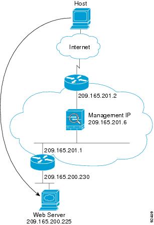
An Outside User Visits a Web Server on the Inside Network
Figure 7-11 shows an outside user accessing the inside web server.
The following steps describe how data moves through the ASA (see Figure 7-11):
1.![]() A user on the outside network requests a web page from the inside web server.
A user on the outside network requests a web page from the inside web server.
2.![]() The ASA receives the packet and adds the source MAC address to the MAC address table, if required. Because it is a new session, it verifies that the packet is allowed according to the terms of the security policy (access lists, filters, AAA).
The ASA receives the packet and adds the source MAC address to the MAC address table, if required. Because it is a new session, it verifies that the packet is allowed according to the terms of the security policy (access lists, filters, AAA).
For multiple context mode, the ASA first classifies the packet to a context.
3.![]() The ASA records that a session is established.
The ASA records that a session is established.
4.![]() If the destination MAC address is in its table, the ASA forwards the packet out of the inside interface. The destination MAC address is that of the downstream router, 209.165.201.1.
If the destination MAC address is in its table, the ASA forwards the packet out of the inside interface. The destination MAC address is that of the downstream router, 209.165.201.1.
If the destination MAC address is not in the ASA table, the ASA attempts to discover the MAC address by sending an ARP request and a ping. The first packet is dropped.
5.![]() The web server responds to the request; because the session is already established, the packet bypasses the many lookups associated with a new connection.
The web server responds to the request; because the session is already established, the packet bypasses the many lookups associated with a new connection.
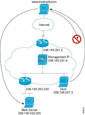
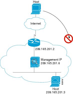
An Outside User Attempts to Access an Inside Host
Figure 7-12 shows an outside user attempting to access a host on the inside network.
The following steps describe how data moves through the ASA (see Figure 7-12):
1.![]() A user on the outside network attempts to reach an inside host.
A user on the outside network attempts to reach an inside host.
2.![]() The ASA receives the packet and adds the source MAC address to the MAC address table, if required. Because it is a new session, it verifies if the packet is allowed according to the terms of the security policy (access lists, filters, AAA).
The ASA receives the packet and adds the source MAC address to the MAC address table, if required. Because it is a new session, it verifies if the packet is allowed according to the terms of the security policy (access lists, filters, AAA).
For multiple context mode, the ASA first classifies the packet to a context.
3.![]() The packet is denied because there is no access list permitting the outside host, and the ASA drops the packet.
The packet is denied because there is no access list permitting the outside host, and the ASA drops the packet.
4.![]() If the outside user is attempting to attack the inside network, the ASA employs many technologies to determine if a packet is valid for an already established session.
If the outside user is attempting to attack the inside network, the ASA employs many technologies to determine if a packet is valid for an already established session.
Feature History for the Firewall Mode
Table 7-2 lists each feature change and the platform release in which it was implemented. ASDM is backwards-compatible with multiple platform releases, so the specific ASDM release in which support was added is not listed.
 Feedback