- About This Guide
-
- Information about AAA
- Configuring the Local Database for AAA
- Configuring RADIUS Servers for AAA
- Configuring TACACS+ Servers for AAA
- Configuring LDAP Servers for AAA
- Configuring Windows NT Servers for AAA
- Configuring the Identity Firewall
- Configuring the ASA to Integrate with Cisco TrustSec
- Configuring Digital Certificates
- Index
- Information About Starting ASA 5510 and Higher Interface Configuration
- Task Flow for Starting Interface Configuration
- Converting In-Use Interfaces to a Redundant or EtherChannel Interface
- Enabling the Physical Interface and Configuring Ethernet Parameters
- Configuring a Redundant Interface
- Configuring an EtherChannel
- Configuring VLAN Subinterfaces and 802.1Q Trunking
- Enabling Jumbo Frame Support (Supported Models)
Starting Interface Configuration (ASA 5510 and Higher)
This chapter includes tasks for starting your interface configuration for the ASA 5510 and higher, including configuring Ethernet settings, redundant interfaces, and EtherChannels.

Note![]() This chapter only applies to the ASA 5500 series appliances; for the ASASM, starting interface configuration consists of configuring switch ports and VLANs on the switch, and then assigning VLANs to the ASASM according to Chapter2, “Configuring the Switch for Use with the ASA Services Module” To complete your interface configuration, see “Completing Interface Configuration (Routed Mode),” or Chapter12, “Completing Interface Configuration (Transparent Mode)”
This chapter only applies to the ASA 5500 series appliances; for the ASASM, starting interface configuration consists of configuring switch ports and VLANs on the switch, and then assigning VLANs to the ASASM according to Chapter2, “Configuring the Switch for Use with the ASA Services Module” To complete your interface configuration, see “Completing Interface Configuration (Routed Mode),” or Chapter12, “Completing Interface Configuration (Transparent Mode)”
For ASA 5505 configuration, see Chapter10, “Starting Interface Configuration (ASA 5505)”
For multiple context mode, complete all tasks in this section in the system execution space. To change from the context to the system execution space, enter the changeto system command.
For ASA cluster interfaces, which have special requirements, see Chapter8, “Configuring a Cluster of ASAs”
This chapter includes the following sections:
- Information About Starting ASA 5510 and Higher Interface Configuration
- Licensing Requirements for ASA 5510 and Higher Interfaces
- Guidelines and Limitations
- Default Settings
- Starting Interface Configuration (ASA 5510 and Higher)
- Monitoring Interfaces
- Configuration Examples for ASA 5510 and Higher Interfaces
- Where to Go Next
- Feature History for ASA 5510 and Higher Interfaces
Information About Starting ASA 5510 and Higher Interface Configuration
This section includes the following topics:
- Auto-MDI/MDIX Feature
- Interfaces in Transparent Mode
- Management Interface
- Redundant Interfaces
- EtherChannels
- Controlling Fragmentation with the Maximum Transmission Unit and TCP Maximum Segment Size
Auto-MDI/MDIX Feature
For RJ-45 interfaces on the ASA 5500 series, the default auto-negotiation setting also includes the Auto-MDI/MDIX feature. Auto-MDI/MDIX eliminates the need for crossover cabling by performing an internal crossover when a straight cable is detected during the auto-negotiation phase. Either the speed or duplex must be set to auto-negotiate to enable Auto-MDI/MDIX for the interface. If you explicitly set both the speed and duplex to a fixed value, thus disabling auto-negotiation for both settings, then Auto-MDI/MDIX is also disabled. For Gigabit Ethernet, when the speed and duplex are set to 1000 and full, then the interface always auto-negotiates; therefore Auto-MDI/MDIX is always enabled and you cannot disable it.
Interfaces in Transparent Mode
Interfaces in transparent mode belong to a “bridge group,” one bridge group for each network. You can have up to eight bridge groups of four interfaces each per context or in single mode. For more information about bridge groups, see the “Bridge Groups in Transparent Mode” section.
Management Interface
Management Interface Overview
You can manage the ASA by connecting to:
- Any through-traffic interface
- A dedicated Management Slot / Port interface (if available for your model)
You may need to configure management access to the interface according to Chapter41, “Configuring Management Access”
Management Slot/Port Interface
Table 9-1 shows the Management interfaces per model.-
|
|
|
|
|
|
|
|---|---|---|---|---|---|
Yes3 |
Yes 3 |
||||
|
1.By default, the Management 0/0 interface is configured for management-only traffic (the management-only command). For supported models in routed mode, you can remove the limitation and pass through traffic. If your model includes additional Management interfaces, you can use them for through traffic as well. The Management interfaces might not be optimized for through-traffic, however. 2.The Management 0/0 interface is configured for ASDM access as part of the default factory configuration. See the “Factory Default Configurations” section for more information. 3.If you installed an SSP in slot 1, then Management 1/0 and 1/1 provide management access to the SSP in slot 1 only. |
Note![]() If you installed an IPS module, then the IPS module management interface(s) provides management access for the IPS module only. For the ASA 5512-X through ASA 5555-X, the IPS SSP software module uses the same physical Management 0/0 interface as the ASA.
If you installed an IPS module, then the IPS module management interface(s) provides management access for the IPS module only. For the ASA 5512-X through ASA 5555-X, the IPS SSP software module uses the same physical Management 0/0 interface as the ASA.
Using Any Interface for Management-Only Traffic
You can use any interface as a dedicated management-only interface by configuring it for management traffic, including an EtherChannel interface (see the management-only command).
Management Interface for Transparent Mode
In transparent firewall mode, in addition to the maximum allowed through-traffic interfaces, you can also use the Management interface (either the physical interface, a subinterface (if supported for your model), or an EtherChannel interface comprised of Management interfaces (if you have multiple Management interfaces)) as a separate management interface. You cannot use any other interface types as management interfaces.
If your model does not include a Management interface, you must manage the transparent firewall from a data interface.
In multiple context mode, you cannot share any interfaces, including the Management interface, across contexts. To provide management per context, you can create subinterfaces of the Management interface and allocate a Management subinterface to each context. Note that the ASA 5512-X through ASA 5555-X do not allow subinterfaces on the Management interface, so for per-context management, you must connect to a data interface.
For 8.4(1) and later, the management interface is not part of a normal bridge group. Note that for operational purposes, it is part of a non-configurable bridge group.
Note![]() In transparent firewall mode, the management interface updates the MAC address table in the same manner as a data interface; therefore you should not connect both a management and a data interface to the same switch unless you configure one of the switch ports as a routed port (by default Cisco Catalyst switches share a MAC address for all VLAN switch ports). Otherwise, if traffic arrives on the management interface from the physically-connected switch, then the ASA updates the MAC address table to use the management interface to access the switch, instead of the data interface. This action causes a temporary traffic interruption; the ASA will not re-update the MAC address table for packets from the switch to the data interface for at least 30 seconds for security reasons.
In transparent firewall mode, the management interface updates the MAC address table in the same manner as a data interface; therefore you should not connect both a management and a data interface to the same switch unless you configure one of the switch ports as a routed port (by default Cisco Catalyst switches share a MAC address for all VLAN switch ports). Otherwise, if traffic arrives on the management interface from the physically-connected switch, then the ASA updates the MAC address table to use the management interface to access the switch, instead of the data interface. This action causes a temporary traffic interruption; the ASA will not re-update the MAC address table for packets from the switch to the data interface for at least 30 seconds for security reasons.
No Support for Redundant Management Interfaces
Redundant interfaces do not support Management slot / port interfaces as members. You also cannot set a redundant interface comprised of non-Management interfaces as management-only.
Management 0/0 Interface on the ASA 5512-X through ASA 5555-X
The Management 0/0 interface on the ASA 5512-X through ASA 5555-X has the following characteristics:
- No through traffic support
- No subinterface support
- No priority queue support
- No multicast MAC support
- The IPS SSP software module shares the Management 0/0 interface. Separate MAC addresses and IP addresses are supported for the ASA and IPS module. You must perform configuration of the IPS IP address within the IPS operating system. However, physical characteristics (such as enabling the interface) are configured on the ASA.
Redundant Interfaces
A logical redundant interface consists of a pair of physical interfaces: an active and a standby interface. When the active interface fails, the standby interface becomes active and starts passing traffic. You can configure a redundant interface to increase the ASA reliability. This feature is separate from device-level failover, but you can configure redundant interfaces as well as device-level failover if desired.
Redundant Interface MAC Address
The redundant interface uses the MAC address of the first physical interface that you add. If you change the order of the member interfaces in the configuration, then the MAC address changes to match the MAC address of the interface that is now listed first. Alternatively, you can assign a MAC address to the redundant interface, which is used regardless of the member interface MAC addresses (see the “Configuring the MAC Address, MTU, and TCP MSS” section or the “Configuring Multiple Contexts” section). When the active interface fails over to the standby, the same MAC address is maintained so that traffic is not disrupted.
EtherChannels
An 802.3ad EtherChannel is a logical interface (called a port-channel interface) consisting of a bundle of individual Ethernet links (a channel group) so that you increase the bandwidth for a single network. A port channel interface is used in the same way as a physical interface when you configure interface-related features.
Channel Group Interfaces
Each channel group can have eight active interfaces. Note that you can assign up to 16 interfaces to a channel group. While only eight interfaces can be active, the remaining interfaces can act as standby links in case of interface failure.
All interfaces in the channel group must be the same type and speed. The first interface added to the channel group determines the correct type and speed.
The EtherChannel aggregates the traffic across all the available active interfaces in the channel. The port is selected using a proprietary hash algorithm, based on source or destination MAC addresses, IP addresses, TCP and UDP port numbers and vlan numbers.
Connecting to an EtherChannel on Another Device
The device to which you connect the ASA EtherChannel must also support 802.3ad EtherChannels; for example, you can connect to the Catalyst 6500 switch.
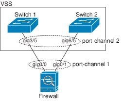
When the switch is part of a Virtual Switching System (VSS), then you can connect ASA interfaces within the same EtherChannel to separate switches in the VSS. The switch interfaces are members of the same EtherChannel port-channel interface, because the separate switches act like a single switch (see Figure 9-1).
Figure 9-1 Connecting to a VSS
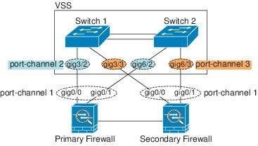
If you use the ASA in an Active/Standby failover deployment, then you need to create separate EtherChannels on the switches in the VSS, one for each ASA (see Figure 9-1). On each ASA, a single EtherChannel connects to both switches. Even if you could group all switch interfaces into a single EtherChannel connecting to both ASAs (in this case, the EtherChannel will not be established because of the separate ASA system IDs), a single EtherChannel would not be desirable because you do not want traffic sent to the standby ASA.
Figure 9-2 Active/Standby Failover and VSS
Link Aggregation Control Protocol
The Link Aggregation Control Protocol (LACP) aggregates interfaces by exchanging the Link Aggregation Control Protocol Data Units (LACPDUs) between two network devices.
You can configure each physical interface in an EtherChannel to be:
- Active—Sends and receives LACP updates. An active EtherChannel can establish connectivity with either an active or a passive EtherChannel. You should use the active mode unless you need to minimize the amount of LACP traffic.
- Passive—Receives LACP updates. A passive EtherChannel can only establish connectivity with an active EtherChannel.
- On—The EtherChannel is always on, and LACP is not used. An “on” EtherChannel can only establish a connection with another “on” EtherChannel.
LACP coordinates the automatic addition and deletion of links to the EtherChannel without user intervention. It also handles misconfigurations and checks that both ends of member interfaces are connected to the correct channel group. “On” mode cannot use standby interfaces in the channel group when an interface goes down, and the connectivity and configurations are not checked.
Load Balancing
The ASA distributes packets to the interfaces in the EtherChannel by hashing the source and destination IP address of the packet (this criteria is configurable; see the “Customizing the EtherChannel” section). The hash result is a 3-bit value (0 to 7).
The eight hash result values are distributed in a round robin fashion between the channel group interfaces, starting with the interface with the lowest ID (slot/port). For example, all packets with a hash result of 0 go to GigabitEthernet 0/0, packets with a hash result of 1 go to GigabitEthernet 0/1, packets with a hash result of 2 go to GigabitEthernet 0/2, and so on.
Because there are eight hash result values regardless of how many active interfaces are in the EtherChannel, packets might not be distributed evenly depending on the number of active interfaces.
Table 9-2 shows the load balancing amounts per interface for each number of active interfaces. The active interfaces in bold have even distribution.
|
|
|
|||||||
|---|---|---|---|---|---|---|---|---|
|
|
|
|
|
|
|
|
|
|
If an active interface goes down and is not replaced by a standby interface, then traffic is rebalanced between the remaining links. The failure is masked from both Spanning Tree at Layer 2 and the routing table at Layer 3, so the switchover is transparent to other network devices.
EtherChannel MAC Address
All interfaces that are part of the channel group share the same MAC address. This feature makes the EtherChannel transparent to network applications and users, because they only see the one logical connection; they have no knowledge of the individual links.
The port-channel interface uses the lowest numbered channel group interface MAC address as the port-channel MAC address. Alternatively you can manually configure a MAC address for the port-channel interface. In multiple context mode, you can automatically assign unique MAC addresses to interfaces, including an EtherChannel port interface. We recommend manually, or in multiple context mode, automatically configuring a unique MAC address in case the group channel interface membership changes. If you remove the interface that was providing the port-channel MAC address, then the port-channel MAC address changes to the next lowest numbered interface, thus causing traffic disruption.
Controlling Fragmentation with the Maximum Transmission Unit and TCP Maximum Segment Size
MTU Overview
The maximum transmission unit (MTU) specifies the maximum frame payload size (without Ethernet headers) that the ASA can transmit on a given Ethernet interface. If an outgoing IP packet is larger than the specified MTU, it is fragmented into 2 or more frames. Fragments are reassembled at the destination (and sometimes at intermediate hops), and fragmentation can cause performance degradation. Therefore, your IP packets should fit within the MTU size to avoid fragmentation.
Note![]() The ASA can receive frames larger than the configured MTU as long as there is room in memory. See the “Enabling Jumbo Frame Support (Supported Models)” section to increase memory for larger frames.
The ASA can receive frames larger than the configured MTU as long as there is room in memory. See the “Enabling Jumbo Frame Support (Supported Models)” section to increase memory for larger frames.
Default MTU
The default MTU on the ASA is 1500 bytes. This value does not include the 18 or more bytes for the Ethernet header, CRC, VLAN tagging, and so on.
Path MTU Discovery
The ASA supports Path MTU Discovery (as defined in RFC 1191), which lets all devices in a network path between two hosts coordinate the MTU so they can standardize on the lowest MTU in the path.
Setting the MTU and Jumbo Frames
See the “Configuring the MAC Address, MTU, and TCP MSS” section. For multiple context mode, set the MTU within each context.
See the “Enabling Jumbo Frame Support (Supported Models)” section. For multiple context mode, set the jumbo frame support in the system execution space.
- Matching MTUs on the traffic path—We recommend that you set the MTU on all ASA interfaces and other device interfaces along the traffic path to be the same. Matching MTUs prevents intermediate devices from fragmenting the packets.
- Accommodating jumbo frames—If your model supports jumbo frames, you can set the MTU up to 9216 bytes.
TCP Maximum Segment Size Overview
The TCP maximum segment size (TCP MSS) is the size of the TCP payload before any TCP headers are added. UDP packets are not affected. The client and the server exchange TCP MSS values during the three-way handshake when establishing the connection.
You can set the TCP MSS on the ASA. If either endpoint of a connection requests a TCP MSS that is larger than the value set on the ASA, the ASA overwrites the TCP MSS in the request packet with the ASA maximum. If the host or server does not request a TCP MSS, then the ASA assumes the RFC 793-default value of 536 bytes, but does not modify the packet. You can also configure the minimum TCP MSS; if a host or server requests a very small TCP MSS, the ASA can adjust the value up. By default, the minimum TCP MSS is not enabled.
For example, you configure the default MTU of 1500 bytes. A host requests an MSS of 1700. If the ASA maximum TCP MSS is 1380, then the ASA changes the MSS value in the TCP request packet to 1380. The server then sends 1380-byte packets.
Default TCP MSS
By default, the maximum TCP MSS on the ASA is 1380 bytes. This default accommodates VPN connections where the headers can add up to 120 bytes; this value fits within the default MTU of 1500 bytes.
Setting the TCP MSS for VPN and Non-VPN Traffic
See the “Configuring the MAC Address, MTU, and TCP MSS” section. For multiple context mode, set the TCP MSS within each context.
- Non-VPN traffic—If you do not use VPN and do not need extra space for headers, then you should disable the TCP MSS limit and accept the value established between connection endpoints. Because connection endpoints typically derive the TCP MSS from the MTU, non-VPN packets usually fit this TCP MSS.
- VPN traffic—Set the maximum TCP MSS to the MTU - 120. For example, if you use jumbo frames and set the MTU to a higher value, then you need to set the TCP MSS to accommodate the new MTU.
Examples
The following example enables jumbo frames, increases the MTU on all interfaces, and disables the TCP MSS for non-VPN traffic:
The following example enables jumbo frames, increases the MTU on all interfaces, and changes the TCP MSS for VPN traffic:
Licensing Requirements for ASA 5510 and Higher Interfaces
|
|
|
|---|---|
VLANs4: Base License—All interfaces Fast Ethernet. Security Plus License—Ethernet 0/0 and 0/1: Gigabit Ethernet; all others Fast Ethernet. Interfaces of all types5: |
|
VLANs 1 : Interfaces of all types 2 : |
|
VLANs 1 : Interfaces of all types 2 : |
|
VLANs 1 : Interfaces of all types 2 : |
|
VLANs 1 : Interfaces of all types 2 : |
|
VLANs 1 : Interfaces of all types 2 : |
|
VLANs 1 : Interfaces of all types 2 : |
|
VLANs 1 : Interfaces of all types 2 : |
|
VLANs 1 : Interfaces of all types 2 : |
|
VLANs 1 : Interfaces of all types 2 : |
|
VLANs 1 : Base and Security Plus License: 1024 Interface Speed for SSP-10 and SSP-20: Base License—1-Gigabit Ethernet for fiber interfaces 10 GE I/O License (Security Plus)—10-Gigabit Ethernet for fiber interfaces (SSP-40 and SSP-60 support 10-Gigabit Ethernet by default.) Interfaces of all types 2 : |
Guidelines and Limitations
This section includes the guidelines and limitations for this feature.
In multiple context mode, configure the physical interfaces in the system execution space according to the “Starting Interface Configuration (ASA 5510 and Higher)” section. Then, configure the logical interface parameters in the context execution space according to “Completing Interface Configuration (Routed Mode),” or Chapter12, “Completing Interface Configuration (Transparent Mode)”
- For transparent mode, you can configure up to eight bridge groups per context or for a single mode device.
- Each bridge group can include up to four interfaces.
- For multiple context, transparent mode, each context must use different interfaces; you cannot share an interface across contexts.
- When you use a redundant or EtherChannel interface as a failover link, it must be pre-configured on both units in the failover pair; you cannot configure it on the primary unit and expect it to replicate to the secondary unit because the failover link itself is required for replication .
- If you use a redundant or EtherChannel interface for the state link, no special configuration is required; the configuration can replicate from the primary unit as normal.
- You can monitor redundant or EtherChannel interfaces for failover using the monitor-interface command; be sure to reference the logical redundant interface name. When an active member interface fails over to a standby interface, this activity does not cause the redundant or EtherChannel interface to appear to be failed when being monitored for device-level failover. Only when all physical interfaces fail does the redundant or EtherChannel interface appear to be failed (for an EtherChannel interface, the number of member interfaces allowed to fail is configurable).
- If you use an EtherChannel interface for a failover or state link, then to prevent out-of-order packets, only one interface in the EtherChannel is used. If that interface fails, then the next interface in the EtherChannel is used. You cannot alter the EtherChannel configuration while it is in use as a failover link. To alter the configuration, you need to either shut down the EtherChannel while you make changes, or temporarily disable failover; either action prevents failover from occurring for the duration.
- Although you can configure the failover and failover state links on a port channel link, this port channel cannot be shared with other firewall traffic.
- When you use a redundant or EtherChannel interface as the cluster control link, it must be pre-configured on all units in the cluster; you cannot configure it on the primary unit and expect it to replicate to member units because the cluster control link itself is required for replication .
- To configure a spanned EtherChannel, see the “Configuring Spanned EtherChannels” section.
- To configure an individual cluster interface, see the “Configuring Individual Interfaces (Recommended for the Management Interface)” section.
Redundant Interface Guidelines
- You can configure up to 8 redundant interface pairs.
- All ASA configuration refers to the logical redundant interface instead of the member physical interfaces.
- You cannot use a redundant interface as part of an EtherChannel, nor can you use an EtherChannel as part of a redundant interface. You cannot use the same physical interfaces in a redundant interface and an EtherChannel interface. You can, however, configure both types on the ASA if they do not use the same physical interfaces.
- If you shut down the active interface, then the standby interface becomes active.
- Redundant interfaces do not support Management slot / port interfaces as members. You also cannot set a redundant interface comprised of non-Management interfaces as management-only.
- For failover guidelines, see the “Failover Guidelines” section.
- For clustering guidelines, see the “Clustering Guidelines” section.
- You can configure up to 48 EtherChannels.
- Each channel group can have eight active interfaces. Note that you can assign up to 16 interfaces to a channel group. While only eight interfaces can be active, the remaining interfaces can act as standby links in case of interface failure.
- All interfaces in the channel group must be the same type and speed. The first interface added to the channel group determines the correct type and speed.
- The device to which you connect the ASA EtherChannel must also support 802.3ad EtherChannels; for example, you can connect to the Catalyst 6500 switch.
- The ASA does not support LACPDUs that are VLAN-tagged. If you enable native VLAN tagging on the neighboring switch using the Cisco IOS vlan dot1Q tag native command, then the ASA will drop the tagged LACPDUs. Be sure to disable native VLAN tagging on the neighboring switch. In multiple context mode, these messages are not included in a packet capture, so you cannot diagnose the issue effectively.
- The ASA does not support connecting an EtherChannel to a switch stack. If the ASA EtherChannel is connected cross stack, and if the Master switch is powered down, then the EtherChannel connected to the remaining switch will not come up.
- All ASA configuration refers to the logical EtherChannel interface instead of the member physical interfaces.
- You cannot use a redundant interface as part of an EtherChannel, nor can you use an EtherChannel as part of a redundant interface. You cannot use the same physical interfaces in a redundant interface and an EtherChannel interface. You can, however, configure both types on the ASA if they do not use the same physical interfaces.
- You cannot use interfaces on the 4GE SSM, including the integrated 4GE SSM in slot 1 on the ASA 5550, as part of an EtherChannel.
- For failover guidelines, see the “Failover Guidelines” section.
- For clustering guidelines, see the “Clustering Guidelines” section.
Default Settings
This section lists default settings for interfaces if you do not have a factory default configuration. For information about the factory default configurations, see the “Factory Default Configurations” section.
The default state of an interface depends on the type and the context mode.
In multiple context mode, all allocated interfaces are enabled by default, no matter what the state of the interface is in the system execution space. However, for traffic to pass through the interface, the interface also has to be enabled in the system execution space. If you shut down an interface in the system execution space, then that interface is down in all contexts that share it.
In single mode or in the system execution space, interfaces have the following default states:
- Physical interfaces—Disabled.
- Redundant Interfaces—Enabled. However, for traffic to pass through the redundant interface, the member physical interfaces must also be enabled.
- Subinterfaces—Enabled. However, for traffic to pass through the subinterface, the physical interface must also be enabled.
- EtherChannel port-channel interfaces—Enabled. However, for traffic to pass through the EtherChannel, the channel group physical interfaces must also be enabled.
- By default, the speed and duplex for copper (RJ-45) interfaces are set to auto-negotiate.
- The fiber interface for the ASA 5550 (slot 1) and the 4GE SSM has a fixed speed and does not support duplex, but you can set the interface to negotiate link parameters (the default) or not to negotiate.
- For fiber interfaces for the ASA 5580 and 5585-X, the speed is set for automatic link negotiation.
The ASA 5550 (slot 1) and the 4GE SSM for the ASA 5510 and higher ASA include two connector types: copper RJ-45 and fiber SFP. RJ-45 is the default. You can configure the ASA to use the fiber SFP connectors.
By default, the physical interface uses the burned-in MAC address, and all subinterfaces of a physical interface use the same burned-in MAC address.
Starting Interface Configuration (ASA 5510 and Higher)
This section includes the following topics:
- Task Flow for Starting Interface Configuration
- Converting In-Use Interfaces to a Redundant or EtherChannel Interface
- Enabling the Physical Interface and Configuring Ethernet Parameters
- Configuring a Redundant Interface
- Configuring an EtherChannel
- Configuring VLAN Subinterfaces and 802.1Q Trunking
- Enabling Jumbo Frame Support (Supported Models)
Task Flow for Starting Interface Configuration
Note![]() If you have an existing configuration, and want to convert interfaces that are in use to a redundant or EtherChannel interface, perform your configuration offline to minimize disruption. See the “Converting In-Use Interfaces to a Redundant or EtherChannel Interface” section.
If you have an existing configuration, and want to convert interfaces that are in use to a redundant or EtherChannel interface, perform your configuration offline to minimize disruption. See the “Converting In-Use Interfaces to a Redundant or EtherChannel Interface” section.
To start configuring interfaces, perform the following steps:
Step 1![]() (Multiple context mode) Complete all tasks in this section in the system execution space. To change from the context to the system execution space, enter the changeto system
(Multiple context mode) Complete all tasks in this section in the system execution space. To change from the context to the system execution space, enter the changeto system![]() command.
command.
Step 2![]() Enable the physical interface, and optionally change Ethernet parameters. See the “Enabling the Physical Interface and Configuring Ethernet Parameters” section.
Enable the physical interface, and optionally change Ethernet parameters. See the “Enabling the Physical Interface and Configuring Ethernet Parameters” section.
Physical interfaces are disabled by default.
Step 3![]() (Optional) Configure redundant interface pairs. See the “Configuring a Redundant Interface” section.
(Optional) Configure redundant interface pairs. See the “Configuring a Redundant Interface” section.
A logical redundant interface pairs an active and a standby physical interface. When the active interface fails, the standby interface becomes active and starts passing traffic.
Step 4![]() (Optional) Configure an EtherChannel. See the “Configuring an EtherChannel” section.
(Optional) Configure an EtherChannel. See the “Configuring an EtherChannel” section.
An EtherChannel groups multiple Ethernet interfaces into a single logical interface.
Note You cannot use interfaces on the 4GE SSM, including the integrated 4GE SSM in slot 1 on the ASA 5550, as part of an EtherChannel.
Step 5![]() (Optional) Configure VLAN subinterfaces. See the “Configuring VLAN Subinterfaces and 802.1Q Trunking” section.
(Optional) Configure VLAN subinterfaces. See the “Configuring VLAN Subinterfaces and 802.1Q Trunking” section.
Step 6![]() (Optional) Enable jumbo frame support on the ASA 5580 and 5585-X according to the “Enabling Jumbo Frame Support (Supported Models)” section.
(Optional) Enable jumbo frame support on the ASA 5580 and 5585-X according to the “Enabling Jumbo Frame Support (Supported Models)” section.
Step 7![]() (Multiple context mode only) To complete the configuration of interfaces in the system execution space, perform the following tasks that are documented in Chapter 6, “Configuring Multiple Context Mode”:
(Multiple context mode only) To complete the configuration of interfaces in the system execution space, perform the following tasks that are documented in Chapter 6, “Configuring Multiple Context Mode”:
- To assign interfaces to contexts, see the “Configuring a Security Context” section.
- (Optional) To automatically assign unique MAC addresses to context interfaces, see the “Automatically Assigning MAC Addresses to Context Interfaces” section.
The MAC address is used to classify packets within a context. If you share an interface, but do not have unique MAC addresses for the interface in each context, then the destination IP address is used to classify packets. Alternatively, you can manually assign MAC addresses within the context according to the “Configuring the MAC Address, MTU, and TCP MSS” section.
Step 8![]() Complete the interface configuration according to “Completing Interface Configuration (Routed Mode),” or Chapter12, “Completing Interface Configuration (Transparent Mode)”
Complete the interface configuration according to “Completing Interface Configuration (Routed Mode),” or Chapter12, “Completing Interface Configuration (Transparent Mode)”
Converting In-Use Interfaces to a Redundant or EtherChannel Interface
If you have an existing configuration and want to take advantage of the redundant or EtherChannel interface feature for interfaces that are currently in use, you will have some amount of downtime when you convert to the logical interfaces.
This section provides an overview of how to convert your existing interfaces to a redundant or EtherChannel interface with minimal downtime. See the “Configuring a Redundant Interface” section and the “Configuring an EtherChannel” section fore more information.
Detailed Steps (Single Mode)
We recommend that you update your configuration offline as a text file, and reimport the whole configuration for the following reasons:
- Because you cannot add a named interface as a member of a redundant or EtherChannel interface, you must remove the name from the interface. When you remove the name from the interface, any command that referred to that name is deleted. Because commands that refer to interface names are widespread throughout the configuration and affect multiple features, removing a name from an in-use interface at the CLI or in ASDM would cause significant damage to your configuration, not to mention significant downtime while you reconfigure all your features around a new interface name.
- Changing your configuration offline lets you use the same interface names for your new logical interfaces, so you do not need to touch the feature configurations that refer to interface names. You only need to change the interface configuration.
- Clearing the running configuration and immediately applying a new configuration will minimize the downtime of your interfaces. You will not be waiting to configure the interfaces in real time.
Step 1![]() Connect to the ASA; if you are using failover, connect to the active ASA.
Connect to the ASA; if you are using failover, connect to the active ASA.
Step 2![]() If you are using failover, disable failover by entering the no failover command.
If you are using failover, disable failover by entering the no failover command.
Step 3![]() Copy the running configuration by entering the more system
Copy the running configuration by entering the more system![]() :running-config command and copying the display output to a text editor.
:running-config command and copying the display output to a text editor.
Be sure to save an extra copy of the old configuration in case you make an error when you edit it.
Step 4![]() For each in-use interface that you want to add to a redundant or EtherChannel interface, cut and paste all commands under the interface command to the end of the interface configuration section for use in creating your new logical interfaces. The only exceptions are the following commands, which should stay with the physical interface configuration:
For each in-use interface that you want to add to a redundant or EtherChannel interface, cut and paste all commands under the interface command to the end of the interface configuration section for use in creating your new logical interfaces. The only exceptions are the following commands, which should stay with the physical interface configuration:
Note You can only add physical interfaces to an EtherChannel or redundant interface; you cannot have VLANs configured for the physical interfaces.
Be sure to match the above values for all interfaces in a given EtherChannel or redundant interface. Note that the duplex setting for an EtherChannel interface must be Full or Auto.
For example, you have the following interface configuration. The bolded commands are the ones we want to use with three new EtherChannel interfaces, and that you should cut and paste to the end of the interface section.
Step 5![]() Above each pasted command section, create your new logical interfaces by entering one of the following commands:
Above each pasted command section, create your new logical interfaces by entering one of the following commands:
Step 6![]() Assign the physical interfaces to the new logical interfaces:
Assign the physical interfaces to the new logical interfaces:
Where the physical interfaces are any two interfaces of the same type (either formerly in use or unused). You cannot assign a Management interface to a redundant interface.
For example, to take advantage of existing cabling, you would continue to use the formerly in-use interfaces in their old roles as part of the inside and outside redundant interfaces:
For example, to take advantage of existing cabling, you would continue to use the formerly in-use interfaces in their old roles as part of the inside and outside EtherChannel interfaces:
Step 7![]() Enable each formerly unused interface that is now part of a logical interface by adding no in front of the shutdown command.
Enable each formerly unused interface that is now part of a logical interface by adding no in front of the shutdown command.
For example, your final EtherChannel configuration is:
Note Other optional EtherChannel parameters can be configured after you import the new configuration. See the “Configuring an EtherChannel” section.
Step 8![]() At the ASA CLI prompt, perform the following steps depending on your connection (console or remote).
At the ASA CLI prompt, perform the following steps depending on your connection (console or remote).
a.![]() Copy the entire new configuration to the clipboard, including the altered interface section.
Copy the entire new configuration to the clipboard, including the altered interface section.
b.![]() Clear the running configuration by entering:
Clear the running configuration by entering:
Traffic through the ASA stops at this point.
c.![]() Paste in the new configuration at the prompt.
Paste in the new configuration at the prompt.
Traffic through the ASA resumes.
a.![]() Save the new configuration to a TFTP or FTP server, so you can copy it to the startup configuration on the ASA. For example, you can run a TFTP or FTP server on your PC.
Save the new configuration to a TFTP or FTP server, so you can copy it to the startup configuration on the ASA. For example, you can run a TFTP or FTP server on your PC.
b.![]() Clear the startup configuration by entering:
Clear the startup configuration by entering:
c.![]() Copy the new configuration to the startup configuration by entering:
Copy the new configuration to the startup configuration by entering:
See the “Copying a File to the ASA” section
d.![]() Reload the ASA using the reload command. Do not save the running configuration.
Reload the ASA using the reload command. Do not save the running configuration.
Step 9![]() Reenable failover by entering the failover command.
Reenable failover by entering the failover command.
Detailed Steps (Multiple Mode)
We recommend that you update your system and context configurations offline as text files, and reimport them for the following reasons:
- Because you cannot add an allocated interface as a member of a redundant or EtherChannel interface, you must deallocate the interface from any contexts. When you deallocate the interface, any context command that referred to that interface is deleted. Because commands that refer to interfaces are widespread throughout the configuration and affect multiple features, removing an allocation from an in-use interface at the CLI or in ASDM would cause significant damage to your configuration, not to mention significant downtime while you reconfigure all your features around a new interface.
- Changing your configuration offline lets you use the same interface names for your new logical interfaces, so you do not need to touch the feature configurations that refer to interface names. You only need to change the interface configuration.
- Clearing the running system configuration and immediately applying a new configuration will minimize the downtime of your interfaces. You will not be waiting to configure the interfaces in real time.
Step 1![]() Connect to the ASA, and change to the system; if you are using failover, connect to the active ASA.
Connect to the ASA, and change to the system; if you are using failover, connect to the active ASA.
Step 2![]() If you are using failover, disable failover by entering the no failover command.
If you are using failover, disable failover by entering the no failover command.
Step 3![]() In the system, copy the running configuration by entering the more system
In the system, copy the running configuration by entering the more system![]() :running-config command and copying the display output to a text editor.
:running-config command and copying the display output to a text editor.
Be sure to save an extra copy of the old configuration in case you make an error when you edit it.
For example, you have the following interface configuration and allocation in the system configuration, with shared interfaces between two contexts.
Step 4![]() Get copies of all context configurations that will use the new EtherChannel or redundant interface. See the “Backing Up Configurations or Other Files” section.
Get copies of all context configurations that will use the new EtherChannel or redundant interface. See the “Backing Up Configurations or Other Files” section.
For example, you download the following context configurations (interface configuration shown):
Step 5![]() In the system configuration, create the new logical interfaces according to the “Configuring a Redundant Interface” section or the “Configuring an EtherChannel” section. Be sure to enter the no shutdown command on any additional physical interfaces you want to use as part of the logical interface.
In the system configuration, create the new logical interfaces according to the “Configuring a Redundant Interface” section or the “Configuring an EtherChannel” section. Be sure to enter the no shutdown command on any additional physical interfaces you want to use as part of the logical interface.
Note You can only add physical interfaces to an EtherChannel or redundant interface; you cannot have VLANs configured for the physical interfaces.
Be sure to match physical interface parameters such as speed and duplex for all interfaces in a given EtherChannel or redundant interface. Note that the duplex setting for an EtherChannel interface must be Full or Auto.
For example, the new configuration is:
Step 6![]() Change the interface allocation per context to use the new EtherChannel or redundant interfaces. See the “Configuring a Security Context” section.
Change the interface allocation per context to use the new EtherChannel or redundant interfaces. See the “Configuring a Security Context” section.
For example, to take advantage of existing cabling, you would continue to use the formerly in-use interfaces in their old roles as part of the inside and outside redundant interfaces:
Note You might want to take this opportunity to assign mapped names to interfaces if you have not done so already. For example, the configuration for customerA does not need to be altered at all; it just needs to be reapplied on the ASA. The customerB configuration, however, needs to have all of the interface IDs changed; if you assign mapped names for customerB, you still have to change the interface IDs in the context configuration, but mapped names might help future interface changes.
Step 7![]() For contexts that do not use mapped names, change the context configuration to use the new EtherChannel or redundant interface ID. (Contexts that use mapped interface names do not require any alteration.)
For contexts that do not use mapped names, change the context configuration to use the new EtherChannel or redundant interface ID. (Contexts that use mapped interface names do not require any alteration.)
Step 8![]() Copy the new context configuration files over the old ones. For example, if your contexts are on an FTP server, copy over the existing files (making backups as desired) using FTP. If your contexts are in flash memory, you can use the copy command and run a TFTP or FTP server on your PC, or use secure copy. See the “Copying a File to the ASA” section. This change only affects the startup configuration; the running configuration is still using the old context configuration.
Copy the new context configuration files over the old ones. For example, if your contexts are on an FTP server, copy over the existing files (making backups as desired) using FTP. If your contexts are in flash memory, you can use the copy command and run a TFTP or FTP server on your PC, or use secure copy. See the “Copying a File to the ASA” section. This change only affects the startup configuration; the running configuration is still using the old context configuration.
Step 9![]() At the ASA system CLI prompt, perform the following steps depending on your connection (console or remote).
At the ASA system CLI prompt, perform the following steps depending on your connection (console or remote).
a.![]() Copy the entire new system configuration to the clipboard, including the altered interface section.
Copy the entire new system configuration to the clipboard, including the altered interface section.
b.![]() Clear the running configuration (both system and contexts) by entering:
Clear the running configuration (both system and contexts) by entering:
Traffic through the ASA stops at this point.
c.![]() Paste in the new system configuration at the prompt.
Paste in the new system configuration at the prompt.
All of the new context configurations now reload. When they are finished reloading, traffic through the ASA resumes.
a.![]() Save the new system configuration to a TFTP or FTP server, so you can copy it to the startup configuration on the ASA. For example, you can run a TFTP or FTP server on your PC.
Save the new system configuration to a TFTP or FTP server, so you can copy it to the startup configuration on the ASA. For example, you can run a TFTP or FTP server on your PC.
b.![]() Clear the startup configuration by entering:
Clear the startup configuration by entering:
c.![]() Copy the new system configuration to the startup configuration by entering:
Copy the new system configuration to the startup configuration by entering:
See the “Copying a File to the ASA” section
d.![]() Reload the ASA using the reload command. Do not save the running configuration.
Reload the ASA using the reload command. Do not save the running configuration.
Step 10![]() Reenable failover by entering the failover command.
Reenable failover by entering the failover command.
Enabling the Physical Interface and Configuring Ethernet Parameters
Prerequisites
For multiple context mode, complete this procedure in the system execution space. To change from the context to the system execution space, enter the changeto system command.
Detailed Steps
What to Do Next
- Configure redundant interface pairs. See the “Configuring a Redundant Interface” section.
- Configure an EtherChannel. See the “Configuring an EtherChannel” section.
- Configure VLAN subinterfaces. See the “Configuring VLAN Subinterfaces and 802.1Q Trunking” section.
- For multiple context mode, assign interfaces to contexts and automatically assign unique MAC addresses to context interfaces. See the “Configuring Multiple Contexts” section.
- For single context mode, complete the interface configuration. See “Completing Interface Configuration (Routed Mode),” or Chapter12, “Completing Interface Configuration (Transparent Mode)”
Configuring a Redundant Interface
A logical redundant interface consists of a pair of physical interfaces: an active and a standby interface. When the active interface fails, the standby interface becomes active and starts passing traffic. You can configure a redundant interface to increase the ASA reliability. This feature is separate from device-level failover, but you can configure redundant interfaces as well as failover if desired.
This section describes how to configure redundant interfaces and includes the following topics:
Configuring a Redundant Interface
This section describes how to create a redundant interface. By default, redundant interfaces are enabled.
Guidelines and Limitations
- You can configure up to 8 redundant interface pairs.
- Redundant interface delay values are configurable, but by default the ASA inherits the default delay values based on the physical type of its member interfaces.
- See also the “Redundant Interface Guidelines” section.
Prerequisites
- Both member interfaces must be of the same physical type. For example, both must be Ethernet.
- You cannot add a physical interface to the redundant interface if you configured a name for it. You must first remove the name using the no nameif command.
- For multiple context mode, complete this procedure in the system execution space. To change from the context to the system execution space, enter the changeto system command.

Detailed Steps
|
|
|
|
|---|---|---|
|
|
Adds the logical redundant interface, where the number argument is an integer between 1 and 8. Note You need to add at least one member interface to the redundant interface before you can configure logical parameters for it such as a name. |
|
member-interface physical_interface |
Adds the first member interface to the redundant interface. See the “Enabling the Physical Interface and Configuring Ethernet Parameters” section for a description of the physical interface ID. Redundant interfaces do not support Management slot / port interfaces as members. After you add the interface, any configuration for it (such as an IP address) is removed. |
|
member-interface physical_interface |
Adds the second member interface to the redundant interface. Make sure the second interface is the same physical type as the first interface. To remove a member interface, enter the no member-interface physical_interface command. You cannot remove both member interfaces from the redundant interface; the redundant interface requires at least one member interface. |
Examples
The following example creates two redundant interfaces:
What to Do Next
- Configure VLAN subinterfaces. See the “Configuring VLAN Subinterfaces and 802.1Q Trunking” section.
- For multiple context mode, assign interfaces to contexts and automatically assign unique MAC addresses to context interfaces. See the “Configuring Multiple Contexts” section.
- For single context mode, complete the interface configuration. See the “Completing Interface Configuration (Routed Mode),” or Chapter12, “Completing Interface Configuration (Transparent Mode)”
Changing the Active Interface
By default, the active interface is the first interface listed in the configuration, if it is available. To view which interface is active, enter the following command:
To change the active interface, enter the following command:
where the redundant number argument is the redundant interface ID, such as redundant1 .
The physical_interface is the member interface ID that you want to be active.
Configuring an EtherChannel
This section describes how to create an EtherChannel port-channel interface, assign interfaces to the EtherChannel, and customize the EtherChannel.
Adding Interfaces to the EtherChannel
This section describes how to create an EtherChannel port-channel interface and assign interfaces to the EtherChannel. By default, port-channel interfaces are enabled.
Guidelines and Limitations
- You can configure up to 48 EtherChannels.
- Each channel group can have eight active interfaces. Note that you can assign up to 16 interfaces to a channel group. While only eight interfaces can be active, the remaining interfaces can act as standby links in case of interface failure.
- You cannot use interfaces on the 4GE SSM, including the integrated 4GE SSM in slot 1 on the ASA 5550, as part of an EtherChannel.
- To configure a spanned EtherChannel for clustering, see the “Configuring Spanned EtherChannels” section instead of this procedure.
- See also the “EtherChannel Guidelines” section.
Prerequisites
- All interfaces in the channel group must be the same type, speed, and duplex. Half duplex is not supported.
- You cannot add a physical interface to the channel group if you configured a name for it. You must first remove the name using the no nameif command.
- For multiple context mode, complete this procedure in the system execution space. To change from the context to the system execution space, enter the changeto system command.
Detailed Steps
|
|
|
|
|---|---|---|
|
|
Specifies the interface you want to add to the channel group, where the physical_interface ID includes the type, slot, and port number as type [ slot / ] port . This first interface in the channel group determines the type and speed for all other interfaces in the group. In transparent mode, if you create a channel group with multiple Management interfaces, then you can use this EtherChannel as the management-only interface. |
|
channel-group channel_id mode { active | passive | on } |
Assigns this physical interface to an EtherChannel with the channel_id between 1 and 48. If the port-channel interface for this channel ID does not yet exist in the configuration, one will be added: interface port-channel channel_id We recommend using active mode. For information about active, passive, and on modes, see the “Link Aggregation Control Protocol” section. |
|
|
|
Sets the priority for a physical interface in the channel group between 1 and 65535. The default is 32768. The higher the number, the lower the priority. The ASA uses this setting to decide which interfaces are active and which are standby if you assign more interfaces than can be used. If the port priority setting is the same for all interfaces, then the priority is determined by the interface ID (slot/port). The lowest interface ID is the highest priority. For example, GigabitEthernet 0/0 is a higher priority than GigabitEthernet 0/1. If you want to prioritize an interface to be active even though it has a higher interface ID, then set this command to have a lower value. For example, to make GigabitEthernet 1/3 active before GigabitEthernet 0/7, then make the lacp port-priority value be 12345 on the 1/3 interface vs. the default 32768 on the 0/7 interface. If the device at the other end of the EtherChannel has conflicting port priorities, the system priority is used to determine which port priorities to use. See the lacp system-priority command in the “Customizing the EtherChannel” section. |
|
Repeat steps 1 through 3 for each interface you want to add to the channel group. |
Each interface in the channel group must be the same type and speed. Half duplex is not supported. If you add an interface that does not match, it will be placed in a suspended state. |
What to Do Next
- Customize the EtherChannel interface. See the “Customizing the EtherChannel” section.
- Configure VLAN subinterfaces. See the “Configuring VLAN Subinterfaces and 802.1Q Trunking” section.
- For multiple context mode, assign interfaces to contexts and automatically assign unique MAC addresses to context interfaces. See the “Configuring Multiple Contexts” section.
- For single context mode, complete the interface configuration. See the “Completing Interface Configuration (Routed Mode),” or Chapter12, “Completing Interface Configuration (Transparent Mode)”
Customizing the EtherChannel
This section describes how to set the maximum number of interfaces in the EtherChannel, the minimum number of operating interfaces for the EtherChannel to be active, the load balancing algorithm, and other optional parameters.
Detailed Steps
|
|
|
|
|---|---|---|
interface port-channel channel_id |
Specifies the port-channel interface. This interface was created automatically when you added an interface to the channel group. If you have not yet added an interface, then this command creates the port-channel interface. Note You need to add at least one member interface to the port-channel interface before you can configure logical parameters for it such as a name. |
|
|
|
Specifies the maximum number of active interfaces allowed in the channel group, between 1 and 8. The default is 8. |
|
port-channel min-bundle number |
Specifies the minimum number of active interfaces required for the port-channel interface to become active, between 1 and 8. The default is 1. If the active interfaces in the channel group falls below this value, then the port-channel interface goes down, and could trigger a device-level failover. |
|
port-channel load-balance { dst-ip | dst-ip-port | dst-mac | dst-port | src-dst-ip | src-dst-ip-port | src-dst-mac | src-dst-port | src-ip | src-ip-port | src-mac | src-port | vlan-dst-ip | vlan-dst-ip-port | vlan-only | vlan-src-dst-ip | vlan-src-dst-ip-port | vlan-src-ip | vlan-src-ip-port } |
Configures the load-balancing algorithm. By default, the ASA balances the packet load on interfaces according to the source and destination IP address ( src-dst-ip ) of the packet. If you want to change the properties on which the packet is categorized, use this command. For example, if your traffic is biased heavily towards the same source and destination IP addresses, then the traffic assignment to interfaces in the EtherChannel will be unbalanced. Changing to a different algorithm can result in more evenly distributed traffic. For more information about load balancing, see the “Load Balancing” section. |
|
|
|
Sets the LACP system priority, from 1 to 65535. The default is 32768. The higher the number, the lower the priority. This command is global for the ASA. If the device at the other end of the EtherChannel has conflicting port priorities, the system priority is used to determine which port priorities to use. For interface priorities within an EtherChannel, see the lacp port-priority command in the “Adding Interfaces to the EtherChannel” section. |
|
| You can set the Ethernet properties for the port-channel interface to override the properties set on the individual interfaces. |
This method provides a shortcut to set these parameters because these parameters must match for all interfaces in the channel group. See the “Enabling the Physical Interface and Configuring Ethernet Parameters” section for Ethernet commands. |
What to Do Next
- Configure VLAN subinterfaces. See the “Configuring VLAN Subinterfaces and 802.1Q Trunking” section.
- For multiple context mode, assign interfaces to contexts and automatically assign unique MAC addresses to context interfaces. See the “Configuring Multiple Contexts” section.
- For single context mode, complete the interface configuration. See the “Completing Interface Configuration (Routed Mode),” or Chapter12, “Completing Interface Configuration (Transparent Mode)”
Configuring VLAN Subinterfaces and 802.1Q Trunking
Subinterfaces let you divide a physical, redundant, or EtherChannel interface into multiple logical interfaces that are tagged with different VLAN IDs. An interface with one or more VLAN subinterfaces is automatically configured as an 802.1Q trunk. Because VLANs allow you to keep traffic separate on a given physical interface, you can increase the number of interfaces available to your network without adding additional physical interfaces or ASAs. This feature is particularly useful in multiple context mode so that you can assign unique interfaces to each context.
Guidelines and Limitations
- Maximum subinterfaces—To determine how many VLAN subinterfaces are allowed for your platform, see the “Licensing Requirements for ASA 5510 and Higher Interfaces” section.
- Preventing untagged packets on the physical interface—If you use subinterfaces, you typically do not also want the physical interface to pass traffic, because the physical interface passes untagged packets. This property is also true for the active physical interface in a redundant interface pair. Because the physical or redundant interface must be enabled for the subinterface to pass traffic, ensure that the physical or redundant interface does not pass traffic by leaving out the nameif command. If you want to let the physical or redundant interface pass untagged packets, you can configure the nameif command as usual. See “Completing Interface Configuration (Routed Mode),” or “Completing Interface Configuration (Transparent Mode),” for more information about completing the interface configuration.
- (ASA 5512-X through ASA 5555-X) You cannot configure subinterfaces on the Management 0/0 interface.
Prerequisites
For multiple context mode, complete this procedure in the system execution space. To change from the context to the system execution space, enter the changeto system command.
Detailed Steps
|
|
|
|
|---|---|---|
interface { physical_interface | redundant number | port-channel number } . subinterface |
Specifies the new subinterface. See the “Enabling the Physical Interface and Configuring Ethernet Parameters” section for a description of the physical interface ID. The redundant number argument is the redundant interface ID, such as redundant 1 . The port-channel number argument is the EtherChannel interface ID, such as port-channel 1 . |
|
|
|
Specifies the VLAN for the subinterface. The vlan_id is an integer between 1 and 4094. Some VLAN IDs might be reserved on connected switches, so check the switch documentation for more information. You can only assign a single VLAN to a subinterface, and you cannot assign the same VLAN to multiple subinterfaces. You cannot assign a VLAN to the physical interface. Each subinterface must have a VLAN ID before it can pass traffic. To change a VLAN ID, you do not need to remove the old VLAN ID with the no option; you can enter the vlan command with a different VLAN ID, and the ASA changes the old ID. |
What to Do Next
(Optional) Enable jumbo frame support according to the “Enabling Jumbo Frame Support (Supported Models)” section.
Enabling Jumbo Frame Support (Supported Models)
A jumbo frame is an Ethernet packet larger than the standard maximum of 1518 bytes (including Layer 2 header and FCS), up to 9216 bytes. You can enable support for jumbo frames for all interfaces by increasing the amount of memory to process Ethernet frames. Assigning more memory for jumbo frames might limit the maximum use of other features, such as ACLs. See the “Controlling Fragmentation with the Maximum Transmission Unit and TCP Maximum Segment Size” section for more information.
Prerequisites
- In multiple context mode, set this option in the system execution space.
- Changes in this setting require you to reload the ASA.
- Be sure to set the MTU for each interface that needs to transmit jumbo frames to a higher value than the default 1500; for example, set the value to 9000 using the mtu command. See the “Configuring the MAC Address, MTU, and TCP MSS” section. In multiple context mode, set the MTU within each context.
- Be sure to adjust the TCP MSS, either to disable it for non-VPN traffic ( sysopt connection tcpmss 0 ), or to increase it in accord with the MTU according to the “Configuring the MAC Address, MTU, and TCP MSS” section.
Detailed Steps
|
|
|
|---|---|
|
|
Enables jumbo frame support. To disable jumbo frames, use the no form of this command. |
Examples
The following example enables jumbo frame reservation, saves the configuration, and reloads the ASA:
Monitoring Interfaces
To monitor interfaces, enter one of the following commands:
Configuration Examples for ASA 5510 and Higher Interfaces
This section includes the following topics:
- Physical Interface Parameters Example
- Subinterface Parameters Example
- Multiple Context Mode Example
- EtherChannel Example
Physical Interface Parameters Example
The following example configures parameters for the physical interface in single mode:
Subinterface Parameters Example
The following example configures parameters for a subinterface in single mode:
Multiple Context Mode Example
The following example configures interface parameters in multiple context mode for the system configuration, and allocates the gigabitethernet 0/1.1 subinterface to contextA:
EtherChannel Example
The following example configures three interfaces as part of an EtherChannel. It also sets the system priority to be a higher priority, and GigabitEthernet 0/2 to be a higher priority than the other interfaces in case more than eight interfaces are assigned to the EtherChannel.
Where to Go Next
a.![]() Assign interfaces to contexts and automatically assign unique MAC addresses to context interfaces. See Chapter6, “Configuring Multiple Context Mode”
Assign interfaces to contexts and automatically assign unique MAC addresses to context interfaces. See Chapter6, “Configuring Multiple Context Mode”
b.![]() Complete the interface configuration according to “Completing Interface Configuration (Routed Mode),” or Chapter12, “Completing Interface Configuration (Transparent Mode)”
Complete the interface configuration according to “Completing Interface Configuration (Routed Mode),” or Chapter12, “Completing Interface Configuration (Transparent Mode)”
- For single context mode, complete the interface configuration according to “Completing Interface Configuration (Routed Mode),” or Chapter12, “Completing Interface Configuration (Transparent Mode)”
Feature History for ASA 5510 and Higher Interfaces
Table 9-3 lists the release history for this feature.
 Feedback