Installing the Cisco XR 12406 Router
This chapter describes how to install the Cisco XR 12406 router. It includes the following sections:
•![]() Supplemental Bonding and Grounding Connections
Supplemental Bonding and Grounding Connections
•![]() Connecting RP and Line Card Cables
Connecting RP and Line Card Cables
•![]() Connecting to the Console and Auxiliary Ports
Connecting to the Console and Auxiliary Ports
•![]() Connecting to an AC Power Source
Connecting to an AC Power Source
•![]() Connecting to a DC Power Source
Connecting to a DC Power Source
•![]() Powering On the Router—First Time
Powering On the Router—First Time
Required Tools
You need the following items to install the Cisco XR 12406 router:
•![]() Number 2 Phillips screwdriver
Number 2 Phillips screwdriver
•![]() Small flat-bladed screwdriver
Small flat-bladed screwdriver
•![]() Tape measure (optional)
Tape measure (optional)
•![]() Level (optional)
Level (optional)
Installing a Router
This section provides the procedures for installing the Cisco XR 12406 router and contains the following sections:
•![]() Installing the Rack-Mounting Brackets—Optional
Installing the Rack-Mounting Brackets—Optional
•![]() Installing the Chassis in a Rack
Installing the Chassis in a Rack
•![]() Installing Center-Mounting Brackets (optional)
Installing Center-Mounting Brackets (optional)
•![]() Installing the Chassis on a Tabletop or Flat Surface
Installing the Chassis on a Tabletop or Flat Surface
Your installation site should already be prepared before you begin installing the router. For complete information about site preparation see Chapter 2, "Preparing for Installation".
Make sure that you have considered the following before you install the router:
•![]() The exhaust vents on the blower module mounted at the rear of the chassis are not blocked.
The exhaust vents on the blower module mounted at the rear of the chassis are not blocked.
•![]() The air filter is mounted on the right side as you face the router; air flow to the blower module is not blocked.
The air filter is mounted on the right side as you face the router; air flow to the blower module is not blocked.
•![]() There is 24 inches (61 cm) of clearance at the rear of the chassis so you can read the blower module LEDs and perform maintenance on the module.
There is 24 inches (61 cm) of clearance at the rear of the chassis so you can read the blower module LEDs and perform maintenance on the module.
•![]() There is 24 inches (61 cm) of clearance in front of the router chassis to enable working with line cards and power supplies, and attaching Network Interface Cable (NICs) or other components.
There is 24 inches (61 cm) of clearance in front of the router chassis to enable working with line cards and power supplies, and attaching Network Interface Cable (NICs) or other components.
•![]() Location is temperature controlled, air conditioned, and dust free.
Location is temperature controlled, air conditioned, and dust free.
•![]() Power cables and power supplies have been checked for compatibility with your power service.
Power cables and power supplies have been checked for compatibility with your power service.
•![]() Labels on the equipment have been checked to ensure that the power service at your site is suitable for the router.
Labels on the equipment have been checked to ensure that the power service at your site is suitable for the router.
•![]() AC power source receptacles are easy to reach.
AC power source receptacles are easy to reach.
Installing the Rack-Mounting Brackets—Optional
The rack-mounting brackets temporarily bear the weight of the router while it is being positioned in the rack.
While the use of the rack-mounting is optional, installing them makes it much easier to mount the router in a rack, and also ensures that the router is level. The rack-mounting brackets can be left in place following the router installation.

Warning ![]() Two or more people should install the router to minimize the risk of personal injury and damage to the equipment.
Two or more people should install the router to minimize the risk of personal injury and damage to the equipment.
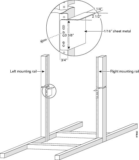
Refer to Figure 3-1 and use the following procedure to install the rack-mounting brackets.
Step 1 ![]() Measure and mark the hole at the same height on both the left and right rack rails.
Measure and mark the hole at the same height on both the left and right rack rails.
Step 2 ![]() Mount the right mounting bracket:
Mount the right mounting bracket:
a. ![]() Hold the right rack-mount bracket against the right rack rail and align the bottom screw hole in the bracket with the marked screw hole on the rail.
Hold the right rack-mount bracket against the right rack rail and align the bottom screw hole in the bracket with the marked screw hole on the rail.
b. ![]() Insert a screw through the bottom hole in the bracket and finger tighten the screw.
Insert a screw through the bottom hole in the bracket and finger tighten the screw.
c. ![]() Insert and finger tighten a second screw in the top hole in the bracket.
Insert and finger tighten a second screw in the top hole in the bracket.
Step 3 ![]() Follow Step 2a through Step 2c to mount the left rack-mount bracket.
Follow Step 2a through Step 2c to mount the left rack-mount bracket.
Step 4 ![]() Use a level to verify that the tops of the two brackets are level, or use a measuring tape to verify that both brackets are the same distance from the tops of both rack rails.
Use a level to verify that the tops of the two brackets are level, or use a measuring tape to verify that both brackets are the same distance from the tops of both rack rails.
Step 5 ![]() Use a screwdriver to tighten all the screws.
Use a screwdriver to tighten all the screws.
Figure 3-1 Installing the Optional Rack-Mount Brackets
Installing Center-Mounting Brackets (optional)
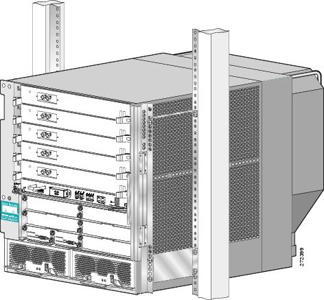
To install the Cisco XR 12406 router in the center-mounting position, you must first install the upper and lower center-mounting brackets on the equipment rack rails, then secure the chassis to the center-mounting brackets. If you do not plan to use the optional center-mounting brackets, proceed directly to the "Installing the Chassis in a Rack" section.
The optional center-mounting bracket installation kit ships in an accessories box included in the router shipping container.
Refer to Figure 3-2 and use the following procedure to install the optional center-mounting brackets.
Step 1 ![]() Measure and mark the hole at the same height on both the left and right posts.
Measure and mark the hole at the same height on both the left and right posts.

Step 2 ![]() Mount the lower right bracket:
Mount the lower right bracket:
a. ![]() Hold the lower right bracket against the right rack rail and align the bottom screw hole in the lower bracket with the marked screw hole.
Hold the lower right bracket against the right rack rail and align the bottom screw hole in the lower bracket with the marked screw hole.
b. ![]() Pick a bottom bracket hole that aligns with a hole in the rack rail, then insert a screw in the hole and finger tighten the screw.
Pick a bottom bracket hole that aligns with a hole in the rack rail, then insert a screw in the hole and finger tighten the screw.
c. ![]() Insert a second screw in the top hole in the bracket and finger tighten that screw.
Insert a second screw in the top hole in the bracket and finger tighten that screw.
Step 3 ![]() Repeat Step 2a through Step 2c to mount the lower left center-mounting bracket so that it is at the same height as the lower right bracket.
Repeat Step 2a through Step 2c to mount the lower left center-mounting bracket so that it is at the same height as the lower right bracket.
Step 4 ![]() Use a level to verify that the tops of the two brackets are level, or use a measuring tape to verify that both brackets are the same distance from the tops of both rack rails.
Use a level to verify that the tops of the two brackets are level, or use a measuring tape to verify that both brackets are the same distance from the tops of both rack rails.
Step 5 ![]() Use a screwdriver to tighten all the screws.
Use a screwdriver to tighten all the screws.
Step 6 ![]() Repeat Step 1 through Step 5 for both upper center-mounting brackets.
Repeat Step 1 through Step 5 for both upper center-mounting brackets.
Figure 3-2 Lower and Upper Center-Mounting Brackets
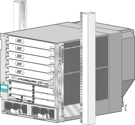
Figure 3-3 Lower and Upper Center-Mounting Brackets (with PRP-3 Installed)
Installing the Chassis in a Rack
You install the chassis in the equipment rack by setting the chassis in position against the rack rails and then securing it to the rack or optional center-mounting brackets with screws through holes in the rack-mounting flanges on either side of the chassis.
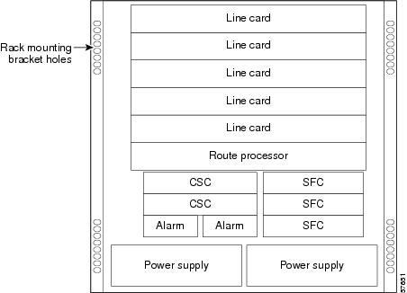
To accommodate racks with different hole patterns in their rails, the chassis rack-mounting flanges have two groups of eight oblong screw holes on either side as shown in Figure 3-4. The mounting holes in the chassis flanges are spaced so that one mounting hole in each hole group aligns with a hole in the rack rail or optional center-mounting bracket. By using the corresponding mounting hole (in the same hole group) on the opposite side of the chassis, you can level the chassis in the rack.

Warning ![]() Two or more people should install the router to minimize the risk of personal injury and damage to the equipment.
Two or more people should install the router to minimize the risk of personal injury and damage to the equipment.
Refer to Figure 3-4 and use the following procedure to install the chassis in a rack.
Step 1 ![]() Move the router as close to the installation location as possible without interfering with the installation process.
Move the router as close to the installation location as possible without interfering with the installation process.
Step 2 ![]() With one person lifting from the front and one from the rear of the chassis, lift the chassis off the pallet and position the chassis in the rack.
With one person lifting from the front and one from the rear of the chassis, lift the chassis off the pallet and position the chassis in the rack.

Note ![]() A third person might be needed to assist in lifting and positioning the chassis in the rack.
A third person might be needed to assist in lifting and positioning the chassis in the rack.
Step 3 ![]() Install the screws to secure the chassis to the rack:
Install the screws to secure the chassis to the rack:
a. ![]() Look at the bottom mounting holes on the chassis rack-mount flanges. Align one of the holes with a mounting hole in the rack.
Look at the bottom mounting holes on the chassis rack-mount flanges. Align one of the holes with a mounting hole in the rack.
b. ![]() Install one of the mounting screws provided.
Install one of the mounting screws provided.
c. ![]() On the other side of the chassis, adjust the position of the chassis so that the same mounting hole in the bottom group of mounting holes is aligned with a hole in the rack.
On the other side of the chassis, adjust the position of the chassis so that the same mounting hole in the bottom group of mounting holes is aligned with a hole in the rack.
d. ![]() Install one of the mounting screws provided.
Install one of the mounting screws provided.
Step 4 ![]() Repeat Step 3a through Step 3d for additional mounting holes.
Repeat Step 3a through Step 3d for additional mounting holes.

Step 5 ![]() Use a screwdriver to tighten all the screws.
Use a screwdriver to tighten all the screws.
Figure 3-4 Chassis Mounting Bracket Holes
Installing the Chassis on a Tabletop or Flat Surface
Use the following procedure to install the Cisco XR 12406 router on a tabletop or other stable flat surface.
Step 1 ![]() Move the router as close to the installation location as possible.
Move the router as close to the installation location as possible.

Step 2 ![]() With one person positioned at the front of the chassis and one at the rear, lift the chassis off the pallet and position the chassis on the flat surface.
With one person positioned at the front of the chassis and one at the rear, lift the chassis off the pallet and position the chassis on the flat surface.
Step 3 ![]() Secure the chassis to the flat surface to ensure that it does not fall off.
Secure the chassis to the flat surface to ensure that it does not fall off.
You can use the same mounting hardware that secured your router to the shipping pallet to secure the chassis to the flat surface.
Supplemental Bonding and Grounding Connections
Before you connect power or turn on your Cisco XR 12406 router, you must provide an adequate system ground for the router. The equipment grounding should be in accordance with local and national electrical codes.
If you are not installing the Cisco XR 12406 router in a NEBS environment, you can choose to bypass these guidelines and rely on the safety earth ground connection supplied using the 5-15 15A North American plug to the AC-powered PEMs, and the main terminal block ground connection for DC-powered PEMs.
•![]() On Cisco XR 12406 routers configured for AC-input operation, the AC PDU is equipped with a three-wire electrical grounding-type connector that accept three-wire, grounding-type AC power cords such as the power cords shipped with the router. This is a safety feature.
On Cisco XR 12406 routers configured for AC-input operation, the AC PDU is equipped with a three-wire electrical grounding-type connector that accept three-wire, grounding-type AC power cords such as the power cords shipped with the router. This is a safety feature.
•![]() On Cisco XR 12406 routers configured for DC-input operation, the DC PDU is equipped with a DC power connector block with wire-connection terminals for connecting the negative lead (top terminal), the positive lead (middle terminal), and the ground lead (bottom terminal). This is a safety feature.
On Cisco XR 12406 routers configured for DC-input operation, the DC PDU is equipped with a DC power connector block with wire-connection terminals for connecting the negative lead (top terminal), the positive lead (middle terminal), and the ground lead (bottom terminal). This is a safety feature.

Note ![]() The Cisco XR 12406 router grounding architecture conforms to the DC-I (DC-isolated) method of grounding as described in Telcordia GR-1089-CORE. A DC-I architecture means that there is no connection between the DC return terminal and the frame ground. DC return and frame ground are isolated from one another at the router.
The Cisco XR 12406 router grounding architecture conforms to the DC-I (DC-isolated) method of grounding as described in Telcordia GR-1089-CORE. A DC-I architecture means that there is no connection between the DC return terminal and the frame ground. DC return and frame ground are isolated from one another at the router.
If the router is installed in a NEBS environment, we strongly recommend that you connect the central office ground system or interior equipment grounding system to the supplemental bonding and grounding point on the router chassis. This grounding point consists of threaded inserts is located on the side of the chassis near the back of the chassis (Figure 3-5). It is also referred to as the NEBS bonding and grounding receptacle, and is intended to satisfy the Telcordia NEBS requirements for supplemental bonding and grounding connections.
Figure 3-5 Supplemental Bonding and Grounding Port for NEBS Compliance
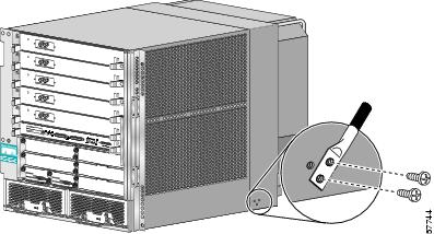
Figure 3-6 Supplemental Bonding and Grounding Port for NEBS Compliance (with PRP-3 Installed)
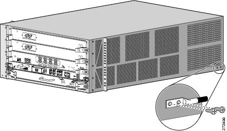
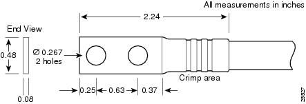
Use a dual-hole lug to connect to the chassis with two 6.3-mm (M6) screws on the 0.63-inch (16-mm) centers as shown in Figure 3-5 and Figure 3-7. The lug can be ordered from Cisco (Part Number 32-0607-01).
Figure 3-7 Cable Lug
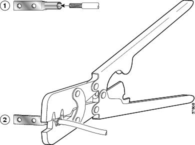
The dual-hole lug is crimped onto a grounding wire of a wire size and length determined by your router location and facility environment. The crimping tool shown in Figure 3-8 is a standard crimping tool obtainable from many sources.
Figure 3-8 Crimping the Lug
|
|
Place ground wire in the lug |
|
Crimp the lug |

Note ![]() The three threaded inserts that make up the grounding receptacle are set in a triangle so that you can choose any two of the three holes to attach the lug and grounding cable.
The three threaded inserts that make up the grounding receptacle are set in a triangle so that you can choose any two of the three holes to attach the lug and grounding cable.
Connecting RP and Line Card Cables
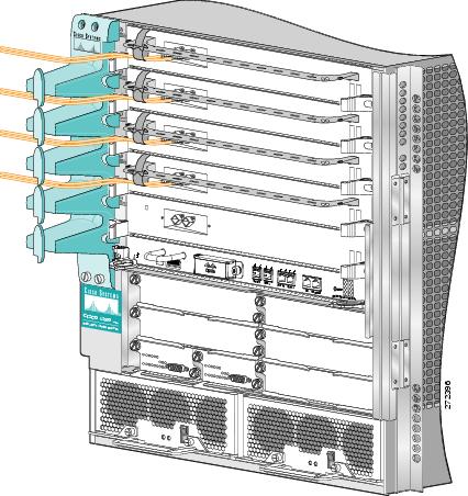
Refer to Figure 3-9 and use the following procedure to connect RP and line card cables.
Step 1 ![]() Proceeding from left to right, identify the cables that attach to the first RP or line card.
Proceeding from left to right, identify the cables that attach to the first RP or line card.
Step 2 ![]() Connect the network interface cables:
Connect the network interface cables:
a. ![]() Carefully route the identified cable through the cable-management tray and over to the card interface port; connect one cable at a time.
Carefully route the identified cable through the cable-management tray and over to the card interface port; connect one cable at a time.
b. ![]() Proceeding from left to right carefully wrap the cables using the velcro straps.
Proceeding from left to right carefully wrap the cables using the velcro straps.

Step 3 ![]() Route the cable through the fingers on the vertical chassis cable-management bracket and turn the latch on the front of the bracket to secure the cables in the bracket.
Route the cable through the fingers on the vertical chassis cable-management bracket and turn the latch on the front of the bracket to secure the cables in the bracket.
Figure 3-9 Chassis Cable-Management Bracket
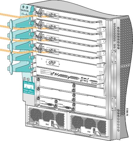
Figure 3-10 Chassis Cable-Management Bracket (with PRP-3 Installed)
Connecting Alarm Card Cables
The Cisco XR 12406 router has two alarm cards. Each alarm card is equipped with a standard DB-9 connector, labeled ALARM. This connector can be used to connect the router to an external site alarm maintenance system so that critical, major, and minor alarms generated in the router also energize alarm relays on the alarm card which activate the external site alarm. Appendix A, "Cisco XR 12406 Router Technical Specifications and Warnings," lists the pin-to-signal correspondence between the connector pins and the alarm card relay contacts.
Because alarm connector cables are entirely dependent on installation site circumstances, these cables are not available from Cisco Systems.

Note ![]() Only safety extra-low voltage (SELV) circuits can be connected to the alarm connector. Maximum rating for the alarm circuit is 2A, 50VA.
Only safety extra-low voltage (SELV) circuits can be connected to the alarm connector. Maximum rating for the alarm circuit is 2A, 50VA.
To comply with the intrabuilding lightning surge requirements of GR-1089-CORE, Issue II, Revision 01, February 1999, use a shielded cable when connecting to the external alarm port on the alarm card. The cable must consist of shielded cable terminated by shielded connectors on both ends, with the cable shield material tied to both connectors.
Connecting to the Console and Auxiliary Ports
This section provides the information for connecting console terminals and other auxiliary devices to the console and auxiliary ports on the router. Both Data Set Ready (DSR) and Data Carrier Detect (DCD) signals are active when the system is running. The console port does not support modem control or hardware flow control.
The system console port on the PRP is a DCE RJ-45 receptacle for connecting a data terminal, which you must configure. The console port is labeled Console, as shown in Figure 3-11.
Check your terminal's documentation to determine the baud rate of the terminal you plan to use. If your documentation does not specify settings use the following terminal settings:
1. ![]() Baud to 9600
Baud to 9600
2. ![]() Data bits to 8
Data bits to 8
3. ![]() Parity to no parity
Parity to no parity
4. ![]() Stop bits to 2
Stop bits to 2
The console port requires a straight-through RJ-45 cable.

Note ![]() To comply with Telcordia GR-1089 NEBS standard for electromagnetic compatibility and safety, connect all console, auxiliary, Ethernet, and BITS interfaces only to intrabuilding or non-exposed wiring or cabling. The intrabuilding cable must be shielded and the shield must be grounded at both ends.
To comply with Telcordia GR-1089 NEBS standard for electromagnetic compatibility and safety, connect all console, auxiliary, Ethernet, and BITS interfaces only to intrabuilding or non-exposed wiring or cabling. The intrabuilding cable must be shielded and the shield must be grounded at both ends.
Figure 3-11 PRP Console and Auxiliary Port Connections
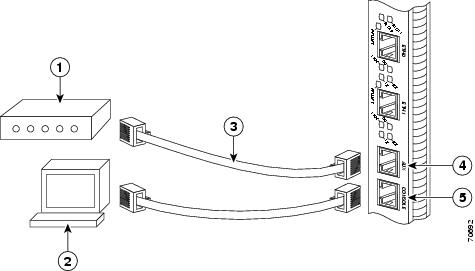
|
|
Modem |
|
Auxiliary port |
|
|
Console terminal |
|
Console port |
|
|
RJ-45 Ethernet cables |
|
— |

Note ![]() The console and auxiliary ports are both asynchronous serial ports; any devices connected to these ports must be capable of asynchronous transmission. Asynchronous is the most common type of serial device; for example, most modems are asynchronous devices.
The console and auxiliary ports are both asynchronous serial ports; any devices connected to these ports must be capable of asynchronous transmission. Asynchronous is the most common type of serial device; for example, most modems are asynchronous devices.
PRP Console Port Signals
The console port on the PRP is a DCE RJ-45 receptacle. Table 3-1 lists the signal-to-pin correspondence for the PRP console port.
|
|
|
|
|
|---|---|---|---|
11 |
— |
— |
— |
2 |
DTR |
Output |
Data Terminal Ready |
3 |
TxD |
Output |
Transmit Data |
4 |
GND |
— |
Signal Ground |
5 |
GND |
— |
Signal Ground |
6 |
RxD |
Input |
Receive Data |
7 |
DSR |
Input |
Data Set Ready |
81 |
— |
— |
— |
1 These pins are not connected. |
PRP Auxiliary Port Signals
The auxiliary port on the PRP is a DTE, RJ-45 plug for connecting a modem or other DCE device (such as a CSU/DSU or another router) to the router. The port is labeled AUX, as shown in Figure 3-11. The asynchronous auxiliary port supports hardware flow control and modem control. Table 3-2 lists the signal-to-pin correspondence for the PRP auxiliary port.
Installing a Flash Memory Card
By default, a Flash memory card (Figure 3-12) containing a valid Cisco IOS XR software image is inserted in PCMCIA slot 0 before the router is shipped. PCMCIA slot 0 (SLOT-0) is the bottom slot and slot 1 (Slot-1) is the top slot. Both Flash memory card slots on each RP can be used at the same time.
The software configuration register is set to 0x0102, which causes the router to boot automatically from the Cisco IOS XR software image stored on the Flash memory card.
Figure 3-12 Flash Memory Card Slot Opening
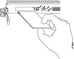
Figure 3-13 PRP-3 External CompactFlash Opening

Ensure that a console terminal is connected to the RP console port and turned on, or that you have a remote login to the router from another device through a Telnet session.
Connecting the PRP to an Ethernet Network
The PRP includes two 10/100 Mbps Ethernet ports, each using an 8-pin RJ-45 receptacle for either IEEE 802.3 10BASE-T (10 Mbps) or IEEE 802.3u 100BASE-TX (100 Mbps) connections. The transmission speed of the Ethernet ports is auto-sensing by default and is user configurable.
To connect cables to the PRP Ethernet interfaces (ports labeled ETH0 and ETH1), attach the Category 5 UTP cable directly to a RJ-45 receptacle on the PRP.

Note ![]() The Ethernet interfaces on the PRP are end-station devices, not repeaters; therefore, you must connect an Ethernet interface to a repeater or hub.
The Ethernet interfaces on the PRP are end-station devices, not repeaters; therefore, you must connect an Ethernet interface to a repeater or hub.
RJ-45 cables are not available from Cisco Systems, but are available from outside commercial cable vendors.

Note ![]() Use cables that comply with EIA/TIA-568 standards. See Table 3-4 and Table 3-5 for cable recommendations and specifications.
Use cables that comply with EIA/TIA-568 standards. See Table 3-4 and Table 3-5 for cable recommendations and specifications.

Note ![]() To comply with Telcordia GR-1089 NEBS standard for electromagnetic compatibility and safety, connect all console, auxiliary, and Ethernet interfaces only to intrabuilding or non-exposed wiring or cabling. The intrabuilding cable must be shielded and the shield must be grounded at both ends.
To comply with Telcordia GR-1089 NEBS standard for electromagnetic compatibility and safety, connect all console, auxiliary, and Ethernet interfaces only to intrabuilding or non-exposed wiring or cabling. The intrabuilding cable must be shielded and the shield must be grounded at both ends.

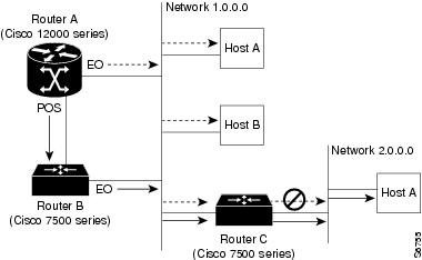
Figure 3-14 shows an example of the functionality of an Ethernet port. In this example, you cannot access Network 2.0.0.0 through the Ethernet port (ETH0) on the PRP in Router A; you can only access the hosts and Router C, which are in Network 1.0.0.0 (see dotted arrows in Figure 3-14).
To access Network 2.0.0.0 from Router A, use an interface port on one of the line cards (in this example, a Packet-over-SONET [POS] line card in Router A) to go through Router B, through Router C, and into Network 2.0.0.0. (see solid arrows in Figure 3-14).
Figure 3-14 Using the Ethernet Port on the PRP
PRP Ethernet Connections
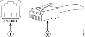
Figure 3-15 shows a PRP RJ-45 receptacle and cable connector. The RJ-45 connection does not require an external transceiver. The RJ-45 connection requires Category 5 unshielded twisted-pair (UTP) cables, which are not available from Cisco Systems, but are available from commercial cable vendors. Table 3-3 lists the signal-to-pin correspondence for the RJ-45 receptacle.
Figure 3-15 RJ-45 Receptacle and Plug (Horizontal Orientation)
|
|
RJ-45 receptacle |
|
Category 5 UTP cable with plug |

Warning ![]() The ports labeled Ethernet, 10BASE-T, Token Ring, Console, and AUX are safety extra-low voltage (SELV) circuits. SELV circuits should only be connected to other SELV circuits. Because the BRI circuits are treated like telephone network voltage, avoid connecting the SELV circuit to the telephone network voltage (TNV) circuits.
The ports labeled Ethernet, 10BASE-T, Token Ring, Console, and AUX are safety extra-low voltage (SELV) circuits. SELV circuits should only be connected to other SELV circuits. Because the BRI circuits are treated like telephone network voltage, avoid connecting the SELV circuit to the telephone network voltage (TNV) circuits.
Depending on your RJ-45 cabling requirements, use the connector pinouts shown in Figure 3-16 or Figure 3-17.
Figure 3-16 Straight-Through Cable Pinout (Connecting MDI Ethernet Port to MDI-X Wiring)
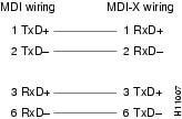
Figure 3-17 Crossover Cable Pinout for Connecting Two PRPs
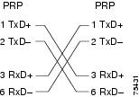
Table 3-4 lists the cabling specifications for 100-Mbps transmission over unshielded twisted-pair (UTP) cables.

Note ![]() The transmission speed of the Ethernet ports is auto-sensing by default and is user configurable.
The transmission speed of the Ethernet ports is auto-sensing by default and is user configurable.
|
|
|
|---|---|
Cable specification |
|
Cable length (max) |
— |
Segment length (max) |
328 feet (100 m) for 100BASE-TX |
Network length (max) |
656 feet (200 m)3 (with 1 repeater) |
1 EIA/TIA-568- or EIA-TIA-568 TSB-36-compliant. Not supplied by Cisco. 2 AWG = American Wire Gauge. This gauge is specified by the EIA/TIA-568 standard. 3 This length is specifically between any two stations on a repeated segment. |
Table 3-5 lists IEEE 802.3u physical characteristics for 100BASE-TX.
|
|
|
|---|---|
Data rate (Mbps) |
100 |
Signaling method |
Baseband |
Maximum segment length |
100 m between DTE1 and repeaters |
Media |
Category 5 UTP (for RJ-45) |
Topology |
Star/Hub |
1 DTE = data terminal equipment. |
Connecting to an AC Power Source
This section presents the procedure for connecting your router to an AC power source.
•![]() Original series Cisco XR 12406 routers: A power factor corrector (PFC) allows the power supply to accept AC power source voltage from an AC power source operating from 100 to 120 VAC 20-amp service in North America, and a range of from 185 to 264 VAC 16-amp service in an international environment.
Original series Cisco XR 12406 routers: A power factor corrector (PFC) allows the power supply to accept AC power source voltage from an AC power source operating from 100 to 120 VAC 20-amp service in North America, and a range of from 185 to 264 VAC 16-amp service in an international environment.
•![]() Enhanced series Cisco XR 12406 routers: Supports 220 VAC only which requires 20-amp service in North America, and 16-amp service in an international environment.
Enhanced series Cisco XR 12406 routers: Supports 220 VAC only which requires 20-amp service in North America, and 16-amp service in an international environment.

Warning ![]() The AC-input PEM power switch should be in the off position before connecting to an AC power source.
The AC-input PEM power switch should be in the off position before connecting to an AC power source.
When operating your router on a power source, the power supply bays must have one of the following power combinations installed before operating the router (Table 3-6):
|
|
|
|---|---|
AC power |
1 AC-input power supply |
2 AC-input power supplies |
|
DC power |
1 DC-input PEM |
2 DC-input PEMs |
Refer to Figure 3-18 and use the following procedure to connect AC power to the AC PDU.

Note ![]() When operating your router on a single power module, the second power module bay must have a blank filler (MAS-GSR-PWRBLANK=) installed to ensure EMI compliance.
When operating your router on a single power module, the second power module bay must have a blank filler (MAS-GSR-PWRBLANK=) installed to ensure EMI compliance.
Step 1 ![]() Attach an ESD-preventive strap to your wrist and connect the leash to the chassis or to another grounded, bare metal surface.
Attach an ESD-preventive strap to your wrist and connect the leash to the chassis or to another grounded, bare metal surface.
Step 2 ![]() Locate the two AC power cords and remove them from their shipping packaging. Verify that the AC power cords shipped with the power supplies are the correct type for your site.
Locate the two AC power cords and remove them from their shipping packaging. Verify that the AC power cords shipped with the power supplies are the correct type for your site.

Note ![]() If you have received the wrong type of AC power cord, contact your service representative for a replacement.
If you have received the wrong type of AC power cord, contact your service representative for a replacement.
Step 3 ![]() Plug the socket end of each AC power cord into a receptacle on the PDU (Figure 3-18).
Plug the socket end of each AC power cord into a receptacle on the PDU (Figure 3-18).
Figure 3-18 AC Power Distribution Unit
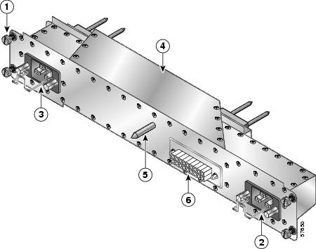
|
|
Captive screws (four) |
|
AC power distribution unit |
|
|
AC power cord receptacle A |
|
Guide pin |
|
|
AC power cord receptacle B |
|
Blower module connector |
Step 4 ![]() Insert the plug end of each AC power cord into the AC power source outlet.
Insert the plug end of each AC power cord into the AC power source outlet.
For full redundancy, connect each AC-input power supply to an independent power circuit with its own circuit breaker. We also recommend that you use an uninterruptable power source (UPS) to protect against power failures at your site.
Step 5 ![]() Verify that the AC power source circuit breaker servicing each of the AC-input power supplies is switched on.
Verify that the AC power source circuit breaker servicing each of the AC-input power supplies is switched on.
Connecting to a DC Power Source
Each DC PDU should be connected to separate DC sources using six threaded terminals. Two terminals for negative (source DC), two terminals for positive (source DC return), and two terminals for ground. The DC power cable leads should be 6 American Wiring Gauge (AWG) high strand count wire. The PEM accepts DC power source voltage from a dedicated 35-Amp service DC power source operating between -48 to -60 VDC.

Note ![]() We recommend each DC PDU be connected to an independent power source for full redundancy. We also recommend that you use an uninterruptable power source (UPS) to protect against power failures at your site.
We recommend each DC PDU be connected to an independent power source for full redundancy. We also recommend that you use an uninterruptable power source (UPS) to protect against power failures at your site.
Use the following procedure to connect the router to a DC power source.

Warning ![]() The circuit breaker switch on the faceplate of the DC-input PEM should be in the OFF position.
The circuit breaker switch on the faceplate of the DC-input PEM should be in the OFF position.
Step 1 ![]() Attach an ESD-preventive strap to your wrist and connect the leash to the chassis or to another grounded, bare metal surface.
Attach an ESD-preventive strap to your wrist and connect the leash to the chassis or to another grounded, bare metal surface.
Step 2 ![]() Locate the DC power blocks on the back of the PDU (Figure 3-19).
Locate the DC power blocks on the back of the PDU (Figure 3-19).
Figure 3-19 DC PDU
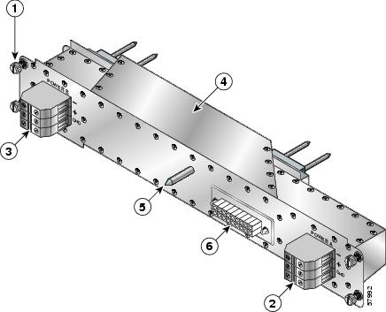
|
|
Captive screws (four) |
|
DC PDU |
|
|
DC power connector block (A) |
|
Guide pin |
|
|
DC power connector block (B) |
|
Blower module connector |
Step 3 ![]() Connect the source DC power leads to the three terminal ports in the DC power connector block in the following order (Figure 3-20):
Connect the source DC power leads to the three terminal ports in the DC power connector block in the following order (Figure 3-20):
•![]() Ground lead first (bottom port on the connector block)
Ground lead first (bottom port on the connector block)
•![]() Positive lead second (middle port on the connector block)
Positive lead second (middle port on the connector block)
•![]() Negative lead last (top port on the connector block)
Negative lead last (top port on the connector block)
a. ![]() Push the lead into the connector block port.
Push the lead into the connector block port.
b. ![]() Use a flat-blade screwdriver to tighten the set screw and secure the lead.
Use a flat-blade screwdriver to tighten the set screw and secure the lead.
c. ![]() Repeat Step 3a and Step 3b for the remaining leads and for the second PDU connector block.
Repeat Step 3a and Step 3b for the remaining leads and for the second PDU connector block.
Figure 3-20 DC PDU Power Connector Block
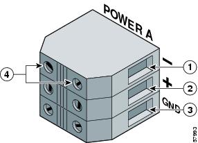
|
|
Negative terminal port |
|
Ground terminal port |
|
|
Positive terminal port |
|
Terminal port connector screws |
Step 4 ![]() Verify that the source DC circuit breaker servicing the DC PDU is switched on.
Verify that the source DC circuit breaker servicing the DC PDU is switched on.
Powering On the Router—First Time
Use the following procedure to power on the router for the first time.
Step 1 ![]() Check the following list before you power on the router:
Check the following list before you power on the router:
•![]() All cards are fully inserted in the card cage and all captive screws are tight
All cards are fully inserted in the card cage and all captive screws are tight

Caution
•![]() Line card cable-management brackets are attached to their respective line cards
Line card cable-management brackets are attached to their respective line cards
•![]() Interface cables are routed neatly through the line card cable-management bracket
Interface cables are routed neatly through the line card cable-management bracket
•![]() Interface cables are completely seated in their line card connectors
Interface cables are completely seated in their line card connectors
•![]() Interface cables are routed neatly through the chassis cable-management bracket
Interface cables are routed neatly through the chassis cable-management bracket
•![]() PEMs are fully inserted in to each AC PEM bay or DC PDU and DC PEM bay
PEMs are fully inserted in to each AC PEM bay or DC PDU and DC PEM bay
•![]() PEM cables are securely connected to the PEM
PEM cables are securely connected to the PEM
•![]() Power cables are securely connected to the PDU, the power source and are secured with appropriate strain relief.
Power cables are securely connected to the PDU, the power source and are secured with appropriate strain relief.
•![]() Empty card slots or card bays are filled with card blanks to ensure proper air flow through the chassis and electromagnetic compatibility (EMC)
Empty card slots or card bays are filled with card blanks to ensure proper air flow through the chassis and electromagnetic compatibility (EMC)
Step 2 ![]() Power on the router by switching on all the circuit breakers and/or plug the power cord into an active power source that controls power to the router's AC PEM or DC power distribution unit (PDU).
Power on the router by switching on all the circuit breakers and/or plug the power cord into an active power source that controls power to the router's AC PEM or DC power distribution unit (PDU).
Step 3 ![]() You should observe the following LED confirmation:
You should observe the following LED confirmation:
•![]() For a router equipped with AC-input power supplies:
For a router equipped with AC-input power supplies:
–![]() Green LED labeled AC—When the power module is fully seated in its bay and is receiving source power within the required range, this LED should be on. It indicates that AC power is present and is within specified limits. The power supply fan should also be on.
Green LED labeled AC—When the power module is fully seated in its bay and is receiving source power within the required range, this LED should be on. It indicates that AC power is present and is within specified limits. The power supply fan should also be on.
–![]() Green LED labeled DC—Power supply is operating normally in a powered-on condition.
Green LED labeled DC—Power supply is operating normally in a powered-on condition.
•![]() For a router equipped with DC-input PEMs:
For a router equipped with DC-input PEMs:
–![]() Green LED labeled INPUT OK—When the power module is fully seated in its bay and is receiving source power within the required range, this LED should be on. It indicates that DC power is present and is within specified limits. The power supply fan should also be on.
Green LED labeled INPUT OK—When the power module is fully seated in its bay and is receiving source power within the required range, this LED should be on. It indicates that DC power is present and is within specified limits. The power supply fan should also be on.
–![]() Green LED labeled OUTPUT OK—DC-input PEM is operating normally in a powered-on condition.
Green LED labeled OUTPUT OK—DC-input PEM is operating normally in a powered-on condition.
–![]() Amber LED labeled MISWIRE—Should be off. When it is on, it indicates that the input is wired backward at the PDU input.
Amber LED labeled MISWIRE—Should be off. When it is on, it indicates that the input is wired backward at the PDU input.
Step 4 ![]() Visually check the two LEDs on the front of the blower module at the back of the router:
Visually check the two LEDs on the front of the blower module at the back of the router:
•![]() Green LED labeled OK—Should be on
Green LED labeled OK—Should be on
•![]() Red LED labeled FAIL—Should be off
Red LED labeled FAIL—Should be off
Step 5 ![]() Listen for the blowers in the blower module; you should immediately hear them operating.
Listen for the blowers in the blower module; you should immediately hear them operating.

Note ![]() In a noisy environment, the blowers might be difficult to hear; in that case, place your hand in front of the exhaust vents at the rear of the chassis to verify that the blowers are operating.
In a noisy environment, the blowers might be difficult to hear; in that case, place your hand in front of the exhaust vents at the rear of the chassis to verify that the blowers are operating.
Step 6 ![]() Visually check the LEDs on the two alarm cards (Figure 3-21):
Visually check the LEDs on the two alarm cards (Figure 3-21):
LEDs that normally should be off:
•![]() One MBUS status LED labeled FAIL
One MBUS status LED labeled FAIL
•![]() Two CSC status LEDs labeled FAIL
Two CSC status LEDs labeled FAIL
•![]() Three SFC status LEDs labeled FAIL
Three SFC status LEDs labeled FAIL
•![]() Three router alarm LEDs labeled CRITICAL, MAJOR, MINOR
Three router alarm LEDs labeled CRITICAL, MAJOR, MINOR
LEDs that normally should be on:
•![]() One MBUS status LED labeled ENABLED
One MBUS status LED labeled ENABLED
•![]() Two CSC status LEDs labeled ENABLED
Two CSC status LEDs labeled ENABLED
•![]() Three SFC status LEDs labeled ENABLED
Three SFC status LEDs labeled ENABLED
Figure 3-21 Alarm Card LEDs On/Off Conditions
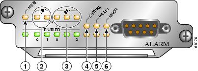
|
|
MBus status LED |
|
Critical alarm LED |
|
|
CSC status LEDs (two) |
|
Major alarm LED |
|
|
SFC status LEDs (three) |
|
Minor alarm LED |
Step 7 ![]() On the console terminal, verify that the console displays the system banner and that the system and all interfaces initialize successfully.
On the console terminal, verify that the console displays the system banner and that the system and all interfaces initialize successfully.
If the router does not power on, or if any interfaces do not initialize properly, see Chapter 4, "Troubleshooting the Installation". If you are still unable to resolve the problem, contact your Cisco service representative for assistance.
External Network Interface
After configuration, the RP and line cards can communicate with external networks.
You do not need to configure the network interfaces immediately, but you cannot connect to a network until you configure the interfaces for operation in your networking environment.

Note ![]() The interface-specific LEDs on the line cards go on when the line card interfaces are configured.
The interface-specific LEDs on the line cards go on when the line card interfaces are configured.
To verify correct operation of each line card interface, complete the first-time setup procedures and configuration, then check the status of the interfaces against the LED descriptions in the configuration notes for each line card.
If the system does not complete each of the boot process steps, go to Chapter 4, "Troubleshooting the Installation".
Manually Booting the System
If your router does not find a valid system configuration image, or if you interrupt the boot sequence, the system might enter read-only memory (ROM) monitor mode and display the ROM monitor prompt (rommon>). From ROM monitor mode, you have access to a number of commands to locate and boot a valid system image.
Boot Process Overview
The example below assumes that the router is plugged into a power source and the router is running, blower module fans are audible, and alarm card ENABLED LEDs are lit up.
The following is an example of a typical boot process:
•![]() The RP MBus module receives the correct DC voltage and starts executing MBus software.
The RP MBus module receives the correct DC voltage and starts executing MBus software.
•![]() The RP determines the router configuration by sending a message through the alarm card requesting all installed devices to identify themselves. Their responses provide slot numbers and card and component types. The RP, line cards, CSCs, and SFCs are then powered up.
The RP determines the router configuration by sending a message through the alarm card requesting all installed devices to identify themselves. Their responses provide slot numbers and card and component types. The RP, line cards, CSCs, and SFCs are then powered up.
•![]() The power-on-reset logic of the RP is delayed long enough to allow power and both local and CSC clocks to stabilize.
The power-on-reset logic of the RP is delayed long enough to allow power and both local and CSC clocks to stabilize.
•![]() After the power-on reset logic is released, the RP begins to execute the ROM monitor software.
After the power-on reset logic is released, the RP begins to execute the ROM monitor software.
•![]() If the ROM monitor is configured to autoboot, it automatically loads and boots the Cisco IOS XR software.
If the ROM monitor is configured to autoboot, it automatically loads and boots the Cisco IOS XR software.
•![]() If the ROM monitor is not configured to autoboot, boot the Cisco IOS XR software manually. See the "Manually Booting the System" section.
If the ROM monitor is not configured to autoboot, boot the Cisco IOS XR software manually. See the "Manually Booting the System" section.
•![]() When the Cisco IOS XR software boots, it polls all other cards in the system, powers them up, and loads the Cisco IOS XR software they require.
When the Cisco IOS XR software boots, it polls all other cards in the system, powers them up, and loads the Cisco IOS XR software they require.
Starting the Router and Observing Initial Conditions
Observe the following conditions the first time you start your router:
•![]() Power cables to the PDU are fully connected to both the PDU and the power source, and are secured with appropriate strain relief.
Power cables to the PDU are fully connected to both the PDU and the power source, and are secured with appropriate strain relief.
•![]() Empty card slots or card bays are filled with card blanks. This ensures proper air flow through the chassis and electromagnetic compatibility (EMC).
Empty card slots or card bays are filled with card blanks. This ensures proper air flow through the chassis and electromagnetic compatibility (EMC).
•![]() All cards are fully inserted in their cages and bays.
All cards are fully inserted in their cages and bays.
•![]() All captive screws are tightened.
All captive screws are tightened.
•![]() Line card cable-management brackets are attached to their respective line cards.
Line card cable-management brackets are attached to their respective line cards.
•![]() Interface cables are completely seated in their line card connectors.
Interface cables are completely seated in their line card connectors.
•![]() Interface cables are routed neatly through the chassis cable-management bracket.
Interface cables are routed neatly through the chassis cable-management bracket.

•![]() Power modules are fully inserted in their bays and the ejector levers are completely closed and secured.
Power modules are fully inserted in their bays and the ejector levers are completely closed and secured.
•![]() Check the power module LEDs:
Check the power module LEDs:
For a router equipped with AC-input power supplies, when a power supply is seated in its bay and is receiving the required power source:
–![]() The green LED labeled AC should be on. It indicates that AC power source is present and is within specified limits.
The green LED labeled AC should be on. It indicates that AC power source is present and is within specified limits.
–![]() The green LED labeled DC should be on. It indicates that the power supply is operating normally in a powered-on condition.
The green LED labeled DC should be on. It indicates that the power supply is operating normally in a powered-on condition.
For a router equipped with DC-input PEMs—When a PEM is seated in its bay and is receiving the required power source:
–![]() The green LED labeled INPUT OK should be on. It indicates that DC power source is present and is within specified limits.
The green LED labeled INPUT OK should be on. It indicates that DC power source is present and is within specified limits.
–![]() The green LED labeled OUTPUT OK should be on. It indicates that the PEM is operating normally in a powered-on condition.
The green LED labeled OUTPUT OK should be on. It indicates that the PEM is operating normally in a powered-on condition.
–![]() The amber LED labeled MISWIRE should be off. When it is on, it indicates that the input is wired backward at the PDU input.
The amber LED labeled MISWIRE should be off. When it is on, it indicates that the input is wired backward at the PDU input.
•![]() Each power module fan should also be on.
Each power module fan should also be on.
At the rear of the chassis, observe the status of the two LEDs on the blower module. When the blower module is operating correctly, the left LED should should be on (green) and the right LED (red) should be off.
Listen for the blowers in the blower module; they should be running. In a noisy environment, the blower might be difficult to hear. In that case, place your hand near the exhaust vents at the top and bottom rear of the chassis to verify that the blower is operating.
RP Alphanumeric LED
RP alphanumeric LEDs are located at one end of the RP faceplate, near the ejector lever. Figure 3-22 shows the RP LED displays.
Figure 3-22 RP Alphanumeric LED Displays
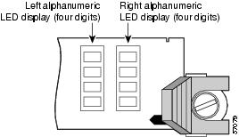
Each 4-digit display shows part of a 2-line system message. During the RP boot process, the LED displays present a sequence of messages similar to that shown in Table 3-7.
|
|
|
|
|---|---|---|
MROM |
The MBus microcode begins to execute; nnnn is the microcode version number. For example, microcode version 1.17 displays as 0117.1 Note |
MBus controller |
LMEM |
Low memory on the RP is being tested. |
RP ROM monitor |
MEM |
The size of main memory on the RP is being discovered. |
RP ROM monitor |
RP |
The system is operational and ready to execute basic Cisco IOS XR software commands at the ROM monitor prompt ( |
RP ROM monitor |
RP |
A valid Cisco IOS XR image is running. |
RP IOS XR software |
PRI |
The RP is enabled and recognized as the system primary. A valid Cisco IOS XR image is running. |
RP IOS XR software |
SEC |
The RP is enabled and recognized as the system secondary. A valid Cisco IOS XR image is running. |
RP IOS XR software |
1 The version of MBus microcode running on your system might be different. |
RP Interfaces Using the RP LEDs
The Cisco XR 12000 Series Router uses the performance route processor (PRP-2).

Note ![]() When not explicitly specified, this publication uses the term route processor (RP) to indicate the PRP.
When not explicitly specified, this publication uses the term route processor (RP) to indicate the PRP.
The RJ-45 port LEDs on the RP indicate the following conditions:
•![]() System and RP status
System and RP status
•![]() Which Flash memory card slot is active
Which Flash memory card slot is active
•![]() Which Ethernet connection is in use
Which Ethernet connection is in use
•![]() What is occurring on the Ethernet interface
What is occurring on the Ethernet interface
The alphanumeric LED displays indicate a successful RP boot.
PRP Interfaces Using the PRP LEDs
The PRP faceplate has eight device or port LED activity indicators (Figure 3-23). Each LED goes on when its corresponding PCMCIA slot is accessed. The ports are:
•![]() Two PCMCIA slot activity LEDs labeled SLOT-0 and SLOT-1.
Two PCMCIA slot activity LEDs labeled SLOT-0 and SLOT-1.
•![]() Four RJ-45 Ethernet port activity LEDs. These LEDs are used by the RJ-45 Ethernet connectors. Each connector includes four LEDs that indicate link activity (LINK), port enabled (EN), data transmission (TX), and data reception (RX).
Four RJ-45 Ethernet port activity LEDs. These LEDs are used by the RJ-45 Ethernet connectors. Each connector includes four LEDs that indicate link activity (LINK), port enabled (EN), data transmission (TX), and data reception (RX).
•![]() Two Ethernet port-selection LEDs labeled PRIMARY. These two LEDs, when on, identify which of the two Ethernet connections is selected. Because both ports are supported on the PRP, the LED on port ETH0 is always on. The ETH1 LED goes on when it is selected.
Two Ethernet port-selection LEDs labeled PRIMARY. These two LEDs, when on, identify which of the two Ethernet connections is selected. Because both ports are supported on the PRP, the LED on port ETH0 is always on. The ETH1 LED goes on when it is selected.
Figure 3-23 PRP LEDs

LINK |
Indicates link activity |
|---|---|
EN |
Indicates the port is enabled |
TX |
Indicates data transmission |
RX |
Indicates data reception |
Figure 3-24 PRP-3 LEDs

Manually Booting the System
If your router does not find a valid system configuration image, or if you interrupt the boot sequence, the system might enter read-only memory (ROM) monitor mode and display the ROM monitor prompt (rommon>). From ROM monitor mode, you have access to a number of commands to locate and boot a valid system image.
 Feedback