
Raw Socket Transport on SD-Routing Devices, Release 17.18.x
What’s new and changed
This table lists the features available with the current release.
|
Cisco IOS XE release |
Feature Name |
Description |
Supported platforms |
|---|---|---|---|
|
Cisco IOS XE 17.18.1a |
Raw Socket Transport on SD-Routing devices |
This feature introduces support to configure Raw Socket transport on SD-Routing devices using Feature Parcels in Cisco SD-WAN Manager. |
|
Raw Socket transport for SD-Routing devices
Raw Socket transports serial data through an IP network. This feature helps in transportation of Supervisory Control and Data Acquisition (SCADA) data from Remote Terminal Units (RTUs) and serves as an alternative to the Block Serial Tunnel (BSTUN) protocol.
Raw Socket transport uses either TCP or UDP as the transport protocol. You can configure an interface to use one protocol at a time, but not both simultaneously. TCP transport suits control applications that require acknowledged and sequenced data delivery. For latency-sensitive applications, such as line SEL relays, UDP transport delivers serial data faster than TCP.
In Cisco IOS XE Release 17.18.1a, you can configure Raw Socket transport using Feature Parcels in Cisco Catalyst SD-WAN Manager without configuring and managing multiple commands.
Benefits of Raw Socket transport
- Ease of configuration :The Feature Parcel support in Cisco Catalyst SD-WAN Manager offers a pre-packaged template where you can input configurations easily and provision the changes to multiple devices. This removes the overhead of configuring using multiple commands and provisioning changes per device.
- Traffic segmentation : By default, the Raw Socket data is routed using the details in the global routing table without any segmentation or isolation of network traffic. But for added security, you can configure Raw Socket data to be routed through a Service VRF by using the routing table dedicated for the VRF. This provides a way to manage and control network traffic for different services, ensuring that each service has its own isolated network path.
Limitations of Raw Socket transport
Configuring a loopback interface on a Raw Socket interace is only supported on Cisco Catalyst IR8340 Rugged Series Router. A loopback interface cannot be configured on a Raw Socket interface that is used in Cisco Catalyst IR1101 Rugged Series Router and Cisco Catalyst IR1800 Rugged Series Router.
Devices for which Raw Socket transport can be configured
Determine the topology and encapsulation for Raw Socket transport
Raw Socket transport can be configured in a client-server model or a peer-to-peer topology depending on how you want data to be delivered. The data delivery is determined by how packets are encapsulated. Raw Socket transport can use either TCP or UDP as the transport protocol.
You can configure an interface to use one protocol at a time, but not both simultaneously. TCP transport suits control applications that require acknowledged and sequenced data delivery and uses a client-server model. For latency-sensitive applications, such as line SEL relays, UDP transport delivers serial data faster than TCP transport and uses a peer-to-peer model.
TCP Encapsulation
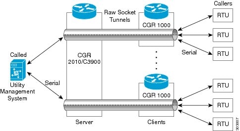
TCP encapsulation for Raw Socket transport uses a client-server model. At most one server and multiple clients can be configured on a single asynchronous serial line. In a client mode, the Industrial Router can initiate up to 32 TCP sessions to raw socket servers, which can be other Industrial Routers or third-party devices. This figure shows a sample Raw Socket using TCP encapsulation.
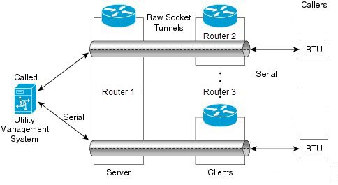
In this example, serial data is transferred between RTUs and a utility management system across an IP network that includes several Industrial Routers. One Industrial Router (Router 1) acts as a raw socket server, listening for TCP connection requests from the other Industrial Router (Router 2 and Router 3), which are configured as raw socket clients.
A raw socket client receives streams of serial data from the Remote Terminal Units (RTUs) and accumulates this data in its buffer, then places the data into packets, based on user-specified packetization criteria. The Raw Socket client initiates a TCP connection with the Raw Socket server and sends the packetized data across the IP network to the Raw Socket server, which retrieves the serial data from the packets and sends it to the serial interface, and on to the utility management system.
 Note
NoteWhen you configure the router's serial link interface as a server, the client router's serial link interface acts as its peer, and vice versa.
UDP Encapsulation
UDP transport uses a peer-to-peer model. Multiple UDP connections can be configured on an asynchronous serial line.
In this example, serial data is transferred between RTUs (Remote Terminal Unit) and a utility management system across an IP network that includes two routers (Router 1 which is an IR1800 and Router 2 which is an IR1101) that are configured as Raw Socket UDP peers.
In this example, the Raw Socket UDP peer receives streams of serial data from the RTUs and accumulates this data in its buffer, then places the data into packets, based on user-specified packetization criteria. The Raw Socket UDP peer sends the packetized data across the IP network to the raw socket peer at the other end, which retrieves the serial data from the packets and sends it to the serial interface, and on to the utility management system.
Determine how the traffic from the Raw Socket should be routed
By default, the Raw Socket data is routed using the details in the global routing table without any segmentation or isolation of network traffic. But for added security, you can configure Raw Socket data to be routed through a Service VRF by using the routing table dedicated for the VRF.
This provides a way to manage and control network traffic for different services, ensuring that each service has its own isolated network path.
Determine how serial data is packetized
Packetization in networking is the process of dividing data into small, manageable units called packets, which are then transmitted over a network. This involves encapsulating the data with a header that contains control information like source and destination addresses. At the receiving end, these packets are reassembled to reconstruct the original data.
During Raw Socket configuration specify a character that triggers the device to packetize the data in its buffer and forward it to the Raw Socket peer. For example, to indicate end of transmission, a special character, such as carriage return (CR, ASCII 13) or line feed (LF, ASCII 10), can be used.
Configure Raw Socket transport using Transport and Management Profile
By default, the Raw Socket data is routed using the details in the global routing table without any segmentation or isolation of network traffic.
Step 1 | On the Cisco Catalyst SD-WAN Manager, select . Select the solution type as SD Routing. | ||||||||||||||||
Step 2 | Select a configuration group from the list that is displayed. Create a new Transport and Management profile or select an existing profile. Select the profile, click Edit. | ||||||||||||||||
Step 3 | Select Global VRF. Click Add New to configure the Global VRF. Specify a name to identify the Global VRF. Optionally, add a description for the Global VRF. | ||||||||||||||||
Step 4 | Click the + icon and select Raw Socket. Click Add New to configure Raw Socket transport. Specify a name to identify the Raw Socket interface. Optionally, add a description for the Raw Socket. Specify these details:
| ||||||||||||||||
Step 5 | Click Save. |
What to do next
For added security, you can configure Raw Socket data to be routed through a Service VRF by using the dedicated routing table for the VRF. See, Configure Raw Socket transport using Service profile.
Configure Raw Socket transport using Service profile
For added security, you can configure Raw Socket data to be routed through a Service VRF by using the dedicated routing table for the VRF.
Step 1 | On the Cisco Catalyst SD-WAN Manager, select . Select Solution as SD Routing. |
Step 2 | Create a new Service Profile or edit an existing one. Click +Add New Feature, select VRF. For details on values for each field, see Configure a VRF in Service Profile . |
Step 3 | Click +, select Raw Socket. Refer Step 4 of Configure Raw Socket transport using Transport and Management Profile for details. |
Step 4 | Click Save. |
Associate and deploy the Configuration Group to an SD-Routing device
Before you begin
Step 1 | On Cisco SD-WAN Manager, select the Configuration Group created earlier. |
Step 2 | Click + Add and select the devices from the list. Click Save to attach the configuration group to the selected devices. |
Step 3 | To provision the configuration changes, click Deploy.
|
Monitor Raw Socket on SD-Routing devices using Cisco Catalyst SD-WAN Manager
This section provides details on how to monitor Raw Socket transport using Cisco Catalyst SD-WAN Manager.
Monitor Raw Socket using Monitor dashboard
This section provides details on how to monitor Raw Socket transport using Monitor dashboard in Cisco Catalyst SD-WAN Manager.
Step 1 | On the Cisco Catalyst SD-WAN Manager, select . Select a device from the list. |
Step 2 | Select Real Time. From Device Options, select one among the session details:
|
Monitor Raw Socket using commands
Use these commands to monitor Raw Socket sessions information. These commands can be executed using terminal in Cisco Catalyst SD-WAN Manager:
- show raw-socket udp sessions
- show raw-socket udp detail
- show raw-socket udp statistics
- show raw-socket tcp sessions
- show raw-socket tcp detail
- show raw-socket tcp statistics
- show raw-socket udp sessions local
- show raw-socket tcp sessions local