Multicast Configuration Guide for the Cisco NCS 6000 Series Router, Release 5.0.x
Bias-Free Language
The documentation set for this product strives to use bias-free language. For the purposes of this documentation set, bias-free is defined as language that does not imply discrimination based on age, disability, gender, racial identity, ethnic identity, sexual orientation, socioeconomic status, and intersectionality. Exceptions may be present in the documentation due to language that is hardcoded in the user interfaces of the product software, language used based on RFP documentation, or language that is used by a referenced third-party product. Learn more about how Cisco is using Inclusive Language.
- Updated:
- November 28, 2013
Chapter: Implementing Multicast Routing on Cisco IOS XR Software
- Prerequisites for Implementing Multicast Routing
- Information About Implementing Multicast Routing
- Key Protocols and Features Supported in the Cisco IOS XR Software Multicast Routing Implementation
- Multicast Routing Functional Overview
- PIM-SM, PIM-SSM, and PIM-BIDIR
- Internet Group Management Protocol
- Protocol Independent Multicast
- PIM Shared Tree and Source Tree (Shortest Path Tree)
- Multicast-Intact
- Designated Routers
- Rendezvous Points
- Auto-RP
- PIM Bootstrap Router
- Reverse-Path Forwarding
- Multitopology Routing
- Label Switched Multicast (LSM) Multicast Label Distribution Protocol (mLDP) based Multicast VPN (mVPN) Support
- Multicast Source Discovery Protocol
- Multicast Nonstop Forwarding
- Multicast Configuration Submodes
- Understanding Interface Configuration Inheritance
- Understanding Interface Configuration Inheritance Disablement
- Understanding Enabling and Disabling Interfaces
- Multicast Routing Information Base
- Multicast Forwarding Information Base
- MSDP MD5 Password Authentication
- Configuring Route Policy for Static RPF
- Configuration Examples for Implementing Multicast Routing on Software
- Additional References
Implementing
Multicast Routing on Cisco IOS XR Software
Multicast routing is a bandwidth-conserving technology that reduces traffic by simultaneously delivering a single stream of information to potentially thousands of corporate recipients and homes. Applications that take advantage of multicast routing include video conferencing, corporate communications, distance learning, and distribution of software, stock quotes, and news.
This document assumes that you are familiar with IPv4 multicast routing configuration tasks and concepts for Cisco IOS XR Software .
Multicast routing allows a host to send packets to a subset of all hosts as a group transmission rather than to a single host, as in unicast transmission, or to all hosts, as in broadcast transmission. The subset of hosts is known as group members and are identified by a single multicast group address that falls under the IP Class D address range from 224.0.0.0 through 239.255.255.255.
Feature History for Configuring Multicast Routing on the Cisco NCS 6000 Series Routers
|
Release |
Modification |
|---|---|
|
Release 5.0.0 |
This feature was introduced. |
|
Release 6.1.2 |
Point-to-Multipoint Traffic Engineering with GTM feature was introduced. |
|
Release 6.1.2 |
MLDP Edge feature was introduced. |
- Prerequisites for Implementing Multicast Routing
- Information About Implementing Multicast Routing
- Configuring Route Policy for Static RPF
- Configuration Examples for Implementing Multicast Routing on Software
- Additional References
Prerequisites for Implementing Multicast Routing
-
You must install and activate the multicast package.
-
You must be in a user group associated with a task group that includes the proper task IDs. The command reference guides include the task IDs required for each command. If you suspect user group assignment is preventing you from using a command, contact your AAA administrator for assistance.
-
You must be familiar with IPv4 multicast routing configuration tasks and concepts.
-
Unicast routing must be operational.
Information About Implementing Multicast Routing
- Key Protocols and Features Supported in the Cisco IOS XR Software Multicast Routing Implementation
- Multicast Routing Functional Overview
- PIM-SM, PIM-SSM, and PIM-BIDIR
- Internet Group Management Protocol
- Protocol Independent Multicast
- PIM Shared Tree and Source Tree (Shortest Path Tree)
- Multicast-Intact
- Designated Routers
- Rendezvous Points
- Auto-RP
- PIM Bootstrap Router
- Reverse-Path Forwarding
- Multitopology Routing
- Label Switched Multicast (LSM) Multicast Label Distribution Protocol (mLDP) based Multicast VPN (mVPN) Support
- Multicast Source Discovery Protocol
- Multicast Nonstop Forwarding
- Multicast Configuration Submodes
- Understanding Interface Configuration Inheritance
- Understanding Interface Configuration Inheritance Disablement
- Understanding Enabling and Disabling Interfaces
- Multicast Routing Information Base
- Multicast Forwarding Information Base
- MSDP MD5 Password Authentication
Key Protocols and Features Supported in the Cisco IOS XR Software Multicast Routing Implementation
Multicast Routing Functional Overview
Traditional IP communication allows a host to send packets to a single host (unicast transmission) or to all hosts (broadcast transmission). Multicast provides a third scheme, allowing a host to send a single data stream to a subset of all hosts (group transmission) at about the same time. IP hosts are known as group members.
Packets delivered to group members are identified by a single multicast group address. Multicast packets are delivered to a group using best-effort reliability, just like IP unicast packets.
The multicast environment consists of senders and receivers. Any host, regardless of whether it is a member of a group, can send to a group. However, only the members of a group receive the message.
A multicast address is chosen for the receivers in a multicast group. Senders use that group address as the destination address of a datagram to reach all members of the group.
Membership in a multicast group is dynamic; hosts can join and leave at any time. There is no restriction on the location or number of members in a multicast group. A host can be a member of more than one multicast group at a time.
How active a multicast group is and what members it has can vary from group to group and from time to time. A multicast group can be active for a long time, or it may be very short-lived. Membership in a group can change constantly. A group that has members may have no activity.
Many multimedia applications involve multiple participants. Multicast is naturally suitable for this communication paradigm.
Multicast Routing Implementation
Cisco IOS XR Software supports the following protocols to implement multicast routing:
-
IGMP used between hosts on a LAN and the routers on that LAN to track the multicast groups of which hosts are members.
-
Protocol Independent Multicast in sparse mode (PIM-SM) is used between routers so that they can track which multicast packets to forward to each other and to their directly connected LANs.
-
Protocol Independent Multicast in Source-Specific Multicast (PIM-SSM) is similar to PIM-SM with the additional ability to report interest in receiving packets from specific source addresses (or from all but the specific source addresses), to an IP multicast address.
-
PIM Bidirectional is a variant of the Protocol Independent Multicast suit of routing protocols for IP multicast. PIM-BIDIR is designed to be used for many-to-many applications within individual PIM domains.
This image shows IGMP and PIM-SM operating in a multicast environment.
PIM-SM, PIM-SSM, and PIM-BIDIR
Protocl Independent Multicast (PIM) is a multicast routing protocol used to create multicast distribution trees, which are used to forward multicast data packets. PIM is an efficient IP routing protocol that is “independent” of a routing table, unlike other multicast protocols such as Multicast Open Shortest Path First (MOSPF) or Distance Vector Multicast Routing Protocol (DVMRP).
Cisco IOS XR Software supports Protocol Independent Multicast in sparse mode (PIM-SM), Protocol Independent Multicast in Source-Specific Multicast (PIM-SSM), and Protocol Independent Multicast in Bi-directional mode (BIDIR) permitting these modes to operate on your router at the same time.
PIM-SM and PIM-SSM supports one-to-many applications by greatly simplifying the protocol mechanics for deployment ease. Bidir PIM helps deploy emerging communication and financial applications that rely on a many-to-many applications model. BIDIR PIM enables these applications by allowing them to easily scale to a very large number of groups and sources by eliminating the maintenance of source state.
PIM-SM Operations
PIM in sparse mode operation is used in a multicast network when relatively few routers are involved in each multicast and these routers do not forward multicast packets for a group, unless there is an explicit request for the traffic.
For more information about PIM-SM, see the PIM-Sparse Mode.
PIM-SSM Operations
PIM in Source-Specific Multicast operation uses information found on source addresses for a multicast group provided by receivers and performs source filtering on traffic.
-
By default, PIM-SSM operates in the 232.0.0.0/8 multicast group range for IPv4 . To configure these values, use the ssm range command.
-
If SSM is deployed in a network already configured for PIM-SM, only the last-hop routers must be upgraded with Cisco IOS XR Software that supports the SSM feature.
-
No MSDP SA messages within the SSM range are accepted, generated, or forwarded.
Restrictions for PIM-SM and PIM-SSM, and PIM BIDIR
Interoperability with SSM
PIM-SM operations within the SSM range of addresses change to PIM-SSM. In this mode, only PIM (S,G) join and prune messages are generated by the router, and no (S,G) RP shared tree or (*,G) shared tree messages are generated.
IGMP Version
To report multicast memberships to neighboring multicast routers, hosts use IGMP, and all routers on the subnet must be configured with the same version of IGMP.
A router running Cisco IOS XR Software does not automatically detect Version 1 systems. You must use the version command in router IGMP configuration submode to configure the IGMP version.
Internet Group Management Protocol
Cisco IOS XR Software provides support for Internet Group Management Protocol (IGMP) over IPv4
IGMP a means for hosts to indicate which multicast traffic they are interested in and for routers to control and limit the flow of multicast traffic throughout the network. Routers build state by means of IGMP messages; that is, router queries and host reports.
A set of queries and hosts that receive multicast data streams from the same source is called a multicast group. Hosts use IGMP messages to join and leave multicast groups.
 Note | IGMP messages use group addresses, which are Class D IP addresses. The high-order four bits of a Class D address are 1110. Host group addresses can be in the range 224.0.0.0 to 239.255.255.255. The address 224.0.0.0 is guaranteed not to be assigned to any group. The address 224.0.0.1 is assigned to all systems on a subnet. The address 224.0.0.2 is assigned to all routers on a subnet. |
IGMP Versions
The following points describe IGMP versions 1, 2, and 3:
-
IGMP Version 1 provides for the basic query-response mechanism that allows the multicast router to determine which multicast groups are active and for other processes that enable hosts to join and leave a multicast group.
-
IGMP Version 2 extends IGMP allowing such features as the IGMP query timeout and the maximum query-response time. See RFC 2236.
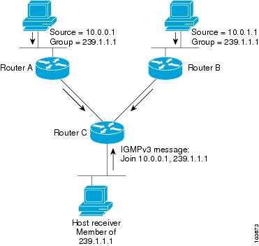
IGMP Routing Example
Figure 1 illustrates two sources, 10.0.0.1 and 10.0.1.1, that are multicasting to group 239.1.1.1. The receiver wants to receive traffic addressed to group 239.1.1.1 from source 10.0.0.1 but not from source 10.0.1.1. The host must send an IGMPv3 message containing a list of sources and groups (S, G) that it wants to join and a list of sources and groups (S, G) that it wants to leave. Router C can now use this information to prune traffic from Source 10.0.1.1 so that only Source 10.0.0.1 traffic is being delivered to
Router C.
Note | When configuring IGMP, ensure that all systems on the subnet support the same IGMP version. The router does not automatically detect Version 1 systems. Configure the router for Version 2 if your hosts do not support Version 3. |
Protocol Independent Multicast
Protocol Independent Multicast (PIM) is a routing protocol designed to send and receive multicast routing updates. Proper operation of multicast depends on knowing the unicast paths towards a source or an RP. PIM relies on unicast routing protocols to derive this reverse-path forwarding (RPF) information. As the name PIM implies, it functions independently of the unicast protocols being used. PIM relies on the Routing Information Base (RIB) for RPF information.
The Cisco IOS XR implementation of PIM is based on RFC 4601 Protocol Independent Multicast - Sparse Mode (PIM-SM): Protocol Specification. For more information, see RFC 4601 and the Protocol Independent Multicast (PIM): Motivation and Architecture Internet Engineering Task Force (IETF) Internet draft.
Note | Cisco IOS XR Software supports PIM-SM, PIM-SSM, and PIM Version 2 only. PIM Version 1 hello messages that arrive from neighbors are rejected. |
PIM-Sparse Mode
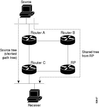
Typically, PIM in sparse mode (PIM-SM) operation is used in a multicast network when relatively few routers are involved in each multicast. Routers do not forward multicast packets for a group, unless there is an explicit request for traffic. Requests are accomplished using PIM join messages, which are sent hop by hop toward the root node of the tree. The root node of a tree in PIM-SM is the rendezvous point (RP) in the case of a shared tree or the first-hop router that is directly connected to the multicast source in the case of a shortest path tree (SPT). The RP keeps track of multicast groups, and the sources that send multicast packets are registered with the RP by the first-hop router of the source.
As a PIM join travels up the tree, routers along the path set up the multicast forwarding state so that the requested multicast traffic is forwarded back down the tree. When multicast traffic is no longer needed, a router sends a PIM prune message up the tree toward the root node to prune (or remove) the unnecessary traffic. As this PIM prune travels hop by hop up the tree, each router updates its forwarding state appropriately. Ultimately, the forwarding state associated with a multicast group or source is removed. Additionally, if prunes are not explicitly sent, the PIM state will timeout and be removed in the absence of any further join messages.
PIM-SM is the best choice for multicast networks that have potential members at the end of WAN links.
PIM-Source Specific Multicast
In many multicast deployments where the source is known, protocol-independent multicast-source-specific multicast (PIM-SSM) mapping is the obvious multicast routing protocol choice to use because of its simplicity. Typical multicast deployments that benefit from PIM-SSM consist of entertainment-type solutions like the ETTH space, or financial deployments that completely rely on static forwarding.
PIM-SSM is derived from PIM-SM. However, whereas PIM-SM allows for the data transmission of all sources sending to a particular group in response to PIM join messages, the SSM feature forwards traffic to receivers only from those sources that the receivers have explicitly joined. Because PIM joins and prunes are sent directly towards the source sending traffic, an RP and shared trees are unnecessary and are disallowed. SSM is used to optimize bandwidth utilization and deny unwanted Internet broadcast traffic. The source is provided by interested receivers through IGMPv3 membership reports.
In SSM, delivery of datagrams is based on (S,G) channels. Traffic for one (S,G) channel consists of datagrams with an IP unicast source address S and the multicast group address G as the IP destination address. Systems receive traffic by becoming members of the (S,G) channel. Signaling is not required, but receivers must subscribe or unsubscribe to (S,G) channels to receive or not receive traffic from specific sources. Channel subscription signaling uses IGMP to include mode membership reports, which are supported only in Version 3 of IGMP (IGMPv3).
To run SSM with IGMPv3, SSM must be supported on the multicast router, the host where the application is running, and the application itself. Cisco IOS XR Software allows SSM configuration for an arbitrary subset of the IP multicast address range 224.0.0.0 through 239.255.255.255. When an SSM range is defined, existing IP multicast receiver applications do not receive any traffic when they try to use addresses in the SSM range, unless the application is modified to use explicit (S,G) channel subscription.
PIM Shared Tree and Source Tree (Shortest Path Tree)
In PIM-SM, the rendezvous point (RP) is used to bridge sources sending data to a particular group with receivers sending joins for that group. In the initial setup of state, interested receivers receive data from senders to the group across a single data distribution tree rooted at the RP. This type of distribution tree is called a shared tree or rendezvous point tree (RPT) as illustrated in Figure 1 . Data from senders is delivered to the RP for distribution to group members joined to the shared tree.
Unless the spt-threshold infinity command is configured, this initial state gives way as soon as traffic is received on the leaf routers (designated router closest to the host receivers). When the leaf router receives traffic from the RP on the RPT, the router initiates a switch to a data distribution tree rooted at the source sending traffic. This type of distribution tree is called a shortest path tree or source tree. By default, the Cisco IOS XR Software switches to a source tree when it receives the first data packet from a source.
The following process describes the move from shared tree to source tree in more detail:
-
Receiver joins a group; leaf Router C sends a join message toward RP.
-
RP puts link to Router C in its outgoing interface list.
-
Source sends data; Router A encapsulates data in Register and sends it to RP.
-
RP forwards data down the shared tree to Router C and sends a join message toward Source. At this point, data may arrive twice at the RP, once encapsulated and once natively.
-
When data arrives natively (unencapsulated) at RP, RP sends a register-stop message to Router A.
-
By default, receipt of the first data packet prompts Router C to send a join message toward Source.
-
When Router C receives data on (S,G), it sends a prune message for Source up the shared tree.
-
RP deletes the link to Router C from outgoing interface of (S,G). RP triggers a prune message toward Source.
Join and prune messages are sent for sources and RPs. They are sent hop by hop and are processed by each PIM router along the path to the source or RP. Register and register-stop messages are not sent hop by hop. They are exchanged using direct unicast communication between the designated router that is directly connected to a source and the RP for the group.
 Tip | The spt-threshold infinity command lets you configure the router so that it never switches to the shortest path tree (SPT). |
Multicast-Intact
The multicast-intact feature provides the ability to run multicast routing (PIM) when Interior Gateway Protocol (IGP) shortcuts are configured and active on the router. Both Open Shortest Path First, version 2 (OSPFv2), and Intermediate System-to-Intermediate System (IS-IS) support the multicast-intact feature. Multiprotocol Label Switching Traffic Engineering (MPLS-TE) and IP multicast coexistence is supported in Cisco IOS XR Software by using the mpls traffic-eng multicast-intact IS-IS or OSPF router command. See Routing Configuration Guide for Cisco NCS 6000 Series Routers for information on configuring multicast intact using IS-IS and OSPF commands.
You can enable multicast-intact in the IGP when multicast routing protocols (PIM) are configured and IGP shortcuts are configured on the router. IGP shortcuts are MPLS tunnels that are exposed to IGP. The IGPs route the IP traffic over these tunnels to destinations that are downstream from the egress router of the tunnel (from an SPF perspective). PIM cannot use IGP shortcuts for propagating PIM joins because reverse path forwarding (RPF) cannot work across a unidirectional tunnel.
When you enable multicast-intact on an IGP, the IGP publishes a parallel or alternate set of equal-cost next-hops for use by PIM. These next-hops are called mcast-intact next-hops. The mcast-intact next-hops have the following attributes:
-
They are guaranteed not to contain any IGP shortcuts.
-
They are not used for unicast routing but are used only by PIM to look up an IPv4 next hop to a PIM source.
-
They are not published to the Forwarding Information Base (FIB).
-
When multicast-intact is enabled on an IGP, all IPv4 destinations that were learned through link-state advertisements are published with a set equal-cost mcast-intact next-hops to the RIB. This attribute applies even when the native next-hops have no IGP shortcuts.
-
In IS-IS, the max-paths limit is applied by counting both the native and mcast-intact next-hops together. (In OSPFv2, the behavior is slightly different.)
Designated Routers
Cisco routers use PIM-SM to forward multicast traffic and follow an election process to select a designated router (DR) when there is more than one router on a LAN segment.
The designated router is responsible for sending PIM register and PIM join and prune messages toward the RP to inform it about host group membership.
If there are multiple PIM-SM routers on a LAN, a designated router must be elected to avoid duplicating multicast traffic for connected hosts. The PIM router with the highest IP address becomes the DR for the LAN unless you choose to force the DR election by use of the dr-priority command. The DR priority option allows you to specify the DR priority of each router on the LAN segment (default priority = 1) so that the router with the highest priority is elected as the DR. If all routers on the LAN segment have the same priority, the highest IP address is again used as the tiebreaker.
Figure 1 illustrates what happens on a multiaccess segment. Router A (10.0.0.253) and Router B (10.0.0.251) are connected to a common multiaccess Ethernet segment with Host A (10.0.0.1) as an active receiver for Group A. As the Explicit Join model is used, only Router A, operating as the DR, sends joins to the RP to construct the shared tree for Group A. If Router B were also permitted to send (*, G) joins to the RP, parallel paths would be created and Host A would receive duplicate multicast traffic. When Host A begins to source multicast traffic to the group, the DR’s responsibility is to send register messages to the RP. Again, if both routers were assigned the responsibility, the RP would receive duplicate multicast packets.
If the DR fails, the PIM-SM provides a way to detect the failure of Router A and to elect a failover DR. If the DR (Router A) were to become inoperable, Router B would detect this situation when its neighbor adjacency with Router A timed out. Because Router B has been hearing IGMP membership reports from Host A, it already has IGMP state for Group A on this interface and immediately sends a join to the RP when it becomes the new DR. This step reestablishes traffic flow down a new branch of the shared tree using Router B. Additionally, if Host A were sourcing traffic, Router B would initiate a new register process immediately after receiving the next multicast packet from Host A. This action would trigger the RP to join the SPT to Host A, using a new branch through Router B.
Tip | Two PIM routers are neighbors if there is a direct connection between them. To display your PIM neighbors, use the show pim neighbor command in EXEC mode. |
Note | DR election process is required only on multiaccess LANs. The last-hop router directly connected to the host is the DR. |
Rendezvous Points
When PIM is configured in sparse mode, you must choose one or more routers to operate as a rendezvous point (RP). A rendezvous point is a single common root placed at a chosen point of a shared distribution tree, as illustrated in Figure 1. A rendezvous point can be either configured statically in each box or learned through a dynamic mechanism.
PIM DRs forward data from directly connected multicast sources to the rendezvous point for distribution down the shared tree. Data is forwarded to the rendezvous point in one of two ways:
-
Encapsulated in register packets and unicast directly to the rendezvous point by the first-hop router operating as the DR
-
Multicast forwarded by the RPF forwarding algorithm, described in the Reverse-Path Forwarding, if the rendezvous point has itself joined the source tree.
The rendezvous point address is used by first-hop routers to send PIM register messages on behalf of a host sending a packet to the group. The rendezvous point address is also used by last-hop routers to send PIM join and prune messages to the rendezvous point to inform it about group membership. You must configure the rendezvous point address on all routers (including the rendezvous point router).
A PIM router can be a rendezvous point for more than one group. Only one rendezvous point address can be used at a time within a PIM domain. The conditions specified by the access list determine for which groups the router is a rendezvous point.
You can either manually configure a PIM router to function as a rendezvous point or allow the rendezvous point to learn group-to-RP mappings automatically by configuring Auto-RP or BSR. (For more information, see the Auto-RP section that follows and PIM Bootstrap Router.)
Auto-RP
Automatic route processing (Auto-RP) is a feature that automates the distribution of group-to-RP mappings in a PIM network. This feature has these benefits:
-
It is easy to use multiple RPs within a network to serve different group ranges.
-
It allows load splitting among different RPs.
-
It facilitates the arrangement of RPs according to the location of group participants.
-
It avoids inconsistent, manual RP configurations that might cause connectivity problems.
Multiple RPs can be used to serve different group ranges or to serve as hot backups for each other. To ensure that Auto-RP functions, configure routers as candidate RPs so that they can announce their interest in operating as an RP for certain group ranges. Additionally, a router must be designated as an RP-mapping agent that receives the RP-announcement messages from the candidate RPs, and arbitrates conflicts. The RP-mapping agent sends the consistent group-to-RP mappings to all remaining routers. Thus, all routers automatically determine which RP to use for the groups they support.
Tip | By default, if a given group address is covered by group-to-RP mappings from both static RP configuration, and is discovered using Auto-RP or PIM BSR, the Auto-RP or PIM BSR range is preferred. To override the default, and use only the RP mapping, use the rp-address override keyword. |
Note | If you configure PIM in sparse mode and do not configure Auto-RP, you must statically configure an RP as described in the Configuring a Static RP and Allowing Backward Compatibility. When router interfaces are configured in sparse mode, Auto-RP can still be used if all routers are configured with a static RP address for the Auto-RP groups. |
PIM Bootstrap Router
The PIM bootstrap router (BSR) provides a fault-tolerant, automated RP discovery and distribution mechanism that simplifies the Auto-RP process. This feature is enabled by default allowing routers to dynamically learn the group-to-RP mappings.
PIM uses the BSR to discover and announce RP-set information for each group prefix to all the routers in a PIM domain. This is the same function accomplished by Auto-RP, but the BSR is part of the PIM Version 2 specification. The BSR mechanism interoperates with Auto-RP on Cisco routers.
To avoid a single point of failure, you can configure several candidate BSRs in a PIM domain. A BSR is elected among the candidate BSRs automatically. Candidates use bootstrap messages to discover which BSR has the highest priority. The candidate with the highest priority sends an announcement to all PIM routers in the PIM domain that it is the BSR.
Routers that are configured as candidate RPs unicast to the BSR the group range for which they are responsible. The BSR includes this information in its bootstrap messages and disseminates it to all PIM routers in the domain. Based on this information, all routers are able to map multicast groups to specific RPs. As long as a router is receiving the bootstrap message, it has a current RP map.
Reverse-Path Forwarding
Reverse-path forwarding (RPF) is an algorithm used for forwarding multicast datagrams. It functions as follows:
-
If a router receives a datagram on an interface it uses to send unicast packets to the source, the packet has arrived on the RPF interface.
-
If the packet arrives on the RPF interface, a router forwards the packet out the interfaces present in the outgoing interface list of a multicast routing table entry.
-
If the packet does not arrive on the RPF interface, the packet is silently discarded to prevent loops.
PIM uses both source trees and RP-rooted shared trees to forward datagrams; the RPF check is performed differently for each, as follows:
-
If a PIM router has an (S,G) entry present in the multicast routing table (a source-tree state), the router performs the RPF check against the IP address of the source for the multicast packet.
-
If a PIM router has no explicit source-tree state, this is considered a shared-tree state. The router performs the RPF check on the address of the RP, which is known when members join the group.
Sparse-mode PIM uses the RPF lookup function to determine where it needs to send joins and prunes. (S,G) joins (which are source-tree states) are sent toward the source. (*,G) joins (which are shared-tree states) are sent toward the RP.
Multitopology Routing
Multitopology routing allows you to manipulate network traffic flow when desirable (for example, to broadcast duplicate video streams) to flow over non-overlapping paths.
PIM uses a routing policy that supports matching on source or group address to select the topology in which to look up the reverse-path forwarding (RPF) path to the source. If you do not configure a policy, the existing behavior (to select a default table) remains in force.
Currently, IS-IS and PIM routing protocols alone support multitopology-enabled network.
Label Switched Multicast (LSM) Multicast Label Distribution Protocol (mLDP) based Multicast VPN (mVPN) Support
Label Switch Multicast (LSM) is MPLS technology extensions to support multicast using label encapsulation. Next-generation MVPN is based on Multicast Label Distribution Protocol (mLDP), which can be used to build P2MP and MP2MP LSPs through a MPLS network. These LSPs can be used for transporting both IPv4 and IPv6 multicast packets, either in the global table or VPN context.
- Benefits of LSM MLDP based MVPN
- Configuring MLDP MVPN
- P2MP and MP2MP Label Switched Paths
- Packet Flow in mLDP-based Multicast VPN
- Realizing a mLDP-based Multicast VPN
- Characteristics of mLDP Profiles
- Summary of Supported MVPN Profiles
Benefits of LSM MLDP based MVPN
LSM provides these benefits when compared to GRE core tunnels that are currently used to transport customer traffic in the core:
Configuring MLDP MVPN
The MLDP MVPN configuration enables IPv4 multicast packet delivery using MPLS. This configuration uses MPLS labels to construct default and data Multicast Distribution Trees (MDTs). The MPLS replication is used as a forwarding mechanism in the core network. For MLDP MVPN configuration to work, ensure that the global MPLS MLDP configuration is enabled. To configure MVPN extranet support, configure the source multicast VPN Routing and Forwarding (mVRF) on the receiver Provider Edge (PE) router or configure the receiver mVRF on the source PE. MLDP MVPN is supported for both intranet and extranet.
P2MP and MP2MP Label Switched Paths
mLDP is an application that sets up Multipoint Label Switched Paths (MP LSPs) in MPLS networks without requiring multicast routing protocols in the MPLS core. mLDP constructs the P2MP or MP2MP LSPs without interacting with or relying upon any other multicast tree construction protocol. Using LDP extensions for MP LSPs and Unicast IP routing, mLDP can setup MP LSPs. The two types of MP LSPs that can be setup are Point-to-Multipoint (P2MP) and Multipoint-to-Multipoint (MP2MP) type LSPs.
A P2MP LSP allows traffic from a single root (ingress node) to be delivered to a number of leaves (egress nodes), where each P2MP tree is uniquely identified with a 2-tuple (root node address, P2MP LSP identifier). A P2MP LSP consists of a single root node, zero or more transit nodes, and one or more leaf nodes, where typically root and leaf nodes are PEs and transit nodes are P routers. A P2MP LSP setup is receiver-driven and is signaled using mLDP P2MP FEC, where LSP identifier is represented by the MP Opaque Value element. MP Opaque Value carries information that is known to ingress LSRs and Leaf LSRs, but need not be interpreted by transit LSRs. There can be several MP LSPs rooted at a given ingress node, each with its own identifier.
A MP2MP LSP allows traffic from multiple ingress nodes to be delivered to multiple egress nodes, where a MP2MP tree is uniquely identified with a 2-tuple (root node address, MP2MP LSP identifier). For a MP2MP LSP, all egress nodes, except the sending node, receive a packet sent from an ingress node.
A MP2MP LSP is similar to a P2MP LSP, but each leaf node acts as both an ingress and egress node. To build an MP2MP LSP, you can setup a downstream path and an upstream path so that:
Packet Flow in mLDP-based Multicast VPN
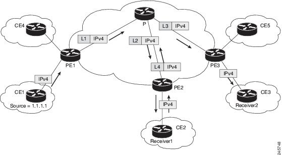
For each packet coming in, MPLS creates multiple out-labels. Packets from the source network are replicated along the path to the receiver network. The CE1 router sends out the native IP multicast traffic. The PE1 router imposes a label on the incoming multicast packet and replicates the labeled packet towards the MPLS core network. When the packet reaches the core router (P), the packet is replicated with the appropriate labels for the MP2MP default MDT or the P2MP data MDT and transported to all the egress PEs. Once the packet reaches the egress PE, the label is removed and the IP multicast packet is replicated onto the VRF interface.
Realizing a mLDP-based Multicast VPN
There are different ways a Label Switched Path (LSP) built by mLDP can be used depending on the requirement and nature of application such as:
P2MP LSPs for global table transit Multicast using in-band signaling.
P2MP/MP2MP LSPs for MVPN based on MI-PMSI or Multidirectional Inclusive Provider Multicast Service Instance (Rosen Draft).
P2MP/MP2MP LSPs for MVPN based on MS-PMSI or Multidirectional Selective Provider Multicast Service Instance (Partitioned E-LAN).
The Cisco NCS 6000 Series Router performs the following important functions for the implementation of MLDP:
Characteristics of mLDP Profiles
The characteristics of various mLDP profiles are listed in this section.
Profile 4: MS-PMSI-mLDP-MP2MP with BGP-AD
These are the characteristics of this profile:
-
MP2MP mLDP trees are used in the core.
-
The multicast traffic can be SM or SSM.
-
Extranet, Hub and Spoke, CsC, Customer-RP-discovery (Embedded-RP, AutoRP, and BSR) are supported.
-
Inter-AS Options A, B, and C are supported. VRF-Route-Import EC is announced in VPN-IP routes.
-
Each PE sends Hellos only on the trees rooted on that PE. With this, in deployment scenarios, where the number of source PEs are much lesser than the total number of PEs in the MVPN, results in a huge reduction of PIM neighbors.
Configuration rules for profiles
Rules for mLDP profiles (profile- 4)
MLDP inband signaling
MLDP Inband signaling allows the core to create (S,G) or (*,G) state without using out-of-band signaling such as BGP or PIM. It is supported in VRF (and in the global context). Both IPv4 and IPv6 multicast groups are supported.
In MLDP Inband signaling, one can configure an ACL range of multicast (S,G). This (S,G) can be transported in MLDP LSP. Each multicast channel (S,G), is 1 to 1 mapped to each tree in the inband tree. The (S,G) join, through IGMP/MLD/PIM, will be registered in MRIB, which is the client of MLDP.
MLDP In-band signalling supports transiting PIM (S,G) or (*,G) trees across a MPLS core without the need for an out-of-band protocol. In-band signaling is only supported for shared-tree-only forwarding (also known as sparse-mode threshold infinity). PIM Sparse-mode behavior is not supported (switching from (*,G) to (S,G).
The details of the MLDP profiles are discussed in the Multicast Configuration Guide for Cisco NCS 6000 Series Routers
Summary of Supported MVPN Profiles
This tables summarizes the supported MVPN profiles:
| Profile Number | Name | Opaque-value | BGP-AD | Data-MDT |
|---|---|---|---|---|
| 4 | MS- PMSI (Partition) MLDP MP2MP with BGP -AD |
Type 1 - Source- PE:Global -ID |
BGP-AD |
Multicast Source Discovery Protocol
Multicast Source Discovery Protocol (MSDP) is a mechanism to connect multiple PIM sparse-mode domains. MSDP allows multicast sources for a group to be known to all rendezvous points (RPs) in different domains. Each PIM-SM domain uses its own RPs and need not depend on RPs in other domains.
An RP in a PIM-SM domain has MSDP peering relationships with MSDP-enabled routers in other domains. Each peering relationship occurs over a TCP connection, which is maintained by the underlying routing system.
MSDP speakers exchange messages called Source Active (SA) messages. When an RP learns about a local active source, typically through a PIM register message, the MSDP process encapsulates the register in an SA message and forwards the information to its peers. The message contains the source and group information for the multicast flow, as well as any encapsulated data. If a neighboring RP has local joiners for the multicast group, the RP installs the S, G route, forwards the encapsulated data contained in the SA message, and sends PIM joins back towards the source. This process describes how a multicast path can be built between domains.
Note | Although you should configure BGP or Multiprotocol BGP for optimal MSDP interdomain operation, this is not considered necessary in the Cisco IOS XR Software implementation. For information about how BGP or Multiprotocol BGP may be used with MSDP, see the MSDP RPF rules listed in the Multicast Source Discovery Protocol (MSDP), Internet Engineering Task Force (IETF) Internet draft. |
Multicast Nonstop Forwarding
The Cisco IOS XR Software nonstop forwarding (NSF) feature for multicast enhances high availability (HA) of multicast packet forwarding. NSF prevents hardware or software failures on the control plane from disrupting the forwarding of existing packet flows through the router.
The contents of the Multicast Forwarding Information Base (MFIB) are frozen during a control plane failure. Subsequently, PIM attempts to recover normal protocol processing and state before the neighboring routers time out the PIM hello neighbor adjacency for the problematic router. This behavior prevents the NSF-capable router from being transferred to neighbors that will otherwise detect the failure through the timed-out adjacency. Routes in MFIB are marked as stale after entering NSF, and traffic continues to be forwarded (based on those routes) until NSF completion. On completion, MRIB notifies MFIB and MFIB performs a mark-and-sweep to synchronize MFIB with the current MRIB route information.
Multicast Configuration Submodes
Cisco IOS XR Software moves control plane CLI configurations to protocol-specific submodes to provide mechanisms for enabling, disabling, and configuring multicast features on a large number of interfaces.
Cisco IOS XR Software allows you to issue most commands available under submodes as one single command string from the global or XR config mode.
For example, the ssm command could be executed from the multicast-routing configuration submode like this:
RP/0/RP0/CPU0:router(config)# multicast-routing
RP/0/RP0/CPU0:router(config-mcast-ipv4)# ssm range
Alternatively, you could issue the same command from the global or XR config mode like this:
RP/0/RP0/CPU0:router(config)# multicast-routing ssm range
The following multicast protocol-specific submodes are available through these configuration submodes:
- Multicast-Routing Configuration Submode
- PIM Configuration Submode
- IGMP Configuration Submode
- MSDP Configuration Submode
Multicast-Routing Configuration Submode
When you issue the multicast-routing ipv4 command, all default multicast components (PIM, IGMP, , MFWD, and MRIB) are automatically started, and the CLI prompt changes to “config-mcast-ipv4” indicating that you have entered multicast-routing configuration submode.
PIM Configuration Submode
When you issue the router pim command, the CLI prompt changes to “config-pim-ipv4,” indicating that you have entered the default pim address-family configuration submode.
IGMP Configuration Submode
When you issue the router igmp command, the CLI prompt changes to “config-igmp,” indicating that you have entered IGMP configuration submode.
MSDP Configuration Submode
When you issue the router msdp command, the CLI prompt changes to “config-msdp,” indicating that you have entered router MSDP configuration submode.
Understanding Interface Configuration Inheritance
Cisco IOS XR Software allows you to configure commands for a large number of interfaces by applying command configuration within a multicast routing submode that could be inherited by all interfaces. To override the inheritance mechanism, you can enter interface configuration submode and explicitly enter a different command parameter.
For example, in the following configuration you could quickly specify (under router PIM configuration mode) that all existing and new PIM interfaces on your router will use the hello interval parameter of 420 seconds. However, Packet-over-SONET/SDH (POS) interface 0/1/0/1 overrides the global interface configuration and uses the hello interval time of 210 seconds.
RP/0/RP0/CPU0:router(config)# router pim
RP/0/RP0/CPU0:router(config-pim-default-ipv4)# hello-interval 420
RP/0/RP0/CPU0:router(config-pim-default-ipv4)# interface pos 0/1/0/1
RP/0/RP0/CPU0:router(config-pim-ipv4-if)# hello-interval 210
Understanding Interface Configuration Inheritance Disablement
As stated elsewhere, Cisco IOS XR Software allows you to configure multiple interfaces by applying configurations within a multicast routing submode that can be inherited by all interfaces.
To override the inheritance feature on specific interfaces or on all interfaces, you can enter the address-family IPv4 submode of multicast routing configuration mode, and enter the interface-inheritance disable command together with the interface type interface-path-id or interface all command. This causes PIM or IGMP protocols to disallow multicast routing and to allow only multicast forwarding on those interfaces specified. However, routing can still be explicitly enabled on specified individual interfaces.
For related information, see Understanding Enabling and Disabling Interfaces
Understanding Enabling and Disabling Interfaces
When the Cisco IOS XR Software multicast routing feature is configured on your router, by default, no interfaces are enabled.
To enable multicast routing and protocols on a single interface or multiple interfaces, you must explicitly enable interfaces using the interface command in multicast routing configuration mode.
To set up multicast routing on all interfaces, enter the interface all command in multicast routing configuration mode. For any interface to be fully enabled for multicast routing, it must be enabled specifically (or be default) in multicast routing configuration mode, and it must not be disabled in the PIM and IGMP configuration modes.
For example, in the following configuration, all interfaces are explicitly configured from multicast routing configuration submode:
RP/0/RP0/CPU0:router(config)# multicast-routing
RP/0/RP0/CPU0:router(config-mcast)# interface all enable
To disable an interface that was globally configured from the multicast routing configuration submode, enter interface configuration submode, as illustrated in the following example:
RP/0/RP0/CPU0:router(config-mcast)# interface GigabitEthernet0pos 0/1/0/0
RP/0/RP0/CPU0:router(config-mcast-default-ipv4-if)# disable
Multicast Routing Information Base
The Multicast Routing Information Base (MRIB) is a protocol-independent multicast routing table that describes a logical network in which one or more multicast routing protocols are running. The tables contain generic multicast routes installed by individual multicast routing protocols. There is an MRIB for every logical network in which the router is configured. MRIBs do not redistribute routes among multicast routing protocols; they select the preferred multicast route from comparable ones, and they notify their clients of changes in selected attributes of any multicast route.
Multicast Forwarding Information Base
Multicast Forwarding Information Base (MFIB) is a protocol-independent multicast forwarding system that contains unique multicast forwarding entries for each source or group pair known in a given network. There is a separate MFIB for every logical network in which the router is configured. Each MFIB entry resolves a given source or group pair to an incoming interface (IIF) for reverse forwarding (RPF) checking and an outgoing interface list (olist) for multicast forwarding.
MSDP MD5 Password Authentication
MSDP MD5 password authentication is an enhancement to support Message Digest 5 (MD5) signature protection on a TCP connection between two Multicast Source Discovery Protocol (MSDP) peers. This feature provides added security by protecting MSDP against the threat of spoofed TCP segments being introduced into the TCP connection stream.
MSDP MD5 password authentication verifies each segment sent on the TCP connection between MSDP peers. The password clear command is used to enable MD5 authentication for TCP connections between two MSDP peers. When MD5 authentication is enabled between two MSDP peers, each segment sent on the TCP connection between the peers is verified.
Note | MSDP MD5 authentication must be configured with the same password on both MSDP peers to enable the connection between them. The 'password encrypted' command is used only for applying the stored running configuration. Once you configure the MSDP MD5 authentication, you can restore the configuration using this command. |
MSDP MD5 password authentication uses an industry-standard MD5 algorithm for improved reliability and security.
Configuring Route Policy for Static RPF
1.
configure
2.
router static
3.
address-family[ipv4 |
][ multicast
|unicast]destination prefix
interface-typeinterface-path-id
4.
exit
5.
route-policypolicy-name
6.
set
rpf-topology
policy-nameaddress-family[ipv4 |]multicast
|
unicasttopologyname
7.
end
route-policy
8.
router
pim
address-family[ipv4 |]
9.
rpf topology
route-policypolicy-namepim policy
DETAILED STEPS
Configuration Examples for Implementing Multicast Routing on Software
This section provides the following configuration examples:
- Preventing Auto-RP Messages from Being Forwarded on Software: Example
- Inheritance in MSDP on Software: Example
- Configuring Route Policy for Static RPF: Example
Preventing Auto-RP Messages from Being Forwarded on Software: Example
This example shows that Auto-RP messages are prevented from being sent out of the interface 0/3/0/0. It also shows that access list 111 is used by the Auto-RP candidate and access list 222 is used by the boundary command to contain traffic on interface 0/3/0/0.
ipv4 access-list 111
 10 permit 224.1.0.0 0.0.255.255 any
 20 permit 224.2.0.0 0.0.255.255 any
!
!Access list 111 is used by the Auto-RP candidate.
!
ipv4 access-list 222
 10 deny any host 224.0.1.39
 20 deny any host 224.0.1.40
!
!Access list 222 is used by the boundary command to contain traffic (on /3/0/0) that is sent to groups 224.0.1.39 and 224.0.1.40.
!
router pim
 auto-rp mapping-agent loopback 2 scope 32 interval 30
 auto-rp candidate-rp loopback 2 scope 15 group-list 111 interval 30
multicast-routing
 interface /3/0/0
 boundary 222
!
Inheritance in MSDP on Software: Example
The following MSDP commands can be inherited by all MSDP peers when configured under router MSDP configuration mode. In addition, commands can be configured under the peer configuration mode for specific peers to override the inheritance feature.
If a command is configured in both the router msdp and peer configuration modes, the peer configuration takes precedence.
In the following example, MSDP on Router A filters Source-Active (SA) announcements on all peer groups in the address range 226/8 (except IP address 172.16.0.2); and filters SAs sourced by the originator RP 172.16.0.3 to 172.16.0.2.
MSDP peers (172.16.0.1, 172.16.0.2, and 172.17.0.1) use the loopback 0 address of Router A to set up peering. However, peer 192.168.12.2 uses the IPv4 address configured on the interface to peer with Router A.
Router A
!
ipv4 access-list 111
 10 deny ip host 172.16.0.3 any
 20 permit any any
!

ipv4 access-list 112
 10 deny any 226.0.0.0 0.255.255.255
 30 permit any any
!
router msdp
 connect-source loopback 0
 sa-filter in rp-list 111
 sa-filter out rp-list 111
 peer 172.16.0.1
!
peer 172.16.0.2
 sa-filter out list 112
!
peer 172.17.0.1
!
peer 192.168.12.2
 connect-source /2/0/0
!
Configuring Route Policy for Static RPF: Example
router static
 address-family ipv4 multicast
  202.93.192.74 /32 202.40.148.11

!
route-policy pim-policy
 set rpf-topology ipv4 multicast topology default

end-policy
!
router pim
 address-family ipv4
  rpf topology route-policy pim-policy
Additional References
Related Documents
|
Related Topic |
Document Title |
|---|---|
|
Multicast command reference document |
Multicast Command Reference for Cisco NCS 6000 Series Routers |
|
Getting started material |
|
|
Modular quality of service command reference document |
|
|
Routing command reference and configuration documents |
Routing Command Reference for Cisco NCS 6000 Series Routers Routing Configuration Guide for Cisco NCS 6000 Series Routers |
|
Information about user groups and task IDs |
System Security Configuration Guide for Cisco NCS 6000 Series Routers |
 Feedback